1
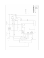
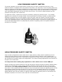
Owners Manual
Please read this manual
thoroughly before attempting to
install, connect or operate your
Watermaker.
INDEX
3.
4.
5.
6.
7.
8.
9.
10.
11.
12.
13.
14.
15.
17.
18.
19.
21.
23.
24.
27.
28.
29.
30.
32.
34.
35.
WATERMAKER PRINCIPLES
WORKING PARTS & FUNCTION
MEMBRANE PIPING DIAGRAM
PANEL LAYOUT DIAGRAM
OPERATION INSTRUCTIONS
THEORETICAL MEMBRANE PRODUCTION GRAPH
THE IMPORTANCE OF USING DECHLORINATED WATER
FLUSHING THE SYSTEM WITH FRESH WATER
SHORT PERIOD LAY-UP INSTRUCTIONS
PRESERVATIVE CHEMICAL INFORMATION
WINTER LAY-UP INSTRUCTIONS
ROUTINE MAINTENANCE
MEMBRANE CLEANING INSTRUCTIONS
CLEANING CHEMICAL #1 INFORMATION
CLEANING CHEMICAL #2 INFORMATION
INSTALLATION GUIDE
COMMISIONING
REPAIR & SERVICE INFORMATION
TROUBLESHOOTING
CONTROL BOX ELECTRICAL SCHEMATIC
REMOTE CONTROL ELECTRICAL SCHEMATIC
LOW PRESSURE SAFETY SWITCH
HIGH PRESSURE PUMP MAINTENANCE
LOW PRESSURE PUMP MAINTENANCE
SPARES PRICE LIST
WARRANTY
2
Aquafresh Reverse Osmosis Watermaker
Installation, Commissioning & Operation Manual
All Models
Owners and operators of Aquafresh water makers are urged to read this manual thoroughly as, by
understanding the principles of osmosis, operational problems will not occur and satisfaction with
your unit will be obtained.
All elements of the system are described in detail to give you a working knowledge of their function
in order that minor defects may be overcome before they lead to major problems and expensive
repairs or worse.
Please read this manual through before attempting to install, connect or
run the system.
Principles
Dictionary definitions:
Osmosis n. 1. the tendency of the solvent of a less concentrated solution of dissolved molecules to
pass through a semipermiable membrane into a more concentrated solution until both solutions are
of the same concentration.
Osmotic pressure n. the pressure necessary to prevent osmosis into a given solution when the
solution is separated from the pure solvent by a semipermiable membrane.
When the pressure on a concentrated solution of dissolved solids is increased then reverse
osmosis takes place and molecules of the pure solvent (water in our case) pass through the
membrane from the concentrated solution. The pressure required to achieve this phenomena is
proportional to the concentration of dissolved solids. ie a 1% solution of salt requires approximately
100 psi (7 Bar) and sea water at 35,000 ppm requires approximately 800 psi (55 Bar).
It is this principle that is used in the operation of your Aquafresh reverse osmosis watermaker.
3
Working Parts and Function
There are basically two types of Aquafresh watermaker. One uses an A.C. supply to drive the high
pressure pump, the other uses an engine driven high pressure pump. The model numbers are
suffixed with either AC or ED to identify each type. In the case of the engine driven units either 12
or 24 volts is required to operate the installation.
System Function
Sea Water
Sea water is drawn into the system by the low pressure, centrifugal priming pump (LP Pump), via a
3/4 inch inlet sea cock, strainer and 'L' port valve. The other position on the 'L' port valve is a 1/2
inch 'SERVICE' connection for the intake of cleaning and disinfecting solutions, this connection may
also be used to prime the LP Pump when necessary. The output of the LP Pump feeds the first (25
micron) of two system filters.
A double filter system is then added where the condition of the filters may be seen through the
transparent filter bowls or by reference to the optional low pressure gauge. In service, the filters
will darken from their natural white colour, becoming almost black when badly contaminated and in
need of changing.
From the second (5 micron) filter the sea water is fed at low pressure, of at least 3 psi, to the inlet
manifold of a positive displacement, high pressure pump. This can create a pressure of up to 1400
psi, however, the pressure is controlled to below 1000 psi by a pressure relief safety valve and
excess sea water is discharged overboard via the salt water discharge port.
The pressurised flow of sea water passes through the Reverse Osmosis Membranes (RO
membranes), the number in the system being dependant upon system size, and is then discharged
via the Pressure Regulating Valve and salt water discharge port. It is essential for a flow of salt
water, proportional to its salinity, to pass over the membranes at the correct rate and pressure. The
pressure regulating valve controls back pressure which can be adjusted up to 900 psi, depending on
salinity and water temperature, and indicated on the high pressure gauge. The sea water is then
discharged overboard via the salt water discharge port.
Fresh Water
The fresh water connections on the end of the RO membranes are interconnected and pass via the
salinity sensor to a solenoid operated 3 way valve, except in the case of the 'Simplex' unit where the
water has to be manually tasted before diversion to the vessels tanks. Water which has been
'sensed' as satisfactory causes the solenoid to operate allowing the water tanks to be filled.
Unsatisfactory water is discharged via the salt water discharge port.
Sensing of the water is achieved by measuring the conductivity of the RO membranes output. Pure
water offering lower conductivity than salt water.
The salinity control allows the user to control output in relation to local sea water salinity and
temperature. Typically in Atlantic waters the control is set lower, about level 2 whereas in the Med,
where the water salinity can be much higher, a level of 4 or more may be set.
4
5
6
Operation
Switching ON
1.
Ensure that the electrical power lamp on the Remote Control panel is illuminated.
2.
Ensure that ALL system sea cocks are fully open. Set the salinity control to the desired
position (typically 2 to 4 in UK waters).
Note: If the unit is being operated for the first time, or has been laid up with
preserving chemicals, ensure that the “salinity” control is rotated fully anticlockwise, passed the click stop, to ensure discharge of product water overboard.
Then run the system for a minimum period of 1 hour before adjusting the “salinity”
control to allow water to be stored.
3.
Depress the On/Off switch.
The LP pump will run up first followed, after a short delay, by the HP pump. If a low pressure
gauge is fitted, check that at least 7 psi is being developed, otherwise a change of filters or
fouled inlet strainer is indicated.
4.
Adjust the pressure regulating valve to give up to 825 psi, depending on water temperature
and optimum RO membrane output. Output from RO membranes can vary by as much as +
or -15% and figures are rated at a temperature of 25 Celsius. Over pressurising the RO
membranes can cause irreversible damage. In areas where salinity is low ensure that the
unit does not over produce as indicated on the product flowmeter. The maximum rate of
fresh water flow indicated on the flow meter should NOT exceed 15% of that recommended
in the 'Theoretical Membrane Production Graph'.
5.
On Simplex units water quality is assessed by the operator tasting the output before allowing
it to enter the vessels tanks and it is important that the water divert valve is closed to the
tank. Allow the unit to run for at least 5 minutes before tasting and accepting water for input
into the vessels tanks. It is recommended that the water be tasted at least every two hours
during running to ensure that water is of an acceptable quality.
On units with automatic water sensing fresh water is flowing to the storage tanks when the
green, 'FRESH' indicator is illuminated. Water is being rejected and discharged when the
yellow, 'SALT' indicator is on.
Switching OFF
1.
Adjust the pressure regulating valve to reduce the high pressure to zero psi
2.
Depress the On/Off switch ensuring that all but the power supply lamp extinguish.
On Simplex units ensure that the water divert valve is closed to the vessels tanks so that on
start-up water is dumped until an acceptable taste is sampled by the operator.
3.
To prevent inadvertent operation isolate the water making system at the main supply panel.
Note: Because a watermaker can be installed on any vessel of any age, with any
number of electrical supplies, the safest advice is always given in this manual.
However, on a modern vessel with more than adequate electrical specification and
generator sizing, there is no need to adjust the pressure valve whilst starting and
stopping the unit. The reason for winding the pressure back is to allow for very
small or older design generators to be able to cope with the starting loads of a unit
under pressure.
7
8
The Importance of Using De-Chlorinated Water
Freshwater containing chlorine will damage your watermaker
membranes.
When flushing or preserving your system, always use fresh
de-chlorinated water.
This can be obtained by:
a) Running a freshwater hose through a carbon filter
(available from Aquafresh Watermakers Ltd)
b) Using water already produced by your watermaker
c) Leaving an open bucket of fresh tap water to stand for 24
hours to allow the chlorine to evaporate.
9
Maintenance
The unexposed interiors of the RO membranes can promote algae growth in sea water and this can
have the effect of reducing the output from the system. There is a greater risk of algae growth
in warmer waters.
If the unit is to be left unused for a period of 10 to 21 days, the system can be flushed with fresh
dechlorinated water to prevent fouling of the membranes.
If the unit is to be left unused for a period greater than 21 days, up to a maximum of 3 months,
there is a greater risk of fouling, which should be prevented using a Preservative cartridge, available
from Aquafresh Watermakers Ltd.
If the system is to be laid up where there is a possibility of freezing then the system MUST be filled
with a special solution containing suitable glycol and disinfecting chemical. This is also available from
Aquafresh Watermakers Ltd.
NOTE:
ON NO ACCOUNT MUST THE MEMBRANES BE ALLOWED TO BECOME DRY OR FREEZE, THIS WILL CAUSE
IRREPARABLE DAMAGE.
FLUSHING THE SYSTEM WITH FRESH DECHLORINATED WATER (10 TO 21 DAYS):
Note:
Use either water produced by your Aquafresh watermaker or water that has been passed
through a carbon filter.
1. Connect a plastic 1/2 inch hose to the input 'L' port valve, situated adjacent to the LP pump
and fill with water so that no air remains in the pipe. Then holding your thumb over the end
of the pipe place the end of the hose into a bucket of fresh dechlorinated water. Do NOT open
the valve at this stage. Rotate the salinity sensor control fully anti-clockwise, passed the
click-stop, to ensure all product water is discharged overboard.
2.
Connect a 1/2 inch hose to the sea water output 'FLUSH' on the 'L' port valve situated on the
unit and lead the hose to the bucket containing the fresh dechlorinated water. Do NOT open
this valve to allow flow via the container as it is necessary to flush the water already in the
system overboard first, done at the next stage.
3. Ensure that the pressure regulating valve is fully open.
4. Depress the 'SERVICE' switch on the main electrical control box, noting that the LP pump
runs. Open the input 'L' port valve on the LP PUMP and allow approximately 1/3 of the
freshwater to discharge overboard before opening the output 'FLUSH’ on the ‘ L' port valve
to circulate the fresh water through the system for a further 10 minutes. After 10 minutes,
close the output Flush 'L' port valve to “SALT DISCHARGE” and allow all but the last drop of
freshwater to discharge overboard before switching off the 'SERVICE' switch.
5. Close the inlet and discharge seacocks then close inlet ‘L’ port valve on the LP pump.
6. The system is now flushed and can be left for 21 days.
10
PRESERVING THE SYSTEM USING SINGLE PRESERVATIVE CARTRIDGE:
SHORT PERIOD LAY-UP (Maximum up to 3 months).
Note:
This procedure must not be carried out with either organic or inorganic cleaner in the
system. Flush with fresh dechlorinated water prior to treatment. Use either water produced
by your Aquafresh Watermaker or water that has been passed through a carbon filter.
WARNING:
This procedure uses Sodium Metabisulphite.
Spills and splashed areas should be treated immediately with copious volumes of fresh
water.
Irritation will be caused to the eyes, by inhalation and by ingestion.
Wash skin with soap & water.
Irrigate eyes with water and obtain medical advice.
If inhaled, blow nose and wash nasal passages, obtain medical advice.
If ingested, rinse out mouth. Give water to drink, seek medical advice.
If large amounts of this fluid are ingested then induce vomiting, seek medical advice.
1. Connect a plastic 1/2 inch hose to the input 'L' port valve, situated adjacent to the LP pump
and fill with water so that no air remains in the pipe. Then holding your thumb over the end
of the pipe place the end of the hose into a bucket of fresh dechlorinated water. Do NOT open
the valve at this stage. Rotate the salinity sensor control fully anti-clockwise, passed the
click-stop, to ensure all product water is discharged overboard.
2. Connect a 1/2 inch hose to the sea water output 'FLUSH' on the 'L' port valve situated on the
unit and lead the hose to the bucket containing the fresh dechlorinated water. Do NOT open
this valve to allow flow via the container as it is necessary to flush the water already in the
system overboard first, done at the next stage. Remove both of the filters from their bowls
and screw back into place.
3. Ensure that the pressure regulating valve is fully open.
4.
Depress the 'SERVICE' switch on the main electrical control box, noting that the LP pump
runs. Open the input 'L' port valve on the LP PUMP and allow approximately 1/3 of the
freshwater to discharge overboard before opening the output 'FLUSH’ on the ‘ L' port valve
to circulate the fresh water through the system for a further 10 minutes. After 10 minutes,
close the output Flush 'L' port valve to “SALT DISCHARGE” and allow all but the last drop of
freshwater to discharge overboard before switching off the 'SERVICE' switch.
5. Place the Preservative cartridge (Green) into either filter housing and screw into place. Refill
the bucket with fresh dechlorinated water.
6. Press the service switch to start the Priming pump. Let the pump run for 30 minutes,
allowing the Preserving chemical to circulate fully.
7. After 30 minutes, depress the ‘SERVICE’ switch, the LP pump should stop.
8. Close the inlet and discharge seacocks then close inlet 'L' port valve on the LP pump. The
system will now be full of the Preserving solution. Remove the 1/2 inch hoses and discard
any chemical solution that remains, flushing away with copious amounts of water.
9. The suggested time for the unit to be stored is for up to 3 months after the use of this
cartridge. If the unit will sit for more than 3 months, repeat this procedure every 3 months.
10. When using the watermaker again, ensure that the 'SALINITY' control is rotated fully anticlockwise passed the click-stop, to ensure discharge of product water overboard and run the
system for a minimum period of one hour before adjusting the 'SALINITY' control to allow
water to be stored.
11
Product Information Sheet
MEMBRANE PRESERVATIVE CHEMICAL #3
1.
2.
Hazard Data:
Moderate health hazard, irritant
Appearance and Odor:
Coarse white granules with sulfur dioxide odor
Solubility in Water:
Complete
pH of 1% Solution
4.5
CS% 20"C:
Fire and Explosion data:
No hazard exists
Reactivity Data:
Minimal
Hazardous Polymerization:
Will not occur .
Toxicity:
TLV 5
Health Hazard Information:
(a) Oral Ingestion:
(b) Eve Contact:
(c) Skin Contact:
(d) Inhalation:
3.
4.
Not considered a primary route of contact
Considered a moderate irritant
Considered a mild irritant
Considered a moderate irritant
Emergency First Aid:
(a) Oral Ingestion:
Do not induce vomiting. If conscious, give lots of water or milk. Get
immediate medical attention.
(b) Eye Contact:
Flush eye immediately with large volume of water for 15 minutes
lifting eyelids occasionally. Get medical attention.
(c) Skin Contact:
Wash contacted area with soap & water. Launder clothing before reuse '
(d) Inhalation:
Remove o fresh air. Give artificial respiration if not breathing. Get
immediate medical attention.
Spill or leak: Steps to he taken in case material is released or
spilled.
(a) Sweep/shovel into salvage containers
(b) Flush area with water to remove final traces
5.
Waste Disposal Method:
(a) Material may he diluted with water and flushed into an
approved drain
(b) Comply with all applicable federal, state, and local
regulations
6.
7.
8
Special Protection Information:
(a) Respiratory Protection:
NIOSH approved respirator
(b) Ventilation:
Local mechanical exhaust
(c) Protective Gloves:
Acid-resistant gloves
(d) Eye Protection:
Chemical goggles. Contact lenses should not be worn.
Handling and Storing:
Product Information:
Conform to normal warehousing conditions
Membrane preservative is a mild acidulating and reducing agent for
use as a bleach, antichlor, antiseptic in the fermentation industries and
food preservative.
12
WINTER LAY-UP ( Where freezing conditions may occur)
Note:
This procedure must NOT be carried out with either organic or inorganic cleaner in the system. Flush
with fresh dechlorinated water prior to treatment.
Irreparable damage will result if the system is not protected from freezing.
WARNING:
The winter lay-up fluid contains:
Propylene Glycol-20% Sodium Metabisulphite-1% Purified Water-to 100.
Irritation will be caused to the eyes, by inhalation and by ingestion.
Wash skin with soap & water.
Irrigate eyes with water and obtain medical advice.
If inhaled, blow nose and wash nasal passages, obtain medical advice.
If ingested, rinse out mouth. Give water to drink, seek medical advice.
If large amounts of this fluid are ingested then induce vomiting, seek medical advice.
1.
Connect a suitable hose to the flush connection on the LP pump so that water may be flushed
through the system for at least 5 minutes. Use water which has either been produced by the
unit or, if using shore supply, passed through a carbon filter to remove chlorine. When
connecting the hose ensure that all air is purged from the hose before going to the next
stage. Rotate the 'SALINITY' control fully anti-clockwise, passed the click-stop where fitted,
or disconnect feed to tanks to ensure that no contamination of the tanks takes place.
2.
Depress the 'Service' switch and open the 'L' port valve on the LP pump to allow water to
flush through the system for at least 5 minutes and then switch off. If fluid is not flowing
through the LP pump check for an air lock and remedy.
3.
Taking care not to allow air into the system place the hose from the LP pump into the
container of winter lay-up fluid. Connect a suitable length of hose to the output flush 'L' port
valve on the unit and place the end of the hose into the container of winter lay-up fluid. Do
not change the position of the 'L' port valves at this stage.
4.
Depress the 'Service' switch and allow the level of winter lay-up fluid to drop by 1/3 and
change the position of the output flush 'L' port valve to allow circulation of winter lay-up fluid.
Allow circulation for 15 minutes.
5.
Open the output flush 'L' port valve on the unit and allow fluid to discharge overboard until 1
inch remains in container. Switch off service switch. Close the 'L' port valve on the LP pump,
inlet and outlet sea cocks.
6.
Place prominent notice of winter lay-up so that inadvertent ingestion of the fluid and
operation of the system does not take place.
7.
When recommissioning the system ensure that the 'SALINITY' control is rotated fully anticlockwise, passed the click-stop, and/or disconnect the system fresh water feed to the
vessels water tank(s) to prevent the possibility of contaminated water entering the vessels
supply. The hose end should be positioned so that one hours production is allowed to
discharge overboard or into bilge. Open all system sea cocks and visually inspect the system
for any obvious defects or leaks below the waterline.
8.
Ensuring that the pressure regulating valve is fully open, to prevent pressure build up,
depress the 'Service' switch and allow sea water to flush through the system for at least 5
minutes and switch off .
9.
Depress the system on/off switch and after approximately 10 seconds the HP pump will start.
10.
Set the 'Salinity' control fully anti-clockwise, passed the click-stop where fitted, and then
adjust the pressure regulating valve for a pressure gauge reading relating to the temperature
and salinity of the sea water as indicated in the 'Theoretical Membrane Production Graph'.
Allow the product to discharge overboard for at least one hour before re-setting the
'SALINITY' control for normal operation, and/or reconnecting the product hose to the vessels
tanks. At this time you may wish to taste the water to ensure taste quality.
11.
The system is now in commission.
13
ROUTINE MAINTENANCE
Daily checks
Check running hours of system for any routine maintenance which may be due.
Check system sea water strainer for debris and clean as required.
Visually inspect system for leaks and take remedial action as necessary.
Visually inspect the high pressure flexible pipe for chafe or 'bulging'. Replace if defective. If
'bulging' is seen do NOT run the water maker as a high pressure burst may occur. Contact
Aquafresh Watermakers Ltd for replacement.
Check HP pump oil level and top up if required.
Check condition of both system micron pre-filters.
If badly discoloured , replace them. Under normal use offshore you can expect 100 hours or
more use, unless plankton or sediment is prevalent. When replacing filters, always clean the
clear filter bowls. DO NOT use a detergent, as this could contaminate the RO membranes. If
the filter bowls are opened then you MUST bleed any air from the system by operating the
'SERVICE' switch and depressing the bleed vents on top of the filter bowls, only then operate
the normal on/off switch which will allow the HP pump to function.
DO NOT ATTEMPT TO BLEED THE SYSTEM WITH THE HP PUMP RUNNING.
With engine driven HP pumps, Check belt drives for correct tension and excessive wear on
systems.
Periodic Maintenance
First 50 hours: Change HP pump oil.
Every 500 hours or annually. Change HP pump oil
Lubricant types:
CAT
Approved 'CAT' pump oils.
High Viscosity Index Hydraulic Crankcase Oil
Obtainable from Aquafresh Watermakers Ltd
OR
BP
Energol HLP 150
Esso
Neuto 150
Texaco
Regal ARNO 150
Castrol
Hyspin ANS 150
Shell
Tellus 150
Use only high quality hydraulic oil which is non-foaming and non-detergent. Do NOT use
engine oil.
14
MEMBRANE CLEANING AFTER LONG TERM USE USING SINGLE USE CLEANING
CARTRIDGES
DO NOT REMOVE REVERSE OSMOSIS ELEMENTS FROM THEIR HOUSINGS UNDER ANY
CIRCUMSTANCES.
Under normal operation the RO membranes can be fouled by mineral scale, dirt and biological
matter. Deposits can build up over a period of time causing lower output of fresh water and/or lack
of salt rejection.
The system should be cleaned when the output of fresh water drops by more than 15% from the
flow rate determined at time of commissioning. The output figure should however be adjusted for
any temperature difference by reference to the Theoretical Membrane Output graph.
WARNING.
Caustic and acid solutions are used in the cleaning procedures and great care should be taken when
handling. Rubber gloves and protective clothing should be worn. Spills and splashed areas should
be treated immediately with copious volumes of fresh water.
Irritation will be caused to the eyes, by inhalation and by ingestion.
Wash skin with soap & water.
Irrigate eyes with water for at least 15 minutes and obtain medical advice.
If inhaled, blow nose and wash nasal passages, obtain medical advice.
If ingested, rinse out mouth. Give water to drink, seek medical advice.
If large amounts of this fluid are ingested then induce vomiting, seek medical advice.
When flushing the unit always use Fresh Dechlorinated Water.
Do NOT carry out the following treatments if Sodium Metabisulphite is in the system, first flush the
system with fresh dechlorinated water.
Procedure
Membrane Cleaning for Organics & Particulates.
These cleaning cartridges contain irritants. Avoid contact with skin, eyes and clothing.
inhale dust.
Refer to relevant Health and Safety Data Sheet.
Do not
1.
Rotate the 'SALINITY' control fully anti-clockwise, passed the click-stop, to discharge any
product water overboard and/or disconnect the fresh water pipe feed to the vessels water
tank to ensure that there is no possible risk of inadvertently contaminating the drinking
water.
2.
Connect a 1/2 inch hose to the input 'L' port valve on the priming pump and fill the pipe with
water before placing your thumb over the end and placing the hose end into a bucket of fresh
dechlorinated water. Do NOT open the valve to this inlet at this stage.
3.
Connect a 1/2 inch hose to the output FLUSH 'L' port valve placing the hose end into the
Freshwater. Do NOT open the valve to this inlet.
4.
Remove the filters from their bowls, clean (DO NOT use detergent) and replace the now
empty bowls
5.
Check that the 'SALINITY' control is fully anti-clockwise passed the click-stop.
6.
Open the pressure regulator valve fully so that no pressure is applied to the system.
7.
Press the ‘SERVICE’ switch. Close the 'L' port valve on the LP pump to allow Freshwater to
enter the system and allow approximately 1/3 of the freshwater to discharge overboard
before closing the output flush 'L' port valve. Allow the unit to be flushed for approximately
10 minutes.
15
8.
Adjust the pressure regulating valve to show a pressure of no more than 80 psi. No product
water should be produced.
Note: During this process ensure that the level of liquid in the container is maintained above
the 1/2 inch hose connected to the input 'L' port valve on the LP pump.
9.
After 10 minutes, depress the ‘SERVICE’ switch to stop the Priming pump running.
10.
Place cleaning filter #1 (Blue) into either filter housing and screw into place. Press the
‘SERVICE’ switch to start the Priming pump.
11.
Let the pump run for 30 minutes to allow the chemical to circulate.
12.
After 30 minutes, depress the ‘SERVICE’ switch, the LP pump will stop. Remove the cleaning
filter and screw empty housing back into place. Empty the bucket of chemical solution and
refill with Fresh dechlorinated water. Press the ‘SERVICE switch and Flush the unit for 5
minutes. Press ‘SERVICE’ switch, the LP pump will stop.
13.
Refill the bucket with Fresh dechlorinated water then return to step 10. for cleaning filter #2
(Red), then go to Step 14.
Note:
It is essential that both organic and inorganic cleaning procedures are carried out
at the same time.
14.
To return the unit to normal operation return the 'L' port valves to their normal position and
remove the 1/2 inch hoses. Rotate the 'SALINITY' control fully anti-clockwise, passed the
click-stop, to discharge any product water overboard and/or disconnect the product water
feed to the vessels tanks.
15.
Place new micron filters into their appropriate housings.
16.
Using the 'SERVICE' switch to start the LP pump, bleed the system by depressing the buttons
situated on top of the filter housings. On completion switch off using the 'SERVICE' switch.
17.
Start the water maker in the normal way and run for at least one hour before reconnecting
the output to the vessels water tanks.
18.
Adjust the 'SALINITY' control and sample the water. When you are satisfied with the taste,
reconnect the output to the vessels storage tanks.
19.
If a chemical taste should still be present then run the system for a further 30 minutes and
repeat process 17.
16
Product Information Sheet
CLEANING CHEMICAL #1 (BLUE)
1.
2.
3.
4.
Hazardous Material:
Active Ingredient:
Mixture contains no hazardous materials
Hazard Data (Threshold Limit Value (TLV), Lethal Dosage (LD50),
Phosphates/organic acids
Lethal Concentration (LC50):
None
Appearance and Odor:
White Powder, odorless
Solubility in Water:
Complete
pH of 2.4% Solution:
l1+/-0.5
Fire and Explosion data:
No hazard exists
Reactivity Data:
Stabile
Incompatibility:
Avoid contact with aluminum
Hazardous Polymerization:
Will not occur
Toxicity:
No TLVs have been established for this mixture
Health Hazard Information:
(a) Oral Ingestion:
Not considered a primary route of contact
(b) Eye Contact
Considered a moderate irritant
(c) Skin Contact:
Considered a mild irritant
(d) Inhalation:
Not considered a primary route of contact
Emergency First Aid:
(a) Oral Ingestion:
Not applicable
(b) Eye Contact:
Flush eye immediately with large volume of water. Get medical attention.
(c) Skin Contact:
Flush contacted area with water. Launder clothing before reuse.
(d) Inhalation:
Not applicable
Spill or leak: Steps to be taken in case material is released or
spilled.
(a) Vacuum or sweep/shovel into salvage containers
(b) Flush area with water to remove final traces
5.
Waste Disposal Method:
(a) Material may be diluted with water and flushed into an
approved drain
(b) Comply with all applicable federal, state, and local
regulations
6.
Special Protection Information:
(a) Respiratory Protection:
None required
(b) Ventilation:
None required
(c) Protective Gloves:
Standard work gloves
(d) Eye Protection:
Safety glasses
7.
Handling and Storing:
8.
Product Information:
Conform to normal warehousing conditions
Alkaline detergent is a powder cleaner specifically designed for the
removal of organics, silt and other particulate deposits from polyamide
membrane surfaces.
17
Product Information Sheet
CLEANING CHEMICAL #2 (RED)
1.
Hazard Data (Threshold Limit Value (TLV), Lethal Dosage
(LD50),
Lethal Concentration (LC50):
500 mg/24 hours on skin, Rabbit - moderate irritation 750 mg/24
hours in eye. Rabbit - severe irritation
White Powder with a sweetish odor
Appearance and Odor:
Solubility in Water:
Complete
3 _ 0.5
pH of 24% Solution:
No hazard exists
Fire and Explosion data:
Reactivity Data:
Stabile
Will not occur
Hazardous Polymerization:
No TLVs have been established for this mixture
Toxicity:
2.
3.
Health Hazard Information:
(a) Oral Ingestion:
Not considered a primary route of contact
(b) Eye Contact:
Considered a moderate irritant
(c) Skin Contact:
Considered a mild irritant
(d) Inhalation:
Not considered a primary route of contact
Emergency First Aid:
(a) Oral Ingestion:
Not applicable
(b) Eye Contact:
Flush eye immediately with large volume of water. Get medical
attention.
(c) Skin Contact:
(d) Inhalation:
4.
Flush contacted area with water. Launder clothing before reuse.
Not applicable
Spill or leak: Steps to be taken in case material is released or
spilled.
(a) Vacuum or sweep/shovel into salvage containers
(b) Flush area with water to remove final traces
5.
Waste Disposal Method:
(a) Material may be diluted with water and flushed into an
approved drain
(b) Comply with all applicable federal, state, and local
regulations
6.
Special Protection Information:
(a) Respiratory Protection:
None required
(b) Ventilation:
None required
(c) Protective Gloves:
Standard work gloves
(d) Eye Protection:
Safety glasses
7.
Handling and Storing:
Conform to normal warehousing conditions
8.
Product Information:
Acid Cleaner is a powder cleaner specifically designed for the
removal
of metal hydroxides, calcium carbonate and other similar scales
from
18
INSTALLATION
1.
INLET.
A seacock and strainer of not less than 3/4 inch diameter is required, mounted as low in the
bilge as possible to minimise the risk of surface debris and oil ingestion. Ideally the system
should have its own inlet, but should it be necessary to share the inlet with another service
that service should only be used when the water maker is not working. On no account should
the inlet to the water maker be shared with an engine or generator.
Use no ferrous materials in the inlet system. On steel hulls change to non-ferrous fittings as
soon as possible and ensure that the ferrous metal is painted to protect the water maker, as
ferrous fouling will irrepairably damage the membranes.
2.
DISCHARGE.
A discharge of at least 1/2 inch diameter, and which includes a shut-off valve, is required to
be fitted at least 150mm (6 inches) above the waterline.
3.
PRIMING PUMP
The priming pump is to be mounted below the waterline, between the strainer and the
system filters. If the pump is mounted above the waterline then problems with priming the
pump will be experienced. It should be as close to the seacock as possible and located in a
dry, well ventilated, position. Use only 3/4 inch, non-toxic, reinforced hose to connect the
priming pump to the seacock and system filter housings and secure with double hose clips.
The priming pump is fitted with an 'L' port valve for 'Service' use and space must be available
for access to this inlet.
4.
SYSTEM FILTERS
Two filters are normally supplied, a 25 micron and 5 micron filter respectively from the
priming pump. The filters should be mounted allowing adequate space for removal and
replacement of the filter bowls. No electrical equipment should be mounted beneath the
filters as spillage is likely to occur when changing the filter elements or cleaning the bowls.
The low pressure gauge is fitted to the top of the filter system. If the optional Oil/Water
separator is to be used, this should be installed after the micron filters.
Note: It is important that the hose connections between the sea cock and the LP pump and
between the LP pump and the HP pump run in a steady incline with no peaks or troughs that
can cause air locks.
5.
HIGH PRESSURE PUMP
'AC' Model.
Using the anti vibration mounts supplied, fit the pump and motor on a level base, ensuring
that the oil level in the pump will be horizontal. Ensure that there is adequate ventilation
available to prevent the motor overheating, minimum 100mm space behind the motor fan.
The crankcase will already be filled with the correct amount of oil. The HP pump must not be
allowed to run dry as damage to the pump will occur.
Ensure the breather hole in the oil cap is not covered.
'ED' Model.
The HP pump and electrically operated clutch should be rigidly mounted so that it is aligned
with the power take off shaft or suitable drive pulley. If not mounted directly onto the engine
then a tensioning arm is required to be fitted.
The body of the pump should be horizontally mounted athwartships in order to maintain the
correct level of oil in the pump. The fore and aft alignment of the HP pump is governed by
the position of the engine and drive pulley which is normally within acceptable limits; if in
doubt contact Aquafresh Watermakers Ltd.
Slotted holes are provided in the pumps mounting bracket to allow for adjustment.
Pump rotation must be observed and left or right handed pumps can be supplied by
Aquafresh Watermakers Ltd.
DC clutch driven units complete with Low Pressure switch should be wired to the clutch as
follows:
Line 1 – DC Positive
Line 2 – DC Negative
Line 3 + 4 – To Pressure switch
19
The HP pump operates at a speed between 1400 and 1500 rpm and it is necessary to fit
suitable drive pulleys to achieve this speed. Care must be taken to ensure correct alignment
of all rotating components. Drive belts are to be the same length and matched, and should
be chosen so that further tensioning can be undertaken. The unit will run using one drive belt
provided that sufficient tension and pulley contact is made available.
6.
LOW PRESSURE CONNECTIONS.
Use good quality, reinforced, NON-TOXIC PVC hose. Ensure that hose will not flatten, either
by adjacent objects or structures, or by having bends which are too tight. Clip all
connections with stainless steel hose clips, double clipping all connections which are below
the waterline.
7.
HIGH PRESSURE CONNECTIONS.
Aquafresh Watermakers Ltd use Cupro-Nickel High Pressure Pipe and Reinforced Flexible Pipe
to connect the high pressure components of the system.
It is important to avoid the possibility of chafing, use pipe clips which have rubber sleeving.
This also minimises the transmission of HP pump noise to the structure of the vessel.
8.
FRESH WATER TANK CONNECTION.
Use only non-toxic pipe, connected to the storage tank in such a way that no back pressure
will be caused by the vessels storage system.
Tanks must be fitted with a vent which discharges overboard when the tank is full. Venting
into the bilge is not recommended as this may cause flooding.
When commissioning the unit all water produced during the first hour should be discharged
overboard as the preservative used in the membranes can cause minor intestinal irritation.
9.
SALT DISCHARGE.
Use suitable 1/2 inch reinforced, PVC hose. Ensure that the hose run cannot be kinked, as
back pressure can cause damage to the system.
10.
REMOTE CONTROL.
This unit, although splash proof, should be mounted in a dry position. A cable is provided
with plugs at either end to enable simple connection to the main control box.
11.
ELECTRICAL CONNECTION.
Observe polarity when making all connections.
AC driven units use mains voltages, observe the same precautions.
Note. Attention should be made to the length of cable runs so that the voltage drop cannot
affect correct operation of the system. Cable sizes of not less than 2.5mm are
recommended. All cables should be clipped at regular intervals to prevent chafe.
Cable sizing should be to ABYC or RCD standards.
At the vessels distribution board circuit breakers for the system must be capable of carrying
loads required to run the appropriate water making system used.
Circuit breakers on vessels main distribution board should reflect the following:12 Volt system
24 Volt system
240 Volt 50Hz Single Phase systems
380/415 Volt 50Hz 3 Phase systems
110 Volt 60Hz Single Phase systems
20
10
16
10
32
Amps
Amps
Amps
Amps
Amps
The above figures reflect maximum current at start-up, normal running requirements are
lower.
20
Single Phase Systems
Connection of the LP pump is straight forward with terminations marked clearly inside the
motor cover.
The HP pump has a junction box fitted onto the lead. Simply observe AC wiring conventions
Three Phase Systems
The low pressure pump should have the internal motor wiring configured for the correct
operating voltage. Instructions are inside the motor's electrical cover.
Connect each phase conductor to the terminals marked 'A', 'B' & 'C' respectively.
Connect the Yellow & Green conductor to the motor Earth terminal.
ROTATION OF THE MOTOR MUST BE IN THE SAME DIRECTION AS THE ARROW ON THE PUMP
OUTLET. TO ACHIEVE CORRECT ROTATION INTERCHANGE ANY TWO PHASE CONDUCTORS.
The HP pump has a low pressure safety switch terminal block mounted adjacent to the
normal motor connections and the cable marked HP pump should be connected as follows:
Conductor '1' connected to terminal 'U1'.
Conductor '2' connected to terminal 'V1'.
Conductor '3' connected to terminal 'W1'.
Conductor '4' unused, cut back.
Conductors '5' & '6' connected to low pressure switch terminal block.
Yellow & Green conductor to motor Earth terminal.
THE HP PUMP MUST ROTATE TOWARDS THE PUMP HEAD. IF ROTATION IS INCORRECT
INTERCHANGE ANY TWO PHASE CONDUCTORS.
COMMISSIONING
On completion of equipment installation, plumbing and electrical connection the system can be
commissioned using the following procedure.
1.
Open inlet and outlet seacocks, manually bleeding the system, starting from the inlet end. It
may be necessary to bleed the low pressure pump. Inspect all connections below waterline
for obvious leaks. Disconnect water makers fresh water connection to the vessels water tank
and lead to position where approximately 1 hours output can be drained.
2.
Ensure that all control switches on the system are de-selected. (Don't forget the SERVICE
switch). Switch on power to the system at the vessels distribution board.
3.
Remote and main control box power indicators should illuminate.
4.
Fully open the pressure regulating valve.
5.
Switch the 'SERVICE' switch to on. This will operate only the priming pump.
6.
Bleed ALL air from the filters by depressing the buttons situated on top of each of the filter
housings. Ensure that water is being discharged from the hull fitting and that no air is seen
bubbling inside the filter housings. Should the pressure regulating valve be closed then
discharge overboard will not occur.
7.
Switch off at the 'SERVICE' switch. Adjust the salinity sensor fully anti-clockwise, passed the
click stop to ensure that all water produced discharges overboard. Simplex units do not
automatically sense water quality, see paragraph at end of this section.
8.
Switch the unit on for normal running at the remote panel.
9.
The priming pump will run up first, followed, after a short delay, by the HP pump. Should the
HP pump start and stop continuously check that the inlet pressure is adequate and that water
is flowing overboard. If the inlet pressure is above 3psi and the HP pump stops and starts
then it is necessary to adjust the low pressure switch situated on the inlet to the HP pump.
21
10.
For systems with a low pressure indicator check that pressure is above 3 psi. If inlet pressure
from LP pump is adequate then it may be necessary to adjust the low pressure safety switch
setting. This is carried out by adjusting the centre screw on the LP switch a quarter of a turn
at a time (anti-clockwise to reduce operating pressure). This switch is incorporated to protect
the HP pump from running dry and may be set just low enough to detect a positive pressure
from the LP pump. The voltage across the switch is normally only 24 volts dc.
11.
Inspect system for leaks, taking remedial action as necessary. Pay particular attention to any
leaks around the vessel end caps as these can be easily damaged. Call Aquafresh if in any
doubt
12.
Slowly close the pressure regulating valve to obtain a reading of up to 900 psi (refer to
'Theoretical Membrane Production Graph') on the HP gauge. The gauge may fluctuate until
air is purged from the system, however, bubbles of air which are visible passing through the
fresh water flow meter are of no concern. DO NOT EXCEED THE PRODUCT WATER
OUTPUT FIGURES FOR THE TYPE OF UNIT BY MORE THAN 15% - IRREPAIRABLE
DAMAGE TO THE MEMBRANES MAY RESULT.
13.
Adjust the salinity control after approximately 5 minutes running to a position when flow is
seen to occur on the flow meter and the salt indicator switches to fresh. In waters where the
salinity is 35,000 ppm and the temperature is approximately 15 degrees Celsius the setting is
normally between 2 and 4.
14.
Run the system, checking that the fresh water indicator remains illuminated and that water
output indicated on the flow meter is flowing from the pipe normally connected to the storage
tank. After running for 2 hours water may be tasted and the pipe re-connected to the vessels
tank. Note the output indicated by the flow meter, checking this against the predicted output
given by the 'Theoretical membrane production graph'. Mark the flow meter for future
reference. Rotation of the salinity control fully anti-clockwise, passed the click-stop, disables
the salinity sensor and de-activates the product water reject solenoid enabling the user to
discharge all product overboard.
Note:
1.
During the early stages of operation of the system, check the pressure
indicated on the HP gauge at regular intervals, as air in the system can cause
changes in pressure setting.
2.
The salinity control does not normally require readjustment unless water
flow does not occur or the vessel is operating in an area where the salt water
has changed temperature and/or conductivity characteristics.
Aquafresh Simplex Units
The Simplex unit does not automatically sense water quality, this is carried out by the
operator tasting the output at regular intervals, we recommend tasting regularly once water
quality is accepted to prevent the tank contents spoiling. On shut-down it is important to
ensure that the water divert valve is closed to the tank and that water is dumped until an
acceptable taste is achieved after start-up. At start-up the unit should be allowed to run for
at least 5 minutes before tasting and accepting water output for input into the vessels tanks.
22
REPAIR
&
SERVICE
INFORMATION
For your
AQUAFRESH WATERMAKER
23
TROUBLESHOOTING
Symptom
Low pressure gauge
(optional) indicates very low
pressure or vacuum.
System not priming.
Water weeping from
membrane end.
Pulsation.
Insufficient pressure
Possible Cause
Remedy
Inlet Strainer blocked.
Clear strainer & purge all air
from system before running
HP pump.
Clogged filter(s).
Replace filter(s), & purge all
air from system before
running HP pump.
Hull fitting fouled.
Clear fitting.
Collapsed low pressure hose.
Check for restriction and
remedy or replace hose.
Air leaks in when running.
Reseal or re-tighten all
fittings. Ensure bleed valves
on filter housings are seating
correctly.
Low pressure pump will not
start.
Check mechanical end of
pump, if seized strip pump
and carefully free off.
Replace all seals.
Inlet sea cock closed.
Open sea cock.
Air leak between inlet and LP
pump.
Tighten all connections and
re-seat strainer cap. Check
'L' port valve for leak.
Low pressure pump and
associated pipework above
water line.
Remount low pressure pump
and hoses below waterline.
Hose from inlet too small.
Hose size must not be less
than specified for size of
system.
Compression joint or fitting
weeps.
Adjust by tightening no more
than one nut face at a time.
Water seeps from membrane
end.
Return complete membrane
to Aquafresh Watermakers
Ltd.
Do not dismantle
membrane.
HP pump valve sticking.
Clean or replace valves.
Cavitating.
Check low pressure system
for leaks or restrictions.
Worn seals.
Replace pump seals
High pressure regulating
valve out of adjustment or
faulty.
Adjust high pressure
regulating valve or replace.
24
Symptom
Insufficient pressure
(continued).
Possible Cause
Remedy
High pressure safety relief
valve out of adjustment
or faulty.
Carefully adjust valve to
'blow off' at 950 psi.
Under no circumstances
allow pressure to exceed
1000 psi. Refer to
Aquafresh Watermakers
for service information.
Belt slip. (Engine driven
models only).
Tighten or replace belt
drive.
Air ingress.
Rectify leaks in LP
system.
Pressure gauge fault.
Replace.
Leaking hoses.
Replace or repair.
Water leakage under HP
pump manifold.
Worn seals.
Replace seals.
Oil leakage between
manifold and crankcase.
Worn oil seals.
Replace seals.
Oil leakage around
crankshaft.
Worn seal or O-ring.
Replace seal or O-ring.
Unserviceable bearing.
Replace bearing.
Oil leakage from rear of
crankcase
Damaged oil gauge,
cover, drain plug or Oring.
Rectify damage, replace
O-ring.
Frequent packing failure
or HP pump run dry.
Damaged or worn pistons.
Replace pistons. Do not
run pump dry.
Power light not
illuminated.
2 amp fuse blown.
Replace.
Supply voltage too low.
Investigate cause.
Main circuit breaker keeps
tripping.
Short circuit in system.
Remedy.
Main circuit breaker
unserviceable or of
incorrect rating.
Replace.
LP pump will not run.
Motor overload tripped or
fuse blown.
Investigate. Reset
overload or change fuse.
Use fuse of correct rating.
25
Symptom
HP pump suddenly stops or
will not start.
HP pump does not start.
Remote control indicators not
illuminated.
Salt water indicator remains
on.
Water discharges overboard
even when fresh indicator is
illuminated.
Possible Cause
Remedy
Low pressure switch open
circuit.
Check low pressure is above 3 psi.
Adjust low pressure switch to close at
3 psi or change switch if defective. In
emergency low pressure switch may
be disabled if faulty by shorting the
connections.
Do NOT run HP pump dry.
Motor overload tripped or fuse
blown.
Reset overload or change fuse,
adjust pressure regulating valve for
minimum pressure and restart HP
pump is cool.
No voltage to start contactor
or relay coil after normal 1015 second delay.
Timing circuit on salinity pcb
unserviceable, replace with
serviceable item.
Contactor/relay unserviceable.
Replace. The HP pump is powered up
approximately 10 seconds after
switching the system on.
'Service' switch on the main
control box is selected.
De-select 'service' switch
Plug disconnected on remote
or main control unit.
Re-connect plug(s).
Lamp failure.
Replace lamp(s).
Salinity control set too high.
Reset salinity control. Switch the unit
off and set salinity control to
maximum, then switch system on.
Wait for approximately 2 minutes and
slowly decrease salinity control until
fresh water flows and indicator
changes to 'fresh'.
Salinity sensor dirty.
Remove, clean and replace. Ensure all
connections are made.
Membranes are badly fouled.
Carry out organic and inorganic
cleaning process.
Membrane(s) damaged.
Disconnect fresh water connections
on membrane ends (centre) and taste
water output . Blank off if faulty and
return to Aquafresh Watermakers
Limited at earliest opportunity for
investigation.
Do NOT attempt to dismantle the
Membrane.
Salinity circuit board failure.
Replace circuit board.
3-way solenoid valve faulty or
connections loose.
Check connections. Change output
from solenoid valve manually by
depressing small knob on side of
valve body; turning 90 degrees
clockwise to lock. Change valve.
26
27
28
LOW PRESSURE SAFETY SWITCH
To prevent operation of the High Pressure pump when no water is present at the inlet, a Low
Pressure switch is installed in the low pressure inlet feed to the HP pump. If the HP pump stops and
starts or cycles on and off after increasing the system pressure then it may be that the safety switch
requires adjustment. This switch is factory set to 'open circuit' below an inlet pressure of 3 psi and
may need slight adjustment by the user from time to time. The control voltage operates the HP
interlock on the pcb in the control box.
To adjust the switch, expose the screw and contacts by lifting the protective boot. The voltage
applied to the contacts is normally 24Vdc. Ensure that water is flowing normally by observing the
discharge overboard with the HP regulator valve fully open. With the system running normally,
rotate the adjusting screw on the pressure switch a quarter of a turn at a time anti-clockwise to
reduce the operating pressure until cycling of the HP pump ceases. Increase the system pressure to
the normal operating pressure by adjusting the pressure regulating valve and repeat the above
procedure if necessary.
HIGH PRESSURE SAFETY SWITCH
Some models of Aquafresh water maker have a high pressure safety switch installed on the HP
outlet to the HP pump to prevent pressurising the system above 1000 psi, other models use a
mechanical pressure relief valve. This switch is factory set to 'open circuit' at a pressure above 950
psi and does not normally require user adjustment. The control voltage operates the HP interlock on
the pcb in the control box.
It is important when making any adjustment to this switch not to exceed 1000 psi.
Slowly increase the system pressure to 950 psi and ensure that the pressure remains steady before
making any adjustments. If the system switches off before reaching 950 psi then short the two
connections on the low pressure switch to make sure that the system is not being controlled by
this switch. If the system still fails to pressurise up to 950 psi then rotate the adjusting screw on the
high pressure switch clockwise a quarter of a turn at a time. Remember that if the unit is being
controlled by the switch it will take up to 20 seconds to re-start. If the pressure can be adjusted
passed 950 psi then set the pressure to 950 psi and rotate the adjusting screw on the switch anticlockwise a quarter of a turn at a time until the unit switches off.
29
HIGH PRESSURE PUMP MAINTENANCE
SERVICING THE VALVES
Disassembly
1. Remove the four (4) Socket Head Bolts and Spring Washers
from end of Manifold.
2. Support the Discharge Manifold from the underside and
tap with a soft mallet to separate from the Inlet Manifold.
3. Carefully place Discharge Manifold on work surface with
crankcase side up.
4. From the three (3) smaller diameter and shallow inlet
chambers remove the Inlet Valve Adapters with inner and
outer O-Rings. These adapters are not held securely in
position and may fall out as the Discharge Manifold is
removed.
5. Next remove the Valve Seats, Valves, Springs and Retainers from
the Inlet Chambers.
6. From the three (3) larger diameter and deeper discharge
chambers remove the Discharge Valve Spacers with inner
and outer O-Rings. These spacers generally remain with the
Discharge Manifold as it is removed. Insert two
screwdrivers under the lip of the Spacer and pry the Spacers
from the Manifold chamber.
7. Next remove the Valve Seats, Valves, Springs and
Retainers from the discharge chambers.
NOTE: The inlet and discharge use the same Retainers,
Springs, Valve Seats and Valves. The O-Rings and
valve spacers/adapters are different. Keep parts in order as
they are removed.
Reassembly (Discharge)
Note: For certain applications, apply liquid gasket to ORing crevices and seal surfaces. See Tech Bulletin 53 for
model identification.
1. Place the crankcase side of the Discharge Manifold
up.
2. Examine the Spring for fatigue or breaks and place the
new Spring
into the Retainer.
3. Then insert the new Springs into the Retainers over the
plastic center guide and place the Valve Spring Retainers in the
deeper valve chambers. They will rest on the machined
ridge in each chamber.
4. Examine the Valves for wear or pitting and replace if
necessary. Install valves over springs with concave side
down.
5. Examine Valve Seat O-Rings for wear and replace. Place ORings on lip of retainers. Carefully square O-Rings in valve
chamber to avoid cutting O-Ring when Valve is installed.
6. Examine Valve Seats for pitting, scale or ridges and
replace if necessary. Install Valve Seat with concave side
down, so O-Ring fits snugly into groove on Seat.
7.
Examine both inner and outer O-Rings on the Discharge Valve
Spacer and replace if necessary. Lubricate O-Rings and fit
into grooves on outside of spacer.
8. Apply liquid gasket to the O-Ring crevices on the O.D. of
Discharge Valve Spacers and carefully press into valve
chambers with small diameter side down until Spacer
snaps tightly into position.
Reassembly (Inlet)
1. Insert Valve Springs into Retainers over plastic center
guide and place Valve Spring Retainers into the shallow
Valve Chambers. They will rest on the machined ridge in
each chamber.
2. Inspect the Valves for wear, ridges or pitting and replace if
necessary. Insert Valves over the Springs with concave
side down.
3. Examine Valve Seat O-Rings for wear and replace. Lubricate
and place O-Rings on lip of retainers. Carefully square ORings in Valve Chamber to avoid cutting O-Ring when Valve
Seat is installed.
4. Examine Valve Seats for pitting, scale or ridges and
replace if necessary. Install Valve Seat with concave side
down, so O-Ring fits snugly into groove on Seat.
5. Examine both the inner and the outer O-Rings on the Inlet
Valve Adapter and replace if worn. Lubricate O-Rings and fit into
grooves on outside of adapters.
6. Apply liquid gasket to the O-Ring crevice of the O.D. of Inlet
Valve Adapter and press into chamber. Carefully square
Inlet Valve Adapter into chamber to avoid cutting or extruding
O-Rings.
7. Replace Discharge Manifold over Plunger ends matching
Discharge Valve Spacers with Inlet Manifold
Chambers and press into position. Tap with a soft mallet
until Inlet and Discharge Manifolds are flush.
8. Replace all four (4) Washers and Socket Head Bolts.
Hand tighten each. Then torque per chart.
SERVICING THE SEALS
Disassembly
1. With Discharge Manifold removed from the pump remove the
two
(2) Socket Head Bolts and spring washers from end of
Inlet Manifold.
2. Rotate Crankshaft to loosen Inlet Manifold.
3. Support Inlet Manifold from underside and tap with a soft
mallet to
separate Manifold from Crankcase.
4. With crankcase side of manifold down remove Hi-Pressure
Seals using a reverse pliers.
5. Invert Inlet Manifold so crankcase side is up and with
reverse pliers remove Lo-Pressure Seals.
30
Reassembly
Note: For certain applications, apply liquid gasket
to O-Ring crevices and seal surfaces. See Tech
Bulletin 53 for model identification.
1. Examine Lo-Pressure Seal for wear or spring failure and
replace if necessary. With crankcase side of inlet
manifold up, press the new Lo-Pressure Seal into the
Valve Chamber with Garter Spring down. Carefully
square seal into position.
2. Examine Hi-Pressure Seal for wear and replace if
necessary. Invert Inlet Manifold with crankcase side
down and press the new seal into the Manifold chamber
with v-side up (metal side down) until completely
seated.
3. Rotate the Shaft so the two (2) outside Plungers are
extended and lined-up.
4. Examine O-Rings on both the Discharge Spacer and
Inlet
Valve Adapter for cuts or wear and replace as needed.
5. Lubricate Plungers and carefully slide the Inlet
Manifold over the Plungers and press into the Crankcase.
6. Replace two (2) M10 Inlet Manifold Socket Head Bolts,
and
Washers, hand tighten and then torque per chart.
7. Then carefully slip the Discharge Manifold onto Plungers
and press the exposed Discharge Valve Spacers into the
Inlet Manifold. Tap with a soft mallet until flush.
8. Replace the four (4) M10 Discharge Manifold Socket
Head Bolts and Washers and hand tighten. Then torque
per chart.
2.
Carefully examine Ceramic Plunger for scoring or cracks
and replace if worn. Slip onto Rod. Ceramic Plunger
can only be installed one direction (front to back).
Do not force onto Rod.
3. Examine O-Ring and Back-up-Ring on Plunger Retainer
and replace if worn or cut. Lubricate O-Ring for ease of
installation and to avoid damage to O-Ring. First
install NEW copper Gasket on Plunger Retainer,
then O-Ring, then Back-up-Ring.
4. Apply Loctite-242 to threads and install short
threaded end of Stud into Plunger Retainer.
5. Apply Loctite-242 to threads and thread Plunger
Retainer and Stud assembly with long threaded end
of Stud into plunger rod. Torque per chart. Exercise
caution not to over torque the Plunger Retainer.
6. Re-install the Seal Retainers with the slots to the top
and bottom.
7. Rotate Shaft until the two (2) outside Plungers are
extended and lined-up. Lubricate O.D. of Plungers.
8. Then carefully slip Inlet and Discharge Manifold
assembly onto Plungers and tap with soft mallet until
flush with Crankcase.
9. Replace the two (2) Inlet Manifold Socket Head Bolts
and Washers and hand tighten. Then torque per chart.
10. Then torque the four (4) Discharge Manifold Socket
HeadBolts in sequence per chart.
SERVICING THE PLUNGERS
Disassembly
1. Remove Discharge and Inlet Manifold as described.
2. Using a wrench loosen Plunger Retainers approximately
three (3) to four (4) turns.
3. Grasp Ceramic Plunger and push towards Crankcase
until Plunger Retainer with stud pops out.
4. Remove Plunger Retainer with O-Ring, Back-up-Ring
and Gasket.
5. Next slip Ceramic Plungers, Keyhole Washer and
Barrier Slingers from each Plunger Rod.
6. Examine Crankcase Seal for deterioration and replace if
needed. Consult Aquafresh Watermakers Ltd for
crankcase servicing.
Reassembly
1. Replace Barrier Slinger if damaged when removing and
position onto Plunger Rod with concave facing out.
Then examine the Keyhole Washer and place on the
Plunger Rod with the slot down.
SERVICING CRANKCASE SECTION
1. While Inlet Manifold, Plungers and Seal Retainers are
removed, examine Crankcase Seals for wear.
2. Check oil for proper level and for evidence of water or
other contaminants in oil.
3. Rotate Crankshaft by hand to feel for smooth bearing
movement.
4. Examine Crankshaft Oil Seal externally for drying,
cracking or leaking.
5. Consult Aquafresh Watermakers Ltd if crankcase service
is required.
31
LOW PRESSURE PUMP MAINTENANCE
AND PARTS IDENTIFICATION
•
KIT CONTENTS
ITEM
1
2
3
4
5
6
7
8
9
10
11
Thrower Washer
0 Ring (66.5 mm ID)
Seal Counterface
Seal Bellows Assy
Spacer
Stainless Washer
E Clip
Woodruff Key
M6 x 35 Screw
Sealing Washer 1/8 BSP
Sealing Washer 1/4 BSP
QTY
1
1
1
1
1
1
1
1
4
1
1
ITEM
12.
13
14
15
16
17
18
19
20
21
0 Ring (24.6 mm ID)
M4 x 16 Screw
M6 Lockwasher
0 Ring (12.5 mm ID)
Fibre Washer (40 mm C.D.)
0 Ring (80.5 mm ID)
M8 Brass Nut
O Ring (15.5 mm ID)
Fibre Washer (38 mm C.D.)
Applicator Tool
QTY
1
2
4
1
1
1
1
1
1
1
• PUMP PREPARATION
To prepare 'he pump to accept the service kit parts, each pump part must be removed noting its exact position and
sequence.
Difficulties may be experienced in the removal of the impeller. To overcome this, 2 screwdrivers can be used to prize the
impeller from the shaft as detailed in Fig. 1; ensuring equal pressure is applied to each side of the impeller to avoid shaft
bending.
Now clean all the individual parts. Before fitting the new service kit parts the pump and seal type must be identified.
NOTE: DO NOT USE EXCESSIVE
FORCE, AS THIS MAY DAMAGE
THE COMPONENTS
32
SEAL IDENTIFICATION
The following information is only relevant for RG/ES 25/33/50 pump variants.
For certain pump variants, your seal arrangement may be different from that as supplied within the service kit.
The seal as supplied is an alternative and is shown in order of assembly in Fig. 2.
Fig. 3 details the other seal arrangements
which the above seal will replace.
A Seal seat complete with rubber cup
washer.
B Seal bellows assembly.
C Plastic spacer.
• Stainless steel washer.
• Seal retaining clip.
•
MAINTENANCE AND CARE UPON ASSEMBLY To allow ease of assembly
along with correct functioning of the pump, the following points on
assembly are necessary.
• All pump parts must be free from debris and assembled correctly.
• The seal must always be replaced as a complete unit using the seal
applicator tool as provided.
• The seal faces must not be handled or damaged.
• The impeller must be a slide fit on the shaft.
To assemble the seal correctly, the shaft must be clean and the
following steps carried out.
1. Use Side 1 of the Applicator Tool to push the seal seat (item A) firmly
into the housing ensuring it is located flat against back of housing.
2. Now use Side 2 of the Applicator Tool to push the bellows section of
the seal assembly (item B) onto the motor shaft until it is flat against
the seal seat (see Fig. 4). The shaft may be lubricated with clean water
to assist assembly.
Assemble the spring and location plate onto the shaft so as to
complete the seal bellows assembly (see Fig. 5).
3. RG/ES/EFL600/800 variants only
The whole assembly can then be located into position by screwing
the impeller hub (item 22) to its stop. The impeller locknut should
then be secured.
or
3.
RGIRGD/ES/FL/RFL/EFL25/33150/250/330/500/500D
C, 30/36 variants only
The spacer (item C) if required (see seal identification note) and
washer (item D) can then be placed on the shaft and the whole
assembly held into position by locating the E clip (item E) in the
•
INITIAL OPERATING INSTRUCTIONS
• Do not run pump dry. Allow the pumped liquid to enter the pump body thus ensuring the seal is lubricated
before switching the pump on. Failure to do this will damage the seal.
• Check the pump for leaks before leaving it unattended.
33
AQUAFRESH SPARES
PRICE LIST JAN 2003
Price
List £
£11.50
£11.50
£22.80
£22.80
£105.60
£10.80
Part No
AFF05
AFF25
AFFP05
AFFP30
AFFH10
AFFW
Description
5 Micron Depth Filter (x3)
25 Micron Depth Filter (x3)
5 Micron Pleated Filter (x3)
30 Micron Pleated Filter(x3)
Filter Housing c/w fittings
Filter Wrench
AFVM02
AFVM03
AFCH2
AFC01
AFST10
AFC10
AFST1
Cartridge Cleaning Kit
Cartridge Preservation Kit
Winter Lay Up Fluid 5ltrs
Cat Pump Oil 1ltr
12V Priming Pump Seals Kit (Stuart
Turner)
220V Priming Pump Seals Kit (Stuart
Turner)
HP Pump Seals Kit
LP Pump 220v
£104.70
£268.80
AFOS1
AFOS2
AFUV2
AFUV3
AFUV4
AFUV5
AFFC1
AFFC2
Oil /Water Separator 10"x 2 3/4"
Spare Cartridge for Oil/Water Separator
UV sterilizer 8 Watt 4 ltr/min
UV Sterilizer 15 Watt 8 ltr/min
Spare Bulb 8 Watt
Spare Bulb 15 Watt
Carbon Filter
Carbon Cartridge
£111.60
£31.68
£274.80
£331.20
£19.68
£24.12
£84.00
£15.84
AFB10
AFB20
AFLPS
AFLP6
AFSS
AFB30
AFSV43
AFSW21
AFSW40
AFPV21
Start Capacitor G10
Run Capacitor G20
LP Switch
Impeller for LP Pump
Salinity Sensor
Divert Valve
HP Relief Valve
Membrane 21" x 2.5"
Membrane 40" x2.5"
21" Pressure Vessel inc end plugs
&fittings
40" Pressure vessel inc end plugs
&fittings
£27.60
£27.60
£60.14
£18.00
£33.94
£131.42
£154.08
£248.80
£412.85
£223.20
AFST11
AFPV40
All prices ex works Plymouth ex VAT
£26.95
£26.95
£18.00
£7.20
£28.80
£48.00
£300.00
20/04/01
34
WARRANTY
AQUAFRESH WATERMAKERS LIMITED, warrants to the original purchaser only that the
Aquafresh system will be free from defects in material and workmanship under the conditions of
normal use and service for a period of twenty four months from the date of installation or twenty
eight months from date of dispatch of the goods from the factory, whichever is the earlier.
Liability under this warranty shall be limited to repair or replacement of the defective system or
component, at the option of Aquafresh Watermakers Limited and under no circumstances shall
Aquafresh Watermakers Limited be liable for consequential, incidental or other damages arising
out of or in any way connected, with the failure of the system to perform as set out herein.
In the unlikely event of a defect, malfunction or failure of the system during the warranty period,
Aquafresh Watermakers Limited will repair or replace at its option without charge to the
customer the system or component which upon examination by Aquafresh Watermakers Limited
shall appear to be defective or not up to specification.
To obtain this service the defective component must be returned to Aquafresh Watermakers
Limited together with proven date of purchase or delivery. Aquafresh Watermakers Limited shall
not be liable for any transportation expenses.
This warranty does not extend to any system or component part which has been subject to
misuse, neglect, accident, improper installation or subject to use in violation of the maintenance
or operating instructions furnished by Aquafresh Watermakers Limited nor does it extend to
products on which serial numbers have been removed or defaced. This warranty does not
extend to the reverse osmosis membranes due to the possibility of unintentional damage by the
user. Instead of warranty Aquafresh Watermakers Limited offer the customer an exchange
service whereby Aquafresh Watermakers Limited will at any time during the system life replace
any defective membrane or clean any fouled membrane for a charge equal to 75% of the then
current list price for the membrane. The subject membrane shall be returned to Aquafresh
Watermakers Limited with full payment enclosed, including transportation costs, and Aquafresh
Watermakers Limited shall expedite the appropriate service.
This warranty extends to the original purchaser only and is in lieu of all other express or implied
warranties including those of merchantability and fitness for a particular purpose.
Original Purchaser:
Name:
Address:
Installed On: Vessels Name and Type:
Purchased From: Name:
Address:
Installation date:
Model No:
Serial No:
35