1
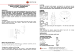
dh
domnick hunter
scientific
UHP Range of Zero Air Generators
dh, domnick hunter, OIL-X and Pneudri are registered
trademarks of domnick hunter limited.
domnick hunter limited has a continuous policy of product
development and although the Company reserves the right
to change specifications, it attempts to keep customers
informed of any alterations. This publication is for general
information only and customers are requested to contact our
Industrial Division Sales Department for detailed information
and advice on a products suitability for specific applications.
All products are sold subject to the Company’s standard
conditions of sale.
www.domnickhunter.com
a member of the domnick hunter group plc
dh
domnick hunter
scientific
domnick hunter limited
Dukesway, Team Valley Trading Estate,
Gateshead, Tyne and Wear,
England NE11 0PZ
Tel: +44 (0)191 402 9000
Telefax: +44 (0)191 482 6296
Copyright domnick hunter limited 2004
Stock No: 176270554 Rev 001
User Guide
DECLARATION OF CONFORMITY
Contents
Name of manufacturer or supplier: domnick hunter ltd.
Page No
Full postal address including country of origin:
Dukesway, TVTE, Gateshead, Tyne & Wear, NE11 0PZ
United Kingdom
1.
Safety Warnings
1
Place of issue: Gateshead
2.
Description
2
Description of product: Zero Air Generator
3.
Technical Specification
3
4.
Installation
4
5.
Service
6
6.
Troubleshooting
8
7.
Warranty
9
Name, type or model, batch or serial number:
UHP-10ZA, UHP-35ZA, UHP-50ZA, UHP-75ZA, UHP-150ZA, UHP-200ZA
Directives used
73/23/EEC 98/37/EC 89/336/EEC 97/23/EC 98/68/EEC 92/31/EEC
Standards used, including number, title, issue date and related documents
Generally In accordance with ASMEVIII Div.1:2004 and Pressure Equipment Directive
essential safety requirements
EN61000-6-1:2001, EN61000-6-3:2001, EN61000-3-2:2000, EN61000-3-3:1995
EN61010-1:2001
Conformity Assessment Route:
PED Article 3.3 SEP
Name of authorised representative
Barry Wade
Position of authorised representative
Business Systems Improvement Manager
Declaration
I declare that as the authorised representative, the above information in relation to the supply
/ manufacture of this product, is in conformity with the standards and other documents
following the provisions of the above Directives.
Signature of authorised representative
11
Declaration of Conformity
10
1. Safety Warnings
7. WARRANTY
Do not operate this generator until the instructions in this manual have been read and
understood by all personnel concerned.
This warranty applies to ZERO AIR GENERATORS and associated parts (the Equipment)
manufacturedand supplied by domnick hunter ltd (domnick hunter).
Retain this user guide for future reference.
Use of the ZERO AIR GENERATORS without the recommended inlet air quality or genuine
parts will expressly invalidate the warranty.
Caution: The operator of this unit is advised that if the equipment is used in a manner
not specified in this manual, the protection provided by the equipment may be
impaired.
When handling, installing or operating this unit, personnel must employ safe engineering
practices and observe all related regulations, health & safety procedures and legal
requirements for safety.
Most accidents that occur during the operation and maintenance of machinery are the result
of failure to observe basic safety rules and procedures. Accidents can be avoided by
recognising that any machinery is potentially hazardous.
domnick hunter can not anticipate every possible circumstance which may represent a
potential hazard. The warnings in this manual cover the most known potential hazards, but
by definition can not be all-inclusive.
Read manual
Should the Equipment be defective as to materials or workmanship, domnick hunter
warrants that it will remedy such defect. Where the Equipment is a ZERO AIR GENERATOR,
the warranty period will be 12 months from date of commissioning or 18 months from date of
manufacture, whichever is the earlier. In the case of Equipment other than a ZERO AIR
GENERATOR, the warranty period shall commence from the date of despatch. Should any
defect occur during the warranty period and be notified in writing to domnick hunter or its
authorised distributor within the said period, domnick hunter will, as its sole option, remedy
such defect by repair or provision of a replacement part, provided that the Equipment has
been used strictly in accordance with the instructions provided with each item of Equipment
and has been stored, installed, commissioned, operated and maintained in accordance with
such instruction and with good practice. domnick hunter shall not be under any liability
whatsoever under the warranty, if, before giving notification in writing to domnick hunter as
aforesaid, the Customer or any third party meddles, interferes, tampers with or carries out work
whatsoever (apart from normal maintenance as specified in the said instructions) in relation to
the Equipment or any part thereof.
Any accessories, parts and equipment supplied by domnick hunter but not manufactured by
domnick hunter shall carry whatever warranty the manufacturer has given domnick hunter
providing it is possible for domnick hunter to pass on such warranty to the
customer.
Risk of electrical shock
Pressurised components on system
General Warning
If the generator user employs an operating procedure, item of equipment or a method of
working which is not specifically recommended by domnick hunter the user must ensure
that the generator will not be damaged or made a potential hazard to persons or property.
To claim under the warranty, the goods must have been installed and continually maintained in
the manner specified in the User Guide. Our product support engineers are qualified and
equipped to assist you in this respect. They are also available to make repairs that may
become necessary in which event they will require an official order before carrying out the
work. If such work is to be the subject of a warranty claim, the order should be endorsed for
consideration under warranty.
Where Equipment is sold outside the UK mainland direct to the end user the warranty will cover
parts only. Any substitution of parts not manufactured or approved by domnick hunter will
expressly invalidate the warranty.
This product should be installed in accordance with the recommendations outlined in this
manual. Commissioning and service should be undertaken by a domnick hunter trained,
qualified and approved engineer to maintain warranty.
Extended warranty and tailored service contracts are available for this product. Please
contact your local domnick hunter sales office for a tailored service agreement to meet your
specific requirements.
Details of your nearest domnick hunter sales office can be found at
www.domnickhunter.com
1
10
6.
Troubleshooting
Fault Found
No power/green LED
will not illuminate
2. Description
Probable Cause
Remedy
Incorrect input voltage
Comments
Check mains voltage and
rating number plate for
voltage spec
Check fuse, replace if
necessary
Consult domnick
hunter service
department
Fuse blown
On/Off switch failure
Faulty Lamp
The inlet compressed air first passes through a 1.0 micron filter to remove any particulate.
After pre-filtration the air is passed over a heated palladium catalyst which converts methane
and oxygen in the air to carbon dioxide and water.
Consult domnick
hunter service
department
In normal operation, the Faulty heater
temperature
reading falls well below
Consult domnick
hunter service
department
0
420 C
domnick hunter zero air generators are designed to produce a supply of hydrocarbon free
air from a pre-treated (IS0 8573.1:2001 class 3.2.1) low pressure compressed air system so
eliminating the need for high pressure gas storage and disruption due to bottle changes and
subsequent recalibrations.
The unit has a safety
thermostat which will
switch off electrical
power to the unit if the
surface temperature of
the outer case exceeds
This catalytic action produces an ultra pure air stream with a residual hydrocarbon
concentration (as methane) of less than 0.1ppm. The gas exits the catalyst unit, and is then
cooled, via a cooling coil. Finally, the air passes through a 0.01 micron filter to remove any
particulate and water, which may be generated during the hydrocarbon removal phase.
o
Amber LED will not
illuminate
Faulty Lamp
Consult domnick
hunter service
department
Hydrocarbon level
>0.1ppm
Faulty temperature
controller
Consult domnick
hunter service
department
Faulty catalyst/heater
Consult domnick
hunter service
department
No power
Check power
Flow rate too high
Set flow rate correctly
60 C
Note – this LED will
intermittently
illuminate during
normal operation
Inlet air supply
Install pre-dryer and
hydrocarbon level too high filtration
Consult domnick
hunter service
department
Inlet air supply not to
ISO 8573.1:2001
class 3.2.1
Install pre-dryer and
filtration
Consult domnick
hunter service
department. If
condensate is drained
from the pre-filter then
inlet air supply is not to
required quality
replace cooling fan
Consult domnick
hunter service
department
Excessive downstream Cooling fan not operating
temperature
9
2
3. Technical Specification
3.1 Technical Data
5.1 Service Intervals
UHP-10ZA UHP-35ZA UHP-50ZA UHP-75ZA UHP-150ZA UHP-200ZA
Compressed Air
Inlet
Compressed Air
Outlet
Ambient and
Operating
Temperature
Inlet Pressure
1/8” Swagelok
1/4” Swagelok
1/8” Swagelok
1/4” Swagelok
+5 to + 40ºC
41 to 104 ºF
3 - 10barg
45 - 145psig
0.45 - 1.45Mpa
IS0 8573.1:2001 class 3.2.1
Inlet Air Quality
IP rating
IP20, NEMA 1, indoor use only.
115V, 50/60Hz, +/-10%
230V, 50/60Hz, +/-10%
Input Voltage
Flow rate (l/min)
3
(ft /h)
Power (W)
Relative Humidity
Maximum (m)
Altitude
(ft)
Installation
Overvoltage
Category
1
2.12
3.5
7.42
250
250
5.0
10.59
7.5
15.9
15
31.8
20
42.3
450
450
1000
<80% up to 31ºC
Then reduced by 3.33%/ºC up to 40ºC
2000
(6560)
1000
II
Pollution Degree
Service
Service Kit Number
Inlet Filter - All
504421110
A
Outlet Filter - All
504431110
B
UHP-10ZA 115V/60Hz
UHP-10ZA 230V/50Hz
UHP-35ZA 115V/60Hz
606272280
606272282
606272284
UHP-35ZA 230V/50Hz
UHP-50ZA 115V/60Hz
UHP-50ZA 230V/50Hz
606272286
606272288
606272290
2
3.2 Dimensions
Unit
UHP-10ZA UHP-35ZA UHP-50ZA UHP-75ZA UHP-150ZA UHP-200ZA
Height
mm
325
325
455
455
455
455
(inches)
12.8
12.8
17.9
17.9
17.9
17.9
Width
mm
342
342
342
342
342
342
(inches)
13.5
13.5
13.5
13.5
13.5
13.5
Depth
mm
400
400
400
400
400
400
(inches)
15.8
15.8
15.8
15.8
15.8
15.8
Weight
kg
10.8
10.8
16.1
16.1
16.1
16.1
(lbs)
23.8
23.8
35.5
35.5
35.5
35.5
Model No.
C
UHP-75ZA 115V/60Hz
606272292
UHP-75ZA 230V/50Hz
UHP-150ZA 115V/60Hz
606272294
606272296
UHP-150ZA 230V/50Hz
606272298
UHP-200ZA 115V/60Hz
606272300
UHP-200ZA 230V/50Hz
606272302
UHP 10-200ZA 115V/60Hz
UHP 10-200ZA 230V/50Hz
606260740
606260742
N.B. Ensure that zero air generator is fully depressurised, electrically isolated and allowed to
cool down before carrying out any service activities.
3
8
5. Service
5.1 Service Intervals
3.3 Configuration
Outlet
Controller
Cooling Fan
Filtration
Pipework
Generator
Filtration
Generator
Cooling Fan
Open manual drain valve to drain
any collected condensate.
Check pipework for leaks.
Service 8000
A
B
C
On/Off Switch
C
C
Electrical Connection
C
C
C
Replace inlet and outlet filters.
Recommended Service A
Replace catalyst assembly
Recommended Service B
Replace cooling fan
Recommended Service C
R
R
R
Temperature Display
Heater On Light
R - Replace
Typical Recommended Maintenance Intervals (Run Hours)
16000 24000 32000 40000 48000 56000 64000 72000
60-month
C
Check condition of electrical supply
cables and conduits
C - Check
24-month
Check POWER ON indicator located
on control panel is illuminated
Check HEATER ON indicator located
on control panel illuminates
intermittently.
Check fan rotation
12-month
Controller
6-month
Operation
3-month
Component
Weekly
Typical Recommended
Maintenance Interval
Daily
Description Of Maintenance Required
Inlet
80000
domnick hunter ltd and its distributors offer a comprehensive range of preventative
maintenance programmes, for further details contact your local domnick hunter distributor
or domnick hunter ltd direct (tel. 44 (0)191 402 9000) for further details
Power On Light
4. Installation
4.1 Unpacking
Care should be taken during unpacking to ensure that the Zero Air Generator is not
damaged
7
4
4.2 Installation Guidelines
4.3 Operation
1.
2.
Once the Zero Air generator is installed, the operating procedure is very simple:
Ensure that the zero air generator is correctly sized for the application.
Identify a suitable location for the zero air generator, ensuring the following:a) Environmental restrictions (refer to section 3.1 Technical Specification) are taken
into consideration.
b) The zero air generator should be located as close to the application as possible.
c) There is at least 150mm (6”) clearance, on both sides and rear of the zero air
generator, for ventilation.
d) Isolation valves should be fitted to the system, these must be accessible when the
zero air generator is installed.
N.B. It is recommended that a suitably rated pressure gauge is installed upstream of any
isolation valve.
e) The mounting surface is capable of supporting the weight of the zero air generator
(refer to section 3.2 Dimensions).
3
Ensure the inlet air supply is pre-treated to ISO 8573.1:2001 class 3.2.1.
•
Connect the power supply to the mains connector. Switch the generator on via the
mains ON/OFF switch. The green and amber lights should illuminate. The green LED
indicates power to the unit, with the amber LED indicating power to the heater.
•
Allow the catalyst to reach the operating temperature (approximately 60 minutes). Once
0
the correct operating temperature of 420 C is reached, the amber LED will
intermittently switch on and off showing the unit is now ready for operation.
•
Start the flow of compressed air through the system and allow it to stabilise. In normal
operation the amber LED should illuminate intermittently.
Caution
If the compressed air used to supply the zero air generator contains significant amounts of particulate,
moisture and oil, as would be expected if the compressed air is supplied straight from a compressor, a
small dryer should be installed upstream of the zero air generator to treat the inlet air to the required
standard of cleanliness (ISO8573.1:2001 class 3.2.1).
ISO 8573.1 : 2001 Class 3.2.1 equates to:
•
•
•
•
10,000 Solid Particle 0.5 - 1 micron/m3
500 Solid Particles 1 - 5 micron/m3
Water Vapour Pressure Dewpoint -40°C
Oil aerosol and vapour 0.01 mg/m3
In such instances a MIDAS type dryer is recommended. Please refer to the domnick hunter scientific
product brochure for further information on the MIDAS.
Further information on ISO 8573.1 can be found in the domnick hunter publication “A Guide to ISO
8573.1:2001 Air Quality Classes” (Stock Number: 17 400 4765).
Contact your local domnick hunter sales office or download a copy from our website
www.domnickhunter.com.
4
5
Check the rating plate for correct supply voltage and frequency.
It should be noted that the catalyst could become contaminated if compounds that
contain lead, phosphorous, sulphur, silicates or halocarbons are present in the inlet air
supply. If in doubt use an activated carbon filter at the inlet of the generator.
(contact domnick hunter for a suitable activated carbon filter).
N.B. Numerous dielectric tests are not recommended.
5
6