Transcript
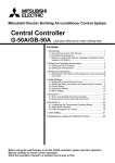
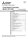
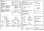
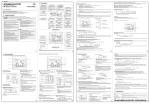
PAC-SE51CRA
PAR-F27MEA
User Guide
User Guide
17
10
4
18
14
19
20
23
15
12
16
13
6
1Hr
CENTRALLY CONTROLLED
ON
CHECK
OFF
11
CLOCK
FILTER
7
STAND BY
DEFROST
5
ERROR CODE
21
LIMIT TEMP
NOT AVAILABLE
TEMP
TE
1
ON/OFF
3
FILTER
1
CHECK
2
ON/OFF
REMOTE CONTROLLER
PAR - F27MEA
2
6
3
22
8
PAC-SER51CRA
7
5
Operation Buttons
Operation Buttons
1
2
3
TEST
TIMER SET
TEMP
`
9
1H
4
Display
OPERATION MODE - displays the operation status between
Cool/Dry/Auto/Fan/Heat.
Operation modes vary depending on the air conditioner unit,
Auto mode is the City Multi R2 and WR2 series only
4
ON/OFF - Switches between run and stop
The light flashes when a malfunction occurs
TEMPERATURE SETTING - Sets the room temperature:
Range of temperature setting:
Cool/Dry: 19ºC-30ºC
Heat: 17ºC-28ºC
Auto: 19ºC-28ºC
5
ON/OFF - switches between run and stop. The light flashes when a malfunction
occurs
10
ERROR - When an error is currently occurring on an air conditioner unit, the
affected unit and the error code are displayed
2
OPERATION MODE SWITCHING -Switches between Cool / Dry / Auto / Fan / Heat
Operation modes vary depending on the air conditioner unit.
Auto mode is for the City Multi R2 and WR2 series only
11
This lamp lights during operation, goes off when the unit stops and flashes when a
malfunction occurs
12
FILTER DISPLAY - indicates that it is time to clean the filter
13
DEFROST DISPLAY- this indicates when the defrost operation is performed
3
TEMPERATURE SETTING - Sets the room temperature:
Range of temperature setting:
Cool/Dry: 19ºC - 30ºC
Heat: 17ºC - 28ºC
Auto: 19ºC - 28ºC
14
INDOOR UNIT INTAKE TEMPERATURE - Measures the intake temperature of the
indoor unit when the indoor unit is operating
FAN SPEED SETTING - Models with 4 air flow speed settings: Hi/Mid-2/mid-1/Low
Models with 3 air flow speed settings. Hi/Mid/Low
Models with 2 air flow speed settings: Hi/Low
15
OPERATION MODE - displays the operation mode
4
16
LIMIT TEMP DISPLAY - displayed when the set temperature range is controlled by
remote controller function selection
AIR FLOW
DIRECTION SETTING 1H
Air flow direction angles 100% - 80% - 60% - 40%, Swing,
Louver ON/OFF
Air flow direction setting buttons vary depending on the model
17
TIMERS - displays the current time and timer set times
18
This displays the air direction
19
The selected fan speed is displayed
TIMER SELECTION BUTTON- Switches between:
one day timer: ON/OFF setting of one time on one day can be applied,
Daily timer: ON/OFF setting by the One day timer can be repeated for
everyday , Auto OFF timer: OFF timer can be set in a range from 30 minutes
to 4 hours
*Setting of auto OFF timer automatically activates OFF timer at the next operation
This function can be utilised to prevent the negligence of OFF setting
20
This indicates when a malfunction has occured in the unit which should be
checked!
21
This displays the selected temperature
22
This lamp lights when electricity is supplied to the unit
23
SENSOR DISPLAY - displayed when the remote controller sensor is used
POWER DISPLAY - displayed while the remote control is powered on
5
FAN SPEED SETTING - Models with 4 airflow speed settings: Hi/Mid-2/Mid-1/Low
Models with 2 airflow speed settings: Hi/Low
CHECK - displayed together with the address of the malfunctioning unit (3 digits)
and an error code (4 digits )
6
Displays set temperature
7
Display
1
6
7
This is the Lossnay interlock button
8
This sets the current time, timer start and stop times
9
This resets the Filter service indication display
PAR-20MAA
PAR-S27AA
User Guide
User Guide
25
23
26
11
24
10
12
13
22
14
9
1Hr
CENTRALLY CONTROLLED
ON
CHECK
OFF
15
CLOCK
CENTRALLY CONTROLLED
FILTER
ON
CHECK MODE
TEST RUN
STAND BY
DEFROST
ERROR CODE
TTEMP
20
FILTER
16
FUNCTION
NOT AVAILABLE
1Hr
OFF
CLOCK
CHECK
CHECK MODE
STAND BY
DEFROST
ON/OFF
INDOOR UNIT
ADDRESS No.
ERROR CODE OA
UNITADDRESS No.
NOT AVAILABLE
21
TEST RUN
1
1
8
1H
2
CLOCK ON
1H
OFF
FILTER
FILTER
2
7
CHECK
TEST
CHECK
TIMER SET
3
REMOTE CONTROLLER
PAR-20MAA
TTEMP
TIMER SET
TEST RUN
REMOTE CONTROLLER
PAR-S27AA
4
3
4
5
5
6
17
18
19
Operation Buttons
IF YOU ARE TOO
HOT PRESS
Operation Buttons
1
2
IF YOU ARE TOO
COLD PRESS
Heating (Ideal Temp 20ºC)
Cooling (Ideal Temp 23ºC)
Dry Mode - DO NOT USE
Auto (Ideal Temp 21ºC)
3
This switches between continuous operation and the timer operation
12
2
Press this button to switch between the cooling, dry (dehumidify),
automatic and heating modes
This sets the room temperature, The temperature setting can be performed in 1ºC
intervals. Setting range: Cooling 19ºC to 30ºC - Heating 17ºC to 28ºC
This indicates when the unit is controlled by optional features such as a central
control type remote controller
13
14
This indicates when a malfunction has occurred in the unit which should be checked
This button selects between clock, timer start and timer stop
15
The standby symbol is only displayed from the time the heating operation starts untill the
heated air begins to blow
3
Fan only - DO NOT USE
SET IDEAL TEMPERATURE:
Heating 20ºC
Display
1
TURN UNIT ON\OFF
MODE KEY:
4
5
6
7
`8
This switches the louvre motion ON and OFF
16
This indicates when the defrost operation is performed
17
This adjusts the angle of the air flow direction
18
19
20
21
This indicates when the continuous operation and time operation modes are set. It
also displays the time for the timer operation at the same time as when it is set
This displays the selected temperature
10
This switches between the operation and stop modes each time it is pressed,
the lamp on this button lights during operation
This sets the unit fan speed
11
These buttons are used to set the current time, timer start and stop times when
selected by button 4 above
9
TIMER - already fixed (do not adjust)
5
FAN SPEED - Leave in low speed
6
CASSETTE UNITS ONLY - Fix swing position
This indicates the operation mode
This resets the filter cleaning indication display
This is the Lossnay interlock button
This lamp lights when electricity is supplied to the unit
This lamp lights when the filter needs to be cleaned
This display lights in the check mode or when a test operation is performed
22
This lamp lights during operation, goes off when the unit stops and flashes when a
malfunction occurrs
23
The temperature of the suction air is displayed during operation. The display range is 10º to
35ºC. The display flashes 10ºC when the actual temperature is less than 10º
and flashes 35ºC when the actual temperature is greater than 35ºC
Cooling 23ºC
4
6
24
25
26
The selected fan speed is displayed
This displays the air direction
The current time, start time and stop time can be displayed in ten second intervals by
pressing the time setting button. The start time or stop time is always displayed during
the timer operation