1
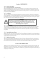
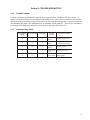
Owners Manual
For
Dry Vacuum Pumps
Models:
2560
2561
2565
2580
2581
2585
WARNING
Not recommended for pumping acid, base or
organic vapors or gases.
WARNING
Be sure to properly identify intake and discharge
before using pump. See section 2.5
Welch Rietschle Thomas
7301 North Central Avenue
Skokie, IL 60077
Phone: (847) 676-8800
Fax: (847) 677-8606
E-Mail: [email protected]
Web-Page: www.welchvacuum.com
Part No. 67-0974R2.8
Printed in the U.S.A
INSTRUCTION
WARNING AND CAUTION
PLEASE READ BEFORE OPERATION
While reading your manual, please pay close attention to areas labeled
WARNING AND CAUTIONS. The description of each is found below.
WARNING
Warnings are given where failure to observe instruction
could result in injury or death to people
CAUTION
Cautions are found where failure to observe the instruction should
result in damage to the equipment, associated equipment and process.
These units conform to the SI International system of units of measurement.
The following symbols (with recommendations of IEC1010) of warning will be found on the pump.
Caution - refer to accompanying documents
Caution - risk of electrical shock
Caution - hot surface
WARNING
Motor includes a self reseting thermal cut-out and the pump
could restart without actuation under fault condition.
2
Section 1:
Safety Information
Section 2:
Installation
Section 3:
Operation
Section 4:
Maintenance
Section 5:
Troubleshooting
Section 6:
Specifications
Speed Curves
Dimensional Drawings
Parts List and Exploded View
Application Information
Warranty
Welch Rietschle Thomas
Read and understand the following information and instructions included with your
Welch Dry Vacuum Pumps before using. This information is for your safety
and to prevent damage to the pumps.
3
Section 1: SAFETY INFORMATION
I.10 CAUTION: To prevent injury....
I.11
I.12
I.13
I.14
I.15
I.16
Never operate this product if it has a damaged cord or plug. If it is not working properly, has been
dropped, damaged or has fallen into water, please return the product to a Welch service center for
examination and repair.
Keep the cord away from the heated surfaces.
Never block any air openings or place it on a soft surface where the openings may be blocked.
The air openings are for ventilation of the motor inside the housing. Keep all air openings free of lint,
dirt and other foreign objects.
The PTFE pump is thermally protected and can automatically restart when the protector resets.
Always disconnect power source before servicing.
Wear safety glasses or goggles when operating this product.
Use only in well ventilated areas. The motor is fan cooled enclosed in a shell.
WARNING
Do not operate the pumps in an atmosphere
containing flammable or explosive gases/vapors.
WARNING
Never block the exhaust port. If the exhaust is blocked, pressure
will build-up in the pump with the potential of the pump head
bursting and causing possible injury to personnel in the area.
I.17
I.18
All electrical products generate heat. To avoid serious burns never touch unit during or immediately
after operation.
Be sure to properly identify intake and discharge before using pump. See Section II-5.
I.20 CAUTION: To reduce risk of electrical shock....
I.21 Do not disassemble. Disassembly or attempted repairs if accomplished incorrectly can create
I.22
I.23
I.24
I.25
I.26
I.27
I.28
I.29
electrical shock hazard. Refer servicing to qualified service agencies only:
Call (847) 676-8800 Ext. 1
Unit is supplied with a three pronged plug. Be sure to connect pump to a properly grounded
outlet only.
WARNING: To reduce risk of electricution…
Do not use this product in or near area where it can fall or be pulled into water or other liquids.
Do not reach for this product if it has fallen into liquid. Unplug immediately.
Never operate this product outdoors in the rain or in a wet area.
DANGER: To reduce risk of explosion or fire…
Do not use this pump near explosive atmospheres or where aerosol (spray) products are being used.
Do not use this product near flames.
WARNING
Failure to observe the above safety precautions could result
in severe bodily injury, including death in extreme cases.
4
Section 2: INSTALLATION
2.10
Introduction
This manual has been compiled not only for the care and maintenance of the Welch Dry Vacuum System now
in your possession, but as a helpful reference and guide to prevent many problems which can occur if used
improperly.
2.11
Unpacking
Carefully remove the Dry Vacuum System from the shipping carton. Preserve all paperwork for future
reference. If damage has occurred from shipment a claim must be filed with the carrier immediately; preserve
the shipping carton for inspection by the carrier. If you are required to communicate with your dealer or
Welch Vacuum be sure to include your order numbers for quick identification. Do not return the system to
the factory without first calling for a returned goods number. Call (847) 676-8800 Ext. 1
2.12
System Mounting
Rubber feet are attached to the pump. Rubber feet are excellent for applications involving a semi-flexible
surface such as a bench top; they help to isolate noise and eliminate creeping.
2.13
System Location and Enviromental Condition
The Dry Vacuum System should be located preferably in a clean, dry and well ventilated area. Please be sure
not to block the ventilation ports located on the metal shell. The pump should be placed where the surrounding temperature remains between 10°C and 40°C (50°F and 104°F). Always check to insure the location
chosen is protected from direct or indirect moisture contact. The pump should be located as closely to its
system in order to utilize it most efficiently. The pump is rated for indoor use only. Maximum altitude 2000
meters. Operating temperature range 5°C to 40°C. Maximum relative humidity of 80% for temp. up to 31°C
decreasing to 50% at 40°C. Rated for ±10% of supply voltage. Pollution Degree2, Installation Category II.
WARNING
Don’t operate this pump in an atmosphere
containing flammable or explosive gases or vapors.
WARNING
The motor is thermally protected and will automatically
restart unexpectedly when the overload device resets.
2.14
Inlet and Outlet Provisions
A inlet hose barb which accepts ¼” I.D. hose makes it easy to connect the system to your concentrator, rotary
evaporator or gel dryer. Since the vacuum system operates in the viscous flow regime, the small diameter of
the hose will generate minimal conductance loss. For best results, Welch recommends the length of the
tubing between the pump and the apparatus be kept as short as possible. Hose clamps should be used to hold
the hose in place.
The hose barb in the outlet port of the pump accepts ¼” ID hose. A vent line can be attached to the outlet
hose barb which allows gases and vapors pumped through the pump to be piped to a fume hood. Be sure to
call Welch technical service prior to start-up at (847) 676-8800 if you have any questions.
WARNING
Never Block The Outer Port. If the outlet is blocked, pressure will
buildup in the pump which can lead to the pump head bursting
creating the potential of serious injury. Remove plug from outer port.
5
2.20
2.21
Electrical Power
Power Source Review
Review the power source and the voltage rating on the units serial number tag to be sure they agree in voltage,
phase and frequency. Serious damage may occur to the system if it is connected to an improper voltage. All
Welch systems must be grounded. Grounding reduces the risk of electric shock in the event of an electrical
short circuit. The plug must be plugged into an outlet properly grounded. Consult your local electrical codes
if you have doubts.
2.22
Overload Protection
The motor manufacturer makes motor thermal overload protection availeble as an aid to minimize motor
failure. Overload protection is a standard feature on both 50/60Hz single-phase motors. The motors have
automatic overload protection. Automatic reset protection is designed to reset itself after a predetermined
cooling period. If the fault to the drive remains unaltered, the motor will cycle on and off until fault is corrected.
2.23
Identification Symbols
2.24
Grounding Instructions
This product should be grounded. In the event of an electrical short circuit, grounding reduces the risk of
electric shock by providing an escape wire for the electric current. This product is equipped with a cord
having a grounding wire with a grounding plug. The plug must be plugged into an outlet that is properly
installed and grounded in accordance with all local codes and ordinances.
This adapter shown in Figure B and Figure C is not acceptable in Canada.
DANGER
Improper installation of the grounding plug
can result in a risk of electrical shock.
If repair or replacement of the cord or plug is necessary, do not connect the grounding wire to either flat blade
terminal. The wire with insulation having an outer surface that is green with or without yellow stripes is the
grounding wire.
Check with a qualified electrician or serviceman if the grounding instructions are not completely understood, or if
in doubt as to whether the product is properly grounded. Do not modify the plug provided; if it will not fit the
outlet, have the proper outlet installed by a qualified electrician.
This product is for use on a nominal 120V circuit, and has a grounding plug that looks like the plug illustrated in
Sketch A in Figure #1. A temporary adapter, which looks like the adapter illustrated in sketches Band C, may be
used to connect this plug to a 2-pole receptacle as shown in sketch B if a properly grounded outlet is not available.
The temporary adapter should be used only until a properly grounded outlet (Sketch A) can be installed by a
qualified electrician. The green colored rigid ear, lug, etc. extending from the adapter must be connected to a
permanent ground such as a properly grounded outlet box cover. Whenever the adapter is used, it must be held in
place by a metal screw.
2.25
Extension Cords
If necessary to use an extension cord, use a 3-wire extension cord that has a 3-blade grounding plug, and a 3slot receptacle that will accept the plug on the product. Make certain your extension cord is in good
condition. Make certain your extension cord wire size is not less than 18 gauge for 25 feet, 16 gauge for 50
feet, and 14 gauge for 100 feet. An undersized cord will cause a drop in line voltage resulting in loss of
power and overheating. If in doubt, use the next heavier cord. The smaller the gauge number, the heavier the
cord.
6
2.26
Dial Vacuum Gauge
A dial vacuum gauge is incorporated in the vacuum system. The dial gauge is located in the top front section
of the system. The dial vacuum gauge is commonly used to indicate vacuum level when operating in the
rough vacuum range (0 to 29.9”Hg) Dial vacuum gauges give negative pressure - that is pressure below
atmospheric. The reference point for the gauges is atmospheric pressure. Please keep in mind that atmospheric pressure tends to vary from day to day. As a result of this variability, a dial vacuum gauge will
indicate slightly different maximum vacuum readings from day to day.
2.27
Vacuum Level Regulation
Vacuum level regulation is accomplished with an adjustable bleed valve. The adjustable bleed valve allows
close control of pressure in your apparatus. Pressure may be set between roughly atmospheric pressure and
the maximum vacuum obtainable (9 torr, 29.6 in Hg).
2.28
Vacuum Connections
All Dry Vacuum Pumps come with intake and discharge hose barbs which accept 3/8” ID rubber pressure/
vacuum hose. Hose clamps should be used to hold the hose in place. Since all six models operate in the
viscous flow range, the small diameter of the hose will generate minimal conductance loss. For best results,
Welch recommends the length of the tubing between the pump and the chamber be kept as small as possible.
2.29
Vacuum Gauges
Typical in the rough vacuum range, a dial vacuum gauge is used to measure pressure in mm, Hg or inches of
Hg. The dial vacuum gauge gives negative pressure – that is pressure below atmospheric. The reference
point for the vacuum gauge is atmospheric pressure.
Please keep in mind that atmospheric pressure tends to vary from day to day. As a result of variability, the
dial vacuum gauge will indicate slightly different maximum vacuum readings from day to day.
2.30
2.31
Traps
The need for a Trap
2.32
The care of a Trap
The pumps will handle humid air. All wetted aluminum parts are treated for corrosion protection from moisture.
All other wetted parts are stainless steel. If there is a chance liquid may be drawn from the process under
evacuation, Welch recommends a liquid trap be placed between the process and the pump. A simple liquid trap is
a filtering flask.
When a heavy load of water vapor is evolved from the vacuum process, a cold trap is recommended to help
prevent damage to the pump mechanism. The cold trap, immersed in a suitable Dewar flask, is installed so
that the water vapor may come in contact with the surfaces of the trap and condense. Commonly used
refrigerants are liquid nitrogen or dry ice and acetone or alcohol. Dry ice provides sufficient cooling to freeze
out most heavy water vapor loads. A variety of cold traps are available from Welch.
The symptom of a high water vapor load is if you have droplets coming out of the exhaust port. If you see
droplets of water, Welch recommends you use a cold trap to capture the water before entering the pump or
dilute the water vapor stream by adding dry nitrogen to the gas flow. Please call our customer service
department for additional information at (847) 676-8800 Ext. 1.
When using a cold trap the refrigerant should be maintained at a high level in the flask to keep the trap at a
uniformly low temperature. If the trap is re-warmed it may allow re-evaporation of the condensate. The
refrigerant add tube on the liquid nitrogen trap should not be obstructed as the refrigerant boil-off can produce
dangerously high pressures. If the trap becomes saturated it should be disconnected from the system, drained
and cleaned. An increase in pressure in the vacuum system will normally indicate that the trap has become
saturated. To clean the trap, remove the trap from the system and allow the trap to warm up and rinse off the
condensate with a suitable solvent in a fume hood. Thoroughly clean and dry the trap before reinstalling into
the system.
7
Section 3: OPERATION
3.10
3.11
Starting Procedures
Starting a Welch Dry Vacuum Pump
Before attaching the pump to a system it is well to familiarize yourself with the function and action of the
pressure vacuum pump that you have acquired. Review the power requirements as described in Section 2.6.
Welch recommends running the pump for a few minutes to warm up before use. The warm-up improves the
pump’s ability to handle humid air.
3.12
Cleanliness
Take every precaution to prevent foreign particulates from entering the pump. Particulates will damage the
pump’s performance. If you find that particulates will come off the process during evacuation, a particle trap
in the foreline will work. A simple, inexpensive trap may be made by placing glass wool in a glass or plastic
tube. Screens must be inserted to hold the glass wool in place.
WARNING
The Pump is not recommended for pumping acid, base or organic vapors or
gases. Serious damage to the pump will shorten the pump’s service life.
In addition, pumping flammable vapors or gases can lead to serious safety
hazard leading to fire or explosion.
3.13
Leak Detection
The importance of eliminating all leaks in a vacuum system is obvious. The pump must remove this added
volume of leaked gas to maintain the desired vacuum. Leaks for these pumps can be located by slightly
pressuring the system and painting the suspected area with a thick soap solution. Escaping air will produce
soap bubbles.
3.14
Operating Pressure Range
Models 2560, 2561, 2565, 2580, 2581 and 2585 Dry Vacuum Pumps are designed to be run from atmospheric
to their maximum vacuum level on the intake side. Consult the Specification Table in the back of this manual
for the ratings for your specific model.
3.15
Shutdown Procedures
After use, Welch recommends the pump be run for about 2 minutes disconnected from the vacuum process.
The air pumped through the mechanism will purge out water vapor or droplets of water condensate that may
have formed on the inside of the pump. This purge of the pump mechanism helps prevent corrosion.
Section 4: MAINTENANCE
Welch dry pressure\vacuum units are 100% oil-free. The pump employs a non-lube piston and cylinder. No
maintenance is necessary for the bearings. All bearings are sealed and permanently lubricated. Lubrication
should not be attempted. The units are built for continuous duty operation with the quietness and durability of
a diaphragm, but with piston p
8
Section 5: TROUBLESHOOTING
5.10
Vacuum Problems
Leakage, contamination and unusual outgassing are the general causes of problems with poor vacuum. To
operate at maximum efficiency a system must be thoroughly clean. If the system is completely clean and free
from leaks, and unwarranted vacuum problems still exist, the pump should be checked. A simple criterion for
the condition of the pump is the determination of its maximum vacuum capability. This can be accomplished
by blocking of the intake and reading the vacuum level on the gauge (See Section 2.8).
5.11
Troubleshooting Guide
Poor Pumping
Spe e d
Poor Vacuum
Loud Unit
Pos s ible
Caus e s
X
X
X
Damaged
Valves
Replace flapper valves
X
X
X
Debris in
Valves
Remove debris and
check for valve damage
X
X
X
Damaged
Gasket
Replace gasket
X
X
X
Loose Head
Screw
Tighten head screw
X
X
Loose Fitting
Tighten fittings
Corre ctive Action
9
Section 6: SPECIFICATIONS
6.10
Pump Specifications Chart
We lch M ode l
2560
2561
2565
2580
2581
2585
1.6 (45)
2.3 (38)
(60)
(50)
3.1 (88)
4.4 (73)
3.5 (99)
4.9 (83)
(100)
(83)
7.1 (201)
10 (168)
Ultimate Pressure,
Torr
(mbar)
7.5
(10)
5
(6.7)
60
(80)
9
(12)
5
(6.7)
60
(80)
Maximum Vacuum, in. Hg
29.6
29.8
27.6
29.6
29.8
27.6
Motor Horsepower
Horsepower
(watts)
1/3
(250)
1/3
(250)
1/3
(250)
1/3
(250)
1/3
(250)
1/3
(250)
Tubing needed,
I.D. in Inches
(I.D. in mm)
3/8
(10)
1/4
(7)
3/8
(10)
3/8
(10)
3/8
(10)
3/8
(10)
Intake & Exhaust Thread, NPT
1/4
1/4
1/4
3/8
3/8
3/8
16.5
(7.5)
16.5
(7.5)
16.5
(7.5)
22.5
(10.3)
24.5
(10.3)
24.5
(10.3)
11.1 (28.2)
6.5 (16.5)
9.1 (23.1)
17.3 (43.9)
6.5 (16.5)
10.5 (26.7)
15.0 (38.1)
10.0 (25.4)
10.0 (25.4)
11.1 (28.2)
9.2 (23.4)
11.0 (27.9)
17.0 (43.2)
7.5 (19.1)
12.0 (30.5)
17.0 (43.2)
7.5 (19.1)
12.0 (30.5)
21.5
(9.7)
21.5
(9.7)
21.5
(9.7)
27.5
(12.5)
29.5
(12.5)
29.5
(12.5)
19.5 (49.5)
20.5 (52.0)
16.0 (40.6)
19.5 (49.5)
20.5 (52.0)
16.0 (40.6)
19.5 (49.5)
20.5 (52.0)
16.0 (40.6)
19.5 (49.5)
20.5 (52.0)
16.0 (40.6)
19.5 (49.5)
20.5 (52.0)
16.0 (40.6)
19.5 (49.5)
20.5 (52.0)
16.0 (40.6)
Catalog Number
Wired for 115V, 60Hz, 1Ph
With N. American 115V Plug
2560B- 01
2561B- 24
2565B- 01
2580B- 01
2581B- 24
2585B- 01
Catalog Number w/ Jar & Regulator
Wired for 115V, 60Hz, 1Ph
With N. American 115V Plug
2560B- 50
2561B- 50
2565B- 50
2580B- 50
2581B- 50
2585B- 50
Catalog Number
Wired for 220V, 50Hz, 1Ph
With Cont. Euro (Schuko) Plug
2560C - 02
2561C- 24
2565C - 02
2580C - 02
2581C- 24
2585C - 02
Catalog Number w/ Jar & Regulator
Wired for 220V, 50Hz, 1Ph
With Cont. Euro (Schuko) Plug
2560C - 50
2561C- 50
2565C - 50
2580C - 50
2581C- 50
2585C - 50
Catalog Number
Wired for 100V, 50/60Hz, 1Ph
With a Plug
N/A
2561C- 25
N/A
2580C - 05
2581C- 25
N/A
Catalog Number w/ Jar & Regulator
Wired for 100V, 50/60Hz, 1Ph
With a Plug
N/A
2561C- 56
N/A
2580C - 56
2581C- 56
N/A
Free Air Displacement
CFM (L/min)@60Hz
M3/hr (L/min)@50Hz
Weight,
lbs
(K g)
O verall Dimension,
L in. (cm)
W in. (cm)
H in. (cm)
Shipping Weight,
lbs
(K g)
Shippingl Dimension,
L in. (cm)
W in. (cm)
H in. (cm)
10
6.11
Pumping Speed Curves
11
6.12
12
Dimensional Drawings
Pump M ode l
A
B
C
D
2560
12 . 5 0
8.75
6.50
5.25
2561
11.67
9.78
7 . 19
2565
11.25
8.75
2580
13 . 2 5
G
H
I
J
K
L
M
N
10.00 8.25
7.00
6.62
2.88
0.81
3.88
0.81
3.50
5.65
5.38
9.61
8.25
7.58
7.17
3.09
0.75
4.50
0.75
3.50
6.00
6.50
5.25
10.00 8.25
7.00
6.62
2.88
0.81
3.88
0.81
3.50
5.65
11.69
7.60
5.25
10.50 8.50
9.50
8.75
3.06
0.75
2.7
0.75
4.50
6.00
2581
12.50 12.00
7.60
5.25
10 . 5 0 8 . 5 0
8.85
8.50
3.06
0.59
2.7
0.59
4.50
6.00
2585
12.00
7.37
5.25
10.50 8.50
9.50
8.75
3.06
0.75
4.62
0.75
4.50
6.00
11.69
E
F
6.13
Parts List and Exploded View for 2560
Ite m
N o.
Part No.
De s cription
Qty
Se rvice Kit
2565K-03
Se al Se rvice Kit
2565K-04
Fe e t Se rvice Kit
2500K-04
1
2565K - 01
Connecting Rod Assembly
1
2
---
---
2
61- 8726 *
Handle Screw
2
2
---
---
3
61- 3314 *
O- Ring, Connector Tube
2
4
4
---
4
61- 3315 *
Head Screw
10
10
---
---
5
2565K - 02
Valve Plate Assembly
2
2
---
---
6
61- 3316 *
O- Ring, Valve Plate
2
2
2
---
7
61- 3317 *
O- Ring, Cylinder
2
2
2
---
8
1412C
Muffler
1
1
---
---
9
6 6 - 0 16 0 *
Feet, Suction Cup
4
---
---
4
* Note: These parts are not available seperatly, but are supplied within kits sown in last three colums.
13
6.14
Parts List and Exploded View for 2561
Ite m
N o.
Part No.
Qty
Se rvice Kit
2561K-03
1
61- 3603 *
Piston Cup
2
2
---
---
2
61- 3604 *
Cup Retainer Screw
2
2
---
---
3
61- 3441 *
Cylinder Sleeve
2
2
---
---
4
62- 1052 *
O- Ring, Gasket
2
2
2
---
5
61- 3607 *
Head Screw
6
6
---
---
6
66- 0288 *
Intake Valve, Intake Stage
1
1
1
---
7
66- 0289 *
Intake/Exhaust Valve,
Intake and Exhaust Stage
3
3
3
---
8
62- 1050 *
O- Ring, Cylinder Sleeve
2
2
2
---
10
66- 0160 *
Feet, Suction Cup
4
---
---
4
De s cription
Se al Se rvice Kit Fe e t Se rvice Kit
2561K-04
2500K-04
* Note: These parts are not available seperatly, but are supplied within kits sown in last three colums.
14
6.15
Parts List and Exploded View for 2565
Ite m
N o.
Part No.
De s cription
Qty
Se rvice Kit
2565K-03
Se al Se rvice Kit Fe e t Se rvice Kit
2565K-04
2500K-04
1
2565K - 01
Connecting Rod Assembly
1
2
---
---
2
61- 8726 *
Handle Screw
2
2
---
---
3
61- 3314 *
O- Ring, Connector Tube
4
4
4
---
4
61- 3315 *
Head Screw
10
10
---
---
5
2565K - 02
Valve Plate Assembly
2
2
---
---
6
61- 3316 *
O- Ring, Valve Plate
2
2
2
---
7
61- 3317 *
O- Ring, Cylinder
2
2
2
---
8
1412C
Muffler
1
1
---
---
9
6 6 - 0 16 0 *
Feet, Suction Cup
4
---
---
4
* Note: These parts are not available seperatly, but are supplied within kits sown in last three colums.
15
6.16
Parts List and Exploded View for 2580
Ite m
N o.
Part No.
De s cription
Qty
Se rvice Kit
2585K-03
Se al Se rvice Kit Fe e t Se rvice Kit
2585K-04
2500K-04
1
2585K - 01
Connecting Rod Assembly
2
2
---
---
2
61- 0373 *
O- Ring, Valve Plate
2
2
2
---
3
61- 0374 *
O- Ring, Connector Tube
2
4
4
---
4
61- 0375 *
Head Screw
8
8
---
---
5
66- 0160 *
Feet, Suction Cup
4
---
---
4
6
2585K - 02
Valve Plate Assembly
2
2
---
---
7
61- 3286 *
O- Ring, Cylinder
2
2
2
---
8
1412C
Muffler
1
1
---
---
* Note: These parts are not available seperatly, but are supplied within kits sown in last three colums.
16
6.17
Parts List and Exploded View for 2581
Ite m
N o.
Part No.
Qty
Se rvice Kit
2581K-03
Se al Se rvice Kit
2581K-04
Fe e t Se rvice Kit
2500K-04
2
66- 0258 *
Piston Cup
2
2
---
---
4
66- 0284 *
Cylinder Sleeve
2
2
---
---
5
61- 3286 *
O- Ring, Cylinder
2
2
---
---
6
66- 0290 *
Intake Stage, Intake Valve
1
1
1
---
8
66- 0271 *
Exhaust Valve
2
2
2
---
10
62- 3624 *
O- Ring, Valve Plate
2
2
2
---
13
66- 0276 *
O- Ring, Connector Tube
2
2
2
---
14
62- 0375 *
Head Screw
8
8
---
---
18
66- 0291 *
Exhaust Stage, Intake Valve
1
1
1
---
19
66- 0160 *
Feet, Suction Cup
4
---
---
4
De s cription
* Note: These parts are not available seperatly, but are supplied within kits sown in last three colums.
17
6.18
Parts List and Exploded View for 2585
Ite m
N o.
Part No.
De s cription
Qty
Se rvice Kit
2585K-03
Se al Se rvice Kit Fe e t Se rvice Kit
2585K-04
2500K-04
1
2585K - 01
Connecting Rod Assembly
2
2
---
---
2
61- 0373 *
O- Ring, Valve Plate
2
2
2
---
3
61- 0374 *
O- Ring, Connector Tube
4
4
4
---
4
61- 0375 *
Head Screw
8
8
---
---
5
6 6 - 0 16 0 *
Feet, Suction Cup
4
---
---
4
6
2585K - 02
Valve Plate Assembly
2
2
---
---
7
61- 3286 *
O- Ring, Cylinder
2
2
2
---
8
1412C
Muffler
1
1
---
---
* Note: These parts are not available seperatly, but are supplied within kits sown in last three colums.
18
Section 7: APPLICATION INFORMATION
7.10
Vacuum System for Cell Harvesting:
2565B-50
2565C-50
2585B-50
2585C-50
System Components
7.11
Qty.
2565
2585
D e s cription
1
2565B- 01 2585B- 01 Pump, 115V, 60Hz, 1Ph
or 1 2565C- 02 2585C- 02 Pump, 230v, 50/60Hz, 1 Ph
7.12
1
61- 3576
61- 3576
Jar Assembly, Machined
1
61- 5142
61- 5142
N eedle Valve Miniature
1
61- 5148
61- 5148
Instrument K nob, Fluted Black
1
62- 0354
62- 0354
Hose Barb, 3/8" N PT
1
66- 0136
66- 0136
Barb Male Straight K ynar
1
62- 1066
62- 0372
N ipple 3/8" x 1"
N ipple Hex Reducing 3/8" x 1/4"
1
or 1
61- 3494
71- 1295
61- 3494
71- 1295
Vacuum Gauge, kPa/ in Hg
Vacuum Gauge, cm Hg/ in Hg
System Operation
The vacuum system provides high throughput flow wich allows up to 96+ sample system to be handled. The
attached inlet trap is provided to inhibit the accidental ingestion of liquid into the pump.
Vacuum level is preset at 26”Hg when the inlet is plugged with a rubber stopper. The vacuum gauge provided
allows to check the vacuum level -- that is pressure below atmospheric. The reference point for the vacuum
gauge is atmospheric pressure. Please keep in mind that atmospheric pressure tends to vary from day to day.
As a result of this variability, the dial vacuum gauge will indicate slightly different maximum vacuum
readings from day to day.
The preset vacuum level may be adjusted by opening or closing the orifice. A small leak through the orifice is
provided to allow easy restart of the pump if you are turning off then immediatly turning on the pump as is
found with some cell harvesting applications.
By turning clockwise the screw located on top of the orifice, the vacuum level can be dropped to as low as
27.6”. The deeper vacuum is particulary useful for removing sticky or viscous substance. If you close off the
orifice, please keep in mind this will lead to restart problems if you are turning off then imediatly turning on
the pump. If you encounter a restart problem after closing the orifice, you will need to incorporate into your
procedure bringing the cell harvester up to atmospheric prior to restarting of the pump.
19
7.20
Vacuum System for Vacuum Chamber,
Glove Box, Annular Space & Transfer Line
2561B-50
2561C-50
2561C-56
2581B-50
2581C-50
2581C-56
System Components
7.21
Qty.
2561
2581
D e s cription
1
or 1
or 1
2561B- 24
2561C- 24
2561C- 25
2581B- 24
2 5 8 1C - 2 4
2 5 8 1C - 2 5
1
6 1- 3 5 7 6
61- 3576
Jar Assembly, Machined
1
61- 5142
61- 5142
N eedle Valve Miniature
1
61- 5148
61- 5148
Instrument K nob, Fluted Black
1
62- 0354
62- 0354
Hose Barb, 3/8" N PT
1
6 6 - 0 13 6
6 6 - 0 13 6
Barb Male Straight K ynar
1
62- 1066
62- 0372
62- 1066
N ipple 3/8" x 1"
N ipple Hex Reducing 3/8" x 1/4"
Pump, 115V, 60Hz, 1Ph
Pump, 230V, 50/60Hz, 1 Ph
Pump, 100V, 50/60Hz, 1 Ph
1
61- 3494* 61- 3494* Vacuum Gauge, kPa/ in Hg
or 1 71- 1295** 71- 1295** Vacuum Gauge, cm Hg/ in Hg
* used on 2561B & 2581B
** used on 2561C & 2581C
7.22
System Operation
Welch’s new portable oil-free general utility roughing pumps provide continuous, reliable vacuum that your
vacuum chamber, glove box, annular space and transfer line applications require. The pumping mechanism
is an economical twin head oil-free Wob-L® known for reliability and durability. These rugged pumps
handle 20,000 plus roughing cycles – from atmospheric to 5 Torr – before needing seal maintenance.
The pumps come completely equipped and ready to use. An inlet trap to help prevent ingestion of fluids into the
pump, a dial gauge for continuous vacuum level monitoring, and a vacuum regulator to adjust vacuum levels.
Just plug it in and you’ re up and running.
Choose Model 2581B-50 for evacuating vacuum ovens, annular spaces, transfer lines and purging a glove box
up to 30 cubic feet. For Vacuum Ovens, Model 2561B-50 is suited for 1.5 cubic foot ovens or smaller and Model
2581B-50 can be used for up to 3.5 cubic feet.
The pumping speed of the 2561 and 2581 at rough vacuum levels is equal to oil-seal rotary vane pumps of similar
size. This makes the 2561 and 2581 an economical, oil-free solution for replacing oil-seal rotary vane pumps.
These pumps are therefore highly recommended for standard duty laboratory applications, general vacuum work
and where quick roughing of a chamber is needed.
The 2581 and 2561 pump Models are for use in standard duty applications. This means that they are not recommended for pumping acidic, basics or organic vapors or gasses. If you are looking for a pump to handles these
types of conditions, contact a Welch representative and they will be able to assist you in selecting the correct
pump for your application.
20
21
WARRANTY
This Welch Vacuum product is warranted to be free from defects in material and workmanship. This liability
of Welch Rietschle Thomas under this warranty is limited to servicing, adjusting, repairing, or replacing any
unit or component part which in the judgment of Welch Rietschle Thomas has not been misused, abused, or
altered in any way or damaged by ingestion of foreign material causing impaired performance or rendering it
inoperative. No other warranties are expressed or implied. The method of executing this warranty: servicing,
adjusting, repairing, or replacing, shall be at the discretion of Welch Rietschle Thomas. Vacuum pumps that
have been operated within a vacuum system, or other system, for any period, however short, will be repaired
under this warranty rather than replaced.
The warranty is effective for one year from the date of original purchase when:
1. The warranty card has been completed and returned.
2. The product is returned to the factory or other designated service centers, freight prepaid.
3. The product in our judgment is defective through no action or fault of the user.
If the product has become defective through misuse, abuse, alteration, or ingestion of foreign material, repairs
will be billed regardless of the age of the product. In this event, an estimate of the repair costs will be
submitted and authorization of these charges will be required before the product is repaired and returned.
WELCH RIETSCHLE THOMAS
Vacuum Pump Repair Facility
7301 N. Central Ave.
Skokie, IL 60077
Phone: (847) 676-8800 Ext. 1
Fax: (847) 677-8806
OWNER’S MANUAL
For
DRY VACUUM PUMPS
MODEL 2560, 2561, 2565, 2580, 2581, 2585
Part No. 67-0974R2.8
Copyright 1998-2002 Welch Rietschle Thomas
Welch is a registered trademarks of Welch Rietschle Thomas
642338
22