1
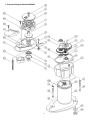
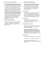
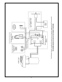
simpson-lawrence
sprint
400 WINDLASS
operation & maintenance instructions
○
1.
2.
3.
4.
5.
6.
○
○
○
○
○
○
○
○
○
○
○
○
○
○
○
○
○
Exploded Diagram
Planning the Installation
Accessories
Specification
Installation
Operating Instructions
○
○
○
○
○
○
○
○
○
○
○
○
○
○
○
○
○
○
○
○
○
○
○
○
○
○
7. Joining Rope to Chain
8. Maintenance
9. Dismantling Procedures
10. Troubleshooting
11. Warranty
This Manual forms part of the Product and MUST BE
RETAINED along with, OR incorporated into, the
Owner’s Manual for the vessel to which the Windlass
is fitted.
1
○
○
○
400
contents
1. Exploded Diagram Model #0060400
2
1. Parts List
Item
No.
List
Number
S-L USA
Part Number
1
2
3
4
6
7
8
9
10
11
12
13
14
15
16
17
18
19
20
35
36
38
39
40
41
42
43
44
45
46
47
65
66
67
68
69
70
80
81
206
60529G6
605-002
605-003
605-004
605-006
605-007
605-008
6060509
6060510
605-011
529-016
529-015
605-014
*
6044518
529-026
529-027
529-022
605-020
605-035
6060536
6060538
*
*
*
605-042
529-014
529-020
605-045
531-042
526-063
445-023
445-026
445-030
605-068
605-069
604-070
6060580
6065081
*
AA60529RC061E
AA6060502E
AA6060503E
AA6060504E
AA6060506E
AA6060507E
AA6060508E
AA6060509E
AA6060510E
AA6060511E
AA6052916E
AA6052915E
AA6060514E
AA6044518E
AA6052926E
AA6052927E
AA6052922E
AA6060520E
AA6060535E
AA6060536E
AA6060538E
AA6060542E
AA6052914E
AA6052920E
AA6060545E
AA6053142E
AA6052663E
AA6044523E
AA6044526E
AA6044530E
AA6060568E
AA6060569E
AA6060470E
AA6060580E
AA6065081E
Description
6 Pocket Rope/Chain Gipsy
Baseplate
Baseplate Cover
Mainshaft
Gipsy Drive Cap
Mainshaft Gear
Mainshaft Spacer
Torsion Spring
Control Arm
Control Arm Shoulder Screw
Ball Bearing
Needle Roller Clutch
Needle Roller Bearing
Seal
Drive Roller
Internal Circlip
External Circlip
Counter Sunk Socket Screw
Cheese Head Screw
Gear Case
1st Compound Gear
Compound Gear Assembly
12v Electric Motor
Motor Cover
Gasket
Needle Roller Bearing
Needle Roller Bearing
Counter Sunk Socket Screw
Socket Head Cap Screw
Socket Head Cap Screw
Lock Washer
Mounting Studs
Nut
Washer
Clamping Plate
Chain Pipe Sleeve
Nameplate
Rope/Chain Fleming
Chain Only Fleming
Cable Tie
Qty.
1
1
1
1
1
1
1
1
1
1
1
1
2
1
5
1
1
1
3
1
1
1
1
1
1
1
1
3
1
2
3
3
3
3
1
1
1
1
1
2
* Forms part of a kit listed below
List Number
S-L USA Part Number
6060590
6060591
6060592
6060594
6060595
AA6060590E
AA6060591E
AA6060592E
AA6060593E
AA6060595E
Description
Seal and Gasket Kit (Item # 15 and 14)
Above Deck Unit
Below Deck Unit
Motor Cover Kit (Item # 40 and 206)
Motor and Cable Tie Kit (Item # 39, 40 and 206)
3
WELCOME
Congratulations on becoming a proud owner of a Simpson-Lawrence Windlass. You can take
confidence in being among men and women who have depended on our products for over 90 years.
Simpson-Lawrence is known throughout the World as Manufacturers of Quality Marine Equipment. Our
factory manufactured anchoring components, anchor rodes, bow rollers and anchors, are specifically
engineered to compliment one another. To ensure that we serve you in the best manner possible, we
offer a complete range of anchoring systems to meet all of your needs.
For Your Safety
Read Before Installing and Operating Your Windlass
Classification Societies and Simpson-Lawrence require that a vessel at anchor must have its rode held by
a chain stopper or equivalent strong point at all times!
At all times it is the responsibility of the boat user to ensure that the anchor and rode are properly stowed
for the prevailing sea conditions. This is particularly important with high-speed powerboats, because an
anchor accidentally falling in the water while under way can cause considerable damage. An anchor
windlass is mounted in the most exposed position on a vessel and is thus subject to severe atmospheric
attack resulting in a possibility of corrosion in excess of that experienced with most other items of deck
equipment. As the windlass may only be used infrequently, the risk of corrosion is further increased. It is
essential that the windlass is regularly examined, operated and given any necessary maintenance.
*****
2. PLANNING the INSTALLATION
2.2 Package Contents
2.1 Gipsy Suitability
Windlass
Mounting Studs, Nuts, Washers and Clamping
Plate
Safety Instructions
Mounting Template
Instruction Booklet
Breaker/Isolator
Control Switch
The RC061 rope/chain gipsy is ideally suited
to our factory made anchor rodes, which
consist of rope spliced to a chain tail. Rope
used with this rope/chain gipsy must be
windlass grade, ½” (12-14mm) medium lay
three strand nylon. Ropes from different
manufacturers have wide variations in stretch
and consistency in diameter. Therefore, rope
and chain from other manufacturers may
require some experimentation to determine
the optimum size. On NO account should
multiplait ropes be used!
2.3 Additional Requirements
Each windlass installation requires:
WINDLASS INSTALLATION
¼” American ACCO BBB or ¼” American G-4
ISO (7mm) should be chosen to suit your
gipsy. Should you have difficulty in matching a
gipsy to your chain please consult your local
agent or our International Network of
Simpson-Lawrence distributors worldwide.
a. An approiate marine sealant
b. The following tools:
3/8” (10mm) Diameter Drill
2” (50mm) Diameter Hole Saw
½” (13mm) Wrench
File
Jig Saw or Trepanning Tool
4
3. ACCESSORIES
WIRING INSTALLATION
Flat Bladed Screwdriver
Crimping Pliers/Wire Stripper
Suitable electrical cable and crimp
Use only genuine Simpson-Lawrence parts and
accessories to ensure top performance and
eliminate the risk of voiding your warranty. For
additional accessories and replacement parts,
please see your dealer or call SimpsonLawrence.
terminals.
2.4 Electric Cable Selection
To achieve the best performance and
safeguard your electrical system it is essential
that any electrical windlass be fitted with
sufficiently large diameter cable to cope with
the current draw imposed upon it and to keep
the voltage drop within acceptable limits. In
any circumstance voltage drop due entirely to
cable resistance should not exceed 10% for a
12V installation.
25 Amp Breaker
HM25BKR(0050713)
Single Station
Reversing Control Switch
or
Multi Station Operation
Dual Direction Solenoid
0052519
0052531
The following table gives recommended cable
sizes. The recommendations are based on
total length of cable required, from the battery,
following the route of the cables.
With any of the following or the Switchgear
marketed by Simpson-Lawrence UK and its
International distributors throughout the world
can also be used.
Total length of cable run is from the battery
to the windlass, and from the windlass back
to the battery.
Hand Held Remote Switch
Black Covered Foot Switch
Black Covered Foot Switch
White Covered Foot Switch
White Covered Foot Switch
Remote Console Switch
DO NOT confuse cable Length with the
length of the vessel!
QU1002
QU900/D
QU900/U
QU900/D
QU900/U
HMCONSW
(0052518)
METRIC or STARTER CABLE
Cable Length
(ft./m)
51.0ft/15.5m
58.0ft/17.7m
72.0ft/21.6m
Size
(mm²)
4. SPECIFICATION
Performance
Maximum Load
Chain in Gipsy
Rope in Gipsy
6
7
8.5
AMERICAN CABLE
Cable Length
(ft.)
Size
(AWG)
44.0
73.0
10
8
In Multi Station installations 14 AWG wire
(1.5mm² cross sectional area, 21/0.30 PVC
covered) is used to connect the switches to the
reversing control box.
5
440 lbs. (200 kg)
450 lbs. (204 kg)
Typical Working Figures
LOAD
lbs./kg
SPEED
ft./min m/min
simply, by screwing two nuts onto the opposite
end. Put them close enough to one another to
use the inner one as a lock nut. Use the outer
nut to screw the nut into the case with the aid
of the spanner or wrench. Do this to each of
the nuts in turn and remove the nuts for later
use.
AMPS
55/25
110/50
220/100
330/150
70
60
46
25
21.3
18.3
14.0
7.6
17
35
54
72
Power Out
95
28.9
7
Apply a suitable sealant (Do not use 5200) to
the base of the windlass, any mount pad and
around the studs. DO NOT GET CAULK OR
SEALANT UNDER THE GEARTRAIN COVER
(ITEM # 3). Secure the windlass firmly to the
deck from below, using the nuts and washers
supplied.
Note: If using silicone or other rubbery type
sealant, it is advisable to allow curing of the
sealant before final tightening of the mounting
nuts.
5. INSTALLATION
5.1 Fitting the Windlass to the Deck
If the deck is not flat, a suitable mounting pad
may be required to take up camber or sheer.
Decks that are thin, or of foam or balsa
laminate construction, will require
reinforcement in order to spread the loads that
will be applied to the deck while the windlass is
in use. Place the windlass on the deck and
decide upon a position for it with reference to
the vessel’s stemhead roller and the chain
locker below. Rode lead from the roller should
ideally be fed horizontally back to the top of the
gipsy and along its centerline. There must be
sufficient vertical fall for the chain or rope, even
with a full locker, to draw the rode from the
gipsy when hauling in.
5.2 Wiring
The wiring system should be of the two cable
fully insulated return type, which avoids
possible electrolytic corrosion problems. We
recommend the use of type III stranded, tinned
copper wire with copper crimp terminals. Most
modern installations are negative return
(negative ground) but polarity should be
checked.
In a Multi Station installation, the reversing
control box must be sited in a dry location. Do
not install the control box in the anchor
locker. If a control box is installed in an anchor
locker it is exposed to harsh conditions it is not
designed to withstand. Furthermore this type of
installation will void your warranty.
The standard M8 threaded mounting studs
supplied suit deck and packing thickness of up
to 3 1/8” (76 mm). These are adequate for
most installations. Place the mounting
template on the deck or mounting pad in the
desired position for the windlass and hold it in
place using adhesive tape. Using a 3/8” (9.5
mm) diameter drill, make the three holes for
the mounting studs. With a 1 3/4” (44 mm)
diameter hole saw, make the hole for the rode
to pass through, then with a jig saw, remove
the rest of the material from the inside of the
inner thick line. To help avoid water absorption
by the deck, apply an appropriate marine
sealant to the freshly cut hole edges. When all
the holes have been made, remove the
template.
Overload protection must be built into the
windlass wiring circuit. This protects the wiring
and prevents undue damage to the windlass
motor, in the event of its being stalled by an
excessive load in service.
It is advisable to site the circuit breaker in a dry,
readily accessible place. Our recommended
Breaker/Isolator must be manually reset should
an overload occur that causes it to trip to the
‘OFF’ position.
Note: Crimp terminals should be used on all
wire ends wherever possible for good electrical
contacts.
Fully screw the three mounting studs into the
base of the windlass. This can be done, quite
6
6. OPERATING INSTRUCTIONS
5.3 Electromagnetic Compatability
As a prudent act of seamanship, anchor
recovery operations require the undivided
attention of skipper and crew to prevent
personal injury or damage to the vessel.
In a typical anchor recovery situation, the
windlass will pass through a number of
operational phases.
It is essential that this product does not cause
any electromagnetic disturbance to any other
electrical or electronic equipment installed in
the vessel. This will be achieved if the windlass
is connected to the same battery as the
vessel’s starter motor and not to the service
battery to which other equipment is connected.
In addition, the run of the wiring, from the
battery to the windlass, should be kept as far
apart from the other wiring on the vessel as
possible. For instance, if the main wiring loom
is to starboard, fit the windlass wiring to port. It
should be noted that there is no evidence to
indicate that windlass installations do cause
magnetic interference but the installer is
advised to carry out checks when the
installation is complete.
6.1 Safety First
To avoid personal injuries ensure that limbs,
fingers and clothing are kept clear of the
anchor rode and windlass during operation.
Always ensure that there are no swimmers or
divers nearby when dropping your anchor.
6.2 Letting Go
Release any independent anchor locks.
If it is safe to do so, let go under power by
operating a ‘Down’ control.
5.3 Control Switch Installation
Follow the mounting instructions supplied with
the switch. Remember, in a Multi Station
installation all switches must be wired in a
parallel circuit.
6.3 Lying to Anchor Safely
Vessels at anchor will snub on the rode and
this can cause slippage or apply excessive
loads to the windlass.
For maximum safety and to prevent
damage, the windlass must not be left to
take the entire force from the anchor rode
while at anchor. The rode should be made
fast directly to a bollard, sampson post or cleat.
6.4 Hauling In
Untie the bridle or replace the rode in the gipsy.
If it is safe to do so, operate an ‘Up’ control.
Having retrieved the anchor, ensure it is
independently secured to prevent its accidental
release.
7
6.5 Operating Tips
When anchoring, it is best to power the rode
out, allowing the vessel to take up stern way
before full scope is let out. This helps prevent
the rode from becoming tangled on top of your
anchor on the seabed.
To aid anchor recovery, we recommend that the
vessel’s engine be used to assist by moving the
vessel towards the anchor. We do not
recommend that the vessel be motored over
and beyond the anchor, as this can cause the
rode to damage your topsides.
As the anchor approaches the stemhead, the
last few feet of rode should be inched in by
judicious use of controls to avoid damage to
the vessel.
Having retrieved the anchor, ensure it is
independently secured to prevent accidental
release. It is strongly advised to use an anchor
safety strap (Part # HMSTRAP), or chain
stopper.
7. Joining Rope to Chain
When mooring stern to, at a suitable distance
from the jetty, deploy the anchor to prevent the
bow from swinging. Gently pay out the rode
under the influence of the stern way of the
vessel as it approaches the jetty. Make fast
your vessel with warps from the stern.
When splicing rope to chain, select a length of
chain that will avoid having the splice
positioned in the gipsy when the anchor comes
over the stemhead. Furthermore, ensure that
the splice is no tighter than the rope. A hard
splice is not desired.
With whipping twine or similar, seize your rope
8” from the rope’s end and unlay the strands.
Pass one strand through the chain link from
one side and the other two strands from the
opposite side.
Remove seizing and complete a back splice in
the normal manner for four full tucks.
With a hot knife pare down the three strands by
one half of thier diameter and continue with two
further tucks.
With a hot knife, carefully melt the ends back
into the line. Because of wide variations in
rope type and construction some
experimentation may be required.
Whip the line with permanent whipping at the
beginning of the taper.
The above method of joining is designed to
minimise chafe between the rope and chain but
8
as a matter of prudent seamanship the splice
should be checked regularly and remade if
there is any evidence of wear.
9.2 Control Arm Replacement
Remove Control Arm Shoulder Screw (Item #
11) to withdraw Control Arm (Item # 10). The
Torsion Spring (Item # 9) can easily be
withdrawn from within the Control Arm. To
replace Control Arm reverse above procedure.
8. MAINTENANCE
General Recommendations
Isolate the windlass electrically, before carrying
out any maintenance work.
9.3 Mainshaft Replacement & Lubrication
Service
Note: Lubrication and internal parts will not fall
out when the windlass is disassembled.
The geartrain and its bearings have been
lubricated for you with PFG 210 grease and
should require no regular attention. PFG is a
white synthetic grease containing PTFE. Use
grease of a similar specification throughout. It
is recommended that the above deck
components be stripped, cleaned and regreased at least annually. To do this, the gipsy
with its Fleming should be removed as
detailed above. Inspect the Mainshaft Seal
(Item #15) for signs of wear. If the seal is found
to be unserviceable, the Mainshaft will have to
be withdrawn and seal replaced. This entails
removing the Gear case (Item #35) and its
contents, using a 5mm Allen Wrench (Torque
Key). Holding the Motor (Item #39) remove the
Cap Screws (Item #45 and #46) and their Lock
Washers (Item # 47), the lower the below deck
assembly away. Remove the External Circlip
(snap ring (Item #18)) and withdraw the
Mainshaft Gear (Item #7). Take care to retain
the three Drive Rollers (Item #16) and the
Mainshaft Spacer (Part #8). The Mainshaft
can now be withdrawn above deck, with or
without the Gipsy Assembly attached,
provided the Fleming is no longer fixed to the
Baseplate. Remove the seal and replace it
with a new one. Clean the stripped down
components in kerosene, dry them and inpect
them for wear. Rebuild the windlass applying
generous amounts of grease. Do not forget to
grease around the Mainshaft Seal. Stick the
Drive Rollers to the Mainshaft with grease. To
reassemble, reverse the above procedure.
After the first two or three anchor recoveries,
check the mounting nuts to ensure that the
windlass is still fastened tightly to your deck, as
it should now be ‘bedded-in’.
Regularly wash down the exterior of your
windlass with fresh water.
Examine all electrical connections for possible
corrosion, clean and lightly grease as
necessary.
Anchor rode splice should be checked regularly
and remade if there is any evidence of wear.
The Gipsy (60526RC061) should be examined
on a regular basis basis, because it is a high
wear item. This Gipsy is designed for short
scopes of chain and will last longer if properly
used.
9. DISMANTLING PROCEDURES
9.1 Gipsy Replacement
Remove the Socket Screw (Item 3 19), using a
5mm A/F Torque Key. Withdraw the Gipsy
Drive Cap (Item # 6) and carefully set aside the
two Stainless Steel Rollers (Item # 16).
Remove the Screws (Item # 20) that retain the
Fleming (Item # 80) and the Baseplate Cover
(Item # 3) using a flat bladed screw driver. Pull
the Control Arm (Item # 10) outwards. Remove
the Gipsy assembly. Open the Fleming and
remove it from the gipsy. To replace a Gipsy,
reverse the above procedure but apply a drop
of Loctite to retain the Socket Screw (Item #
19) in the Mainshaft (Item # 4).
9
9.4 Electric Motor Replacement
10. TROUBLESHOOTING
Isolate the windlass electrically! Disconnect
the Motor Cables from the vessel’s wiring loom.
Remove the Gear Case (Item #35) using a
5mm Allen Wrench (Torque Key) as detailed
above. Remove the Compound Gears (Item
#36 & #38) to allow access to the three Motor
Mounting Screws (Item #44). Using a 3mm
Allen wrench, remove the screws. Part the
Motor from the Gear Case and cut through the
Cable Ties (Item #206), remove the Motor Boot
(Item #40 ). Ensure that there is a hole in the
bottom of the boot. Replace the Motor by
reversing the above procedure, using new
cable ties to retain the Motor Boot in position.
Use Loctite on the Motor Screws.
As with most electrical marine equipment the
majority of problems that arise are electrical in
nature. Therefore it is essential that the proper
voltage be maintained. The proper voltage on a
12 volt system is 13.5 volts. (Constant low
voltage will destroy the motor). Ensure that
electrical cable size is large enough to handle
the current draw imposed upon it and to keep
the voltage drop within acceptable limits. In any
circumstance voltage drop due entirely to cable
resistance should not exceed 10% for 12 volt
installation.
Follow the charts to trouble shoot the problem.
10
11
12
Failure to Operate
Troubleshooting Chart: H500 Reversing Control Switch (#0052519)
Is there voltage at the input terminal (positive)
to the control switch?
Yes ⇓
If no voltage is present the battery isolation
switch is off, the breaker is tripped or a fuse
has blown. The battery may also have be
dead or disconnected.
No ⇒
Check voltage at the output terminals of the
control switch with the switch on forward then
reverse.
Control switch is defective.
Is there voltage at either output terminal for
forward then reverse?
Yes ⇓
No ⇒
Replace the motor.
Sluggish Operation
Troubleshooting Chart
Ease the load and ensure the battery is well
charged.
Is the widlass overloaded?
Yes ⇓
No ⇒
There is a severe voltage drop in the circuit.
Check for undersized cables, poor
connections or corroded connections. Also
check for resistance across the battery
isolation switch or solenoid. (Feel them to
see if they are heating up).
Check the voltage across the motor leads with
the windlass on. (Proper voltage is 13.5 volts.
Constant low voltage will destroy the motor).
Is the voltage low? (Below 11.0 volts on a 12
volt system).
Yes ⇓
No ⇒
Is the voltage correct? (Above 11.0 volts and
anchor is not fouled).
The motor is defective. Replace the motor.
Yes ⇒
13
Multi-Station Installation
Troubleshooting Chart: Electric Windlass - Failure to Operate
Check the battery isolation switch, circuit
breaker, helm console switch and any fuses.
Is there voltage at the input terminals to the
solenoids and foot switches?
Yes ⇓
No ⇒
Press the foot switch or operate the remote
switch. Is there voltage at the positive switch
terminal on the solenoid?
Yes ⇓
The foot switch or remote switch (or its
wiring), is defective.
No ⇒
Check the solenoid coil ground circuit. If
okay, replace the solenoid.
Keep the foot or remote switch activated. Is
there voltage at the main output terminal on
the solenoid?
Yes ⇓
No ⇒
Check the voltage at the motor. If voltage is
present, the motor is defective. If you have
any questions call Simpson-Lawrence.
14
11. WARRANTY STATEMENT
WARRANTY COVERAGE:
Simpson-Lawrence, USA., warrants to the original purchaser, subject to the limitations and
exclusions described below, that this product will be free from defects, in material and
workmanship under normal use and service for a period of 1 year from the date of its original
sale. Simpson-Lawrence will repair or replace any part, which proves to be defective in normal
use during the period of the warranty.
WARRANTY CLAIMS PROCEDURES:
If a defect is discovered during the applicable warranty period, the buyer must promptly notify
Simpson-Lawrence of such, in writing, at the nearer address below, providing proof of purchase.
For warranty service, the product must be returned to Simpson-Lawrence for examination. This
examination will be performed at no charge to the buyer. The buyer is responsible for any labor
costs associated with preparing the product or parts for shipping or transporting the products or
parts to and from Simpson-Lawrence.
REMEDY:
Simpson-Lawrence will repair any defect in material or workmanship or, at its option, correct such
defect by replacing non-conforming goods or parts. Such repairs and/or new parts are warranted
for the unexpired portion of the original warranty, or for 90 days, whichever is later. Warranty work
(parts and/or labor) shall be at Simpson-Lawrence’s expense; however, product preparation and
shipping costs to and from Simpson-Lawrence shall be borne by the buyer. These remedies for
breach of warranty.
LIMITATIONS AND EXCLUSIONS:
(1) This warranty applies only if the product is used under non-commercial, normal use in
service, and shall not apply to (a) products subject to (i) conditions or usage that exceed the
products performance specifications, (ii) incorrect maintenance, or (iii) use in applications for
which they were not intended; (b) defects or damage caused by a force which exceed design
specifications, including but not limited to, wear and tear, corrosion or ultraviolet degradation;
and (c) defects or damages caused by unauthorized attachments, accessories or
modifications.
(2) Simpson Lawrence’s warranties of fitness and merchantability, as well as other expressed
warranties contained herein, shall apply only to those parts and components manufactured
and installed by Simpson Lawrence. Simpson Lawrence reserves the right to alter the
products specifications and design without prior notice.
THE FOREGOING WARRANTIES ARE EXCLUSIVE AND IN LIEU OF ALL OTHER
EXPRESSED WARRANTIES, IMPLIED WARRANTIES, INCLUDING BUT NOT LIMITED TO THE
IMPLIED WARRANTIESOF MERCHANTABILITY AND FITNESS FOR A PARTICULAR
PURPOSE, DO NOT EXTEND BEYOND THE DURATION OF THE EXPRESSED WARRANTIES
PROVIDED HEREIN.
IN NO CASE SHALL SIMPSON LAWRENCE BE LIABLE FOR ANY SPECIAL, INCIDENTAL OR
CONSEQUENTIAL DAMAGES BASED ON BREACH OF WARRANTY, BREACH OF CONTRACT,
NEGLIGENCE, STRICT TORT OR ANY OTHER LEGAL THEORY. THIS LIMITATION DOES NOT
APPLY TO CLAIMS FOR PERSONAL INJURY.
SOME STATES, OR COUNTRIES, DO NOT ALLOW THE EXCLUSION OR LIMITATION OF
INCIDENTAL OR CONSEQUENTIAL DAMAGES OR LIMITATIONS ON HOW LONG AN IMPLIED
WARRANTY LASTS, SO THE ABOVE LIMITATIONS OR EXCLUSIONS MAY NOT APPLY TO
YOU.
THIS WARRANTY GIVES YOU SPECIFIC LEGAL RIGHTS AND YOU MAY ALSO HAVE OTHER
RIGHTS WHICH VARY FROM STATE TO STATE, OR COUNTRY TO COUNTRY.
15
The models described in this document are subject to a policy of continual improvement. Simpson-Lawrence Engineering
Limited reserve the right to alter specifications and recommendations without notice. For the latest information regarding any
aspect of the windlass please contact your local agent or: -
Simpson-Lawrence Engineering Limited
Deanside Road
Hillington
GLASGOW
G52 4SZ
United Kingdom.
Customer Support
Simpson-Lawrence Limited
Telephone
Facsimile
:
:
+44 (0)141 304 8000
+44 (0)141 304 8001
Telephone
Facsimile
:
:
+44 (0)141 304 8025
+44 (0)141 304 8001
218/228 Edmiston Drive
Ibrox
GLASGOW
G51 2YT
United Kingdom.
Service Division
Telephone
Facsimile
Email
:
:
:
+44 (0)141 300 9100
+44 (0)141 427 5419
[email protected]
Telephone
:
:
:
+44 (0)141 300 9200
+44 (0)141 427 9666
+44 (0)141 427 5419
Facsimile
Simpson Lawrence USA Inc.
6208, 28th Street East
Bradenton
FLORIDA
34203-4123
United States of America.
Telephone
Facsimile
:
:
:
:
1 800 WINDLAS
(Toll Free) 1 800 946 3527
+1 941 753 7533
+1 941 746 7166
Copyright © Simpson-Lawrence Engineering Limited. All Rights Reserved. 0060400 (D1122-1)
16