1
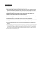
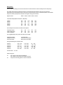
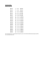
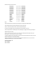
LEEDS PATTERN TRIGGER MODULE,
HYTEC TYPE 238
USER GUIDE AND OPERATIONAL NOTES
Issue 4.0 for issue 4 PCB Nov 2001.
Introduction
The purpose of this module is to detect patterns of adjacent 'hit' pulses from a hexagonal array of detectors,
essentially to eliminate the effect of random noise hits.
To achieve this, the module accepts 59 differential ECL inputs at the front panel, split internally into five overlapping
'patches' of 19 inputs each, and detects multiple adjacent pulsed logic states in each patch individually by a majority
logic comparator and a memory look-up [the comparator says "more than ‘n’ bits present", the memory look-up says
"interesting pattern", i.e. adjacent].
The inputs are connected by two front-panel 60-way IDC headers, 30 pairs on the upper connector and the
remaining 29 on the lower. One extra input is present, and is available as an alternative source for the Fast Clear
input, selected by wire link on the PCB.
Also on the front panel is a single-pole LEMO socket for a NIM l evel input to act as a Fast Clear signal.
On the rear panel is a position for a further IDC connector, providing scaling outputs for external logic and allowing
forcing inputs to be accepted to override decisions made by the majority logic. Other signals on this connector
provide a common VETO line, a Broadcast Clear/Enable line and an overall Trigger Output [for a readout controller].
The CAMAC port of this unit provides full access to all internal functions.
CAMAC Port
The function of the CAMAC port i s as follows:Command
F(0) A(0)
F(1) A(1)
F(1) A(12)
F(2) A(0)
F(16) A(0)
Purpose
Use of R/W lines
Read Patch memories at Pointer Address:R1-5 = Patch 1-5 'Q'
(Pointer incremented after operation)
Read Memory Address Pointer
R1-19
Read Patch Flag Status
R1-5 = Patch 1-5 Flag
Read Detected Trigger Pattern
R1-19 = Patch Data
R20-24 = Patch ID
Write Patch Memories at Pointer Address:W1-5 = Patch 1-5 'Data'
(Pointer incremented after operation)
Q, X notes
Q=’1 = valid
CAMAC Port, continued.
F(17) A(0)
Write Reference Setting
W1-5
F(17) A(1)
Write Memory Address Pointer
W1-19
F(24) A(0)
Disable Patch 1
None
F(24) A(1)
Disable Patch 2
None
F(24) A(2)
Disable Patch 3
None
F(24) A(3)
Disable Patch 4
None
F(24) A(4)
Disable Patch 5
None
F(25) A(15) Reset; Clear all Patch Flags, Disable all patches, clear Memory
Address Pointer.
F(26) A(0)
Enable Patch 1
None
F(26) A(1)
Enable Patch 2
None
F(26) A(2)
Enable Patch 3
None
F(26) A(3)
Enable Patch 4
None
F(26) A(4)
Enable Patch 5
None
F(26) A(15)
Global Enable - Permit Patch Flags to generate LAMs, 'ARM'.
Unaddressed Commands:- Z.S2 has the same effect as F(25) A(15).
Notes on CAMAC commands.
All commands produce the 'Command Accepted' response. X='1'.
F(2) A(0) produces a Q='1' response if the patch data being read is valid.
Comparator Reference operation:The comparator reference setting is applied to a 5-bit complementary binary DAC whose reference input is set at 1.2
volts. Thus each bit corresponds to 37.5 millivolts. Please note that the reference setting is no longer readable.
These values correspond to actual input majority as follows:Code Written
reference voltage (typical measured)
11111
11110
11101
11011
10111
01111
00000
0.015
0.053
0.091
0.173
0.325
0.632
1.190
Programming Procedure.
Command sequence:1)
Give the module a RESET command F(25) A(15) to ensure it is inactive.
2)
Now load up the patch memories by first writing the pointer to zero with F(17) A(1), then write consecutive
data to each location specifying 0/1 for each patch. The pointer auto-increments; bit W1 corresponds to
patch 1 and so on to W5; writing CAMAC '0' means ignore this patch pattern (address), '1' means store the
data if this pattern appears.
3)
4)
Write the comparator reference value with F(17) A(0) to select the number of bits required to trigger.
Enable each of the patches (to allow its flag to be set) with F(26) A(0-4).
5)
At this point, any input pulses will be captured if they satisfy the majority logic comparator and match a preloaded 'interesting' pattern.
6)
However, the module will not produce LAM or respond correctly to readout commands until......
7)
You issue a Global Enable command: F(26) A(15). This clears any pre-existing patch flags and enables the
LAM output.
8)
You should now wait for module LAM or use the rear-panel wired-OR trigger signal to start the readout
process.
9)
When this appears, read out the patch words stored with F(2) A(0). The first word you read will be the first to
be captured, identified by which of bits 20-24 are set [bit 20 corresponds to patch 1, bit 24 to patch 5]. The
next patch read out will be the highest 'priority' (numerical - based on patch number) now remaining, and
then the rest in descending sequence. When you get Q='0', that means you have had all the 'good' data.
10) To start capturing again, issue F(26) A(15).
Wiring Points:Issue 4 notes: The linking is now done on the PCB so no links need to be made. The delay lines are 5nS per tap
The output of the front-end comparator is used to clock the main latch and start the memory look-up process.
Subsequent logic uses delayed versions of this clock to decide whether to store or discard the pattern. The standard
delay line is 5nSec per tap and the outputs are brought to wiring pins as follows:Signal Function
Patch 1 Patch 2 Patch 3 Patch 4 Patch 5
Comparator Output (Main Latch Clock) delayed by:
1 Steps
2 Steps
3 Steps
4 Steps
5 Steps
P40
P10
P42
P12
P44
P46
P14
P48
P16
P50
P19
P3
P21
P5
P24
P63
P30
P65
P32
P68
P57
P26
P59
P28
P61
P51
P54
P53
P67
P22
P6
These delayed clocks need to be wired to three places:Comparator freeze
Clock Holding Latch
Clock Flag flip-flop
P37
P33
P8
P36
P35
P38
P17
P34
P52
The suggested delays are:- [these are linked on the board]
Comparator freeze:Holding Latch Clock:
FLAG Latch Clock:
10-15nS (2 step)
12nS minimum (3 steps)
25nS minimum (5 steps).
Giving the following wire-wrap link chart:PATCH 1:
PATCH 2:
PATCH 3:
PATCH 4:
PATCH 5:
P37 – P10;
P36 - P14;
P17 – P3;
P51 – P30;
P67 - P26;
P33 - P42;
P35 - P48;
P34 – P21;
P54 - P65;
P22 - P59;
and Fast Clear: P7 - P55.
Other wiring pins:P7:
P1
wire to P55 for Fast Clear from NIM input;
wire to P69 to use 'input 60' from the IDC connector.
Test point or free wiring point for common VETO line.
P8 - P44;
P38 – P50;
P52 - P24;
P53 - P68;
P6 - P61;
Connector Allocation.
60-way IDC:-(front view)
I/P 0 -ve
I/P 1 -ve
I/P 2 -ve
I/P 3 -ve
I/P 4 -ve
I/P 5 -ve
I/P 6 -ve
I/P 7 -ve
I/P 8 -ve
I/P 9 -ve
I/P 10 -ve
I/P 11 -ve
I/P 12 -ve
I/P 13 -ve
I/P 14 -ve
I/P 15 -ve
I/P 16 -ve
I/P 17 -ve
I/P 18 -ve
I/P 19 -ve
I/P 20 -ve
I/P 21 -ve
I/P 22 -ve
I/P 23 -ve
I/P 24 -ve
I/P 25 -ve
I/P 26 -ve
I/P 27 -ve
I/P 28 -ve
I/P 29 -ve
1
3
5
7
9
11
13
15
17
19
21
23
25
27
29
31
33
35
37
39
41
43
45
47
49
51
53
55
57
59
o
o
o
o
o
o
o
o
o
o
o
o
o
o
o
o
o
o
o
o
o
o
o
o
o
o
o
o
o
o
o
o
o
o
o
o
o
o
o
o
o
o
o
o
o
o
o
o
o
o
o
o
o
o
o
o
o
o
o
o
2
4
6
8
10
12
14
16
18
20
22
24
26
28
30
32
34
36
38
40
42
44
46
48
50
52
54
56
58
60
I/P 0 +ve
I/P 1 +ve
I/P 2 +ve
I/P 3 +ve
I/P 4 +ve
I/P 5 +ve
I/P 6 +ve
I/P 7 +ve
I/P 8 +ve
I/P 9 +ve
I/P 10 +ve
I/P 11 +ve
I/P 12 +ve
I/P 13 +ve
I/P 14 +ve
I/P 15 +ve
I/P 16 +ve
I/P 17 +ve
I/P 18 +ve
I/P 19 +ve
I/P 20 +ve
I/P 21 +ve
I/P 22 +ve
I/P 23 +ve
I/P 24 +ve
I/P 25 +ve
I/P 26 +ve
I/P 27 +ve
I/P 28 +ve
I/P 29 +ve
The second (lower) IDC connector starts with input 30 on pins 1 and 2 and ends with the spare input (59) on pins 59,
60. The orientation is the same.
Rear Panel 40-way Connector (rear view)
CK2 PATCH 1+
CK2 PATCH 2+
CK2 PATCH 3+
CK2 PATCH 4+
CK2 PATCH 5+
CK3 PATCH 1+
CK3 PATCH 2+
CK3 PATCH 3+
CK3 PATCH 4+
CK3 PATCH 5+
FORCE 1FORCE 2FORCE 3FORCE 4FORCE 5Global Enable
TRIGGER
SPARE-ECL
VETO
FLAGOUT
40
38
36
34
32
30
28
26
24
22
20
18
16
14
12
10
8
6
4
2
o
o
o
o
o
o
o
o
o
o
o
o
o
o
o
o
o
o
o
o
o
o
o
o
o
o
o
o
o
o
o
o
o
o
o
o
o
o
o
o
39
37
35
33
31
29
27
25
23
21
19
17
15
13
11
9
7
5
3
1
CK2 PATCH 1 CK2 PATCH 2 CK2 PATCH 3CK2 PATCH 4 CK2 PATCH 5 CK3 PATCH 1 CK3 PATCH 2 CK3 PATCH 3CK3 PATCH 4 CK3 PATCH 5 FORCE 1+
FORCE 2+
FORCE 3+
FORCE 4+
FORCE 5+
GROUND
GROUND
GROUND
GROUND
/FLAGOUT
Notes:CK2 is the main latch clock for each patch 'frozen' briefly by the comparator latch enable loop-back.
CK3 is the delayed main latch clock pulse ANDed with the memory output data.
PATCH 1+ refers to the positive sense ECL output for that patch related signal.
FLAGOUT is the propagation delay-corrected logical OR of all the patch flags, in ECL form.
VETO is a single-ended ECL wired-OR signal, which is pulled high by any trigger module seeing a patch flag true.
Suggested mating connector(s):Since the scaler outputs and forcing inputs, to say nothing of the overall Flag and VETO signals, need to go to
different places, a normal 40-way IDC connector is not suitable.
In order to fit multiple connectors in this position, we need to select a crimp-contact box-section socket, such as the
following example from the Farnell (Leeds) catalogue:Page 361: Berg 'Mini-Latch' crimp terminal housings and terminals available in two-row, 2+2, 5+5 and 10+10
configurations for picking up 2, 5 or 10 ECL pairs, for example.
P. Marshall, 1st October 1996.
Issue 2: August 1997.
Issue 3: Feb 2001.
Issue 4: Jan 2002.