1
HP ProLiant BL685c G6 Server Blade
User Guide
Part Number 508505-001
April 2009 (First Edition)
© Copyright 2009 Hewlett-Packard Development Company, L.P.
The information contained herein is subject to change without notice. The only warranties for HP products and services are set forth in the express
warranty statements accompanying such products and services. Nothing herein should be construed as constituting an additional warranty. HP
shall not be liable for technical or editorial errors or omissions contained herein.
Microsoft, Windows, and Windows Server are U.S. registered trademarks of Microsoft Corporation.
AMD Athlon is a trademark of Advanced Micro Devices, Inc.
Intended audience
This document is for the person who installs, administers, and troubleshoots servers and storage systems.
HP assumes you are qualified in the servicing of computer equipment and trained in recognizing hazards
in products with hazardous energy levels.
Contents
Component identification ............................................................................................................... 7
Front panel components ............................................................................................................................. 7
Front panel LEDs ....................................................................................................................................... 7
SAS and SATA hard drive LEDs................................................................................................................... 8
SAS and SATA hard drive LED combinations ................................................................................................ 9
System board components........................................................................................................................ 10
DIMM slots ................................................................................................................................... 11
Mezzanine connector definitions ..................................................................................................... 12
System maintenance switch............................................................................................................. 13
System maintenance switch procedures ............................................................................................ 13
HP c-Class Blade SUV Cable..................................................................................................................... 14
Operations................................................................................................................................. 15
Power up the server blade ........................................................................................................................ 15
Power down the server blade.................................................................................................................... 15
Remove the server blade .......................................................................................................................... 16
Remove the access panel.......................................................................................................................... 17
Install the access panel............................................................................................................................. 17
Remove the SAS hard drive ...................................................................................................................... 17
Remove the solid state drive...................................................................................................................... 17
Remove the DIMM baffle .......................................................................................................................... 18
Install the DIMM baffle ............................................................................................................................. 19
Setup......................................................................................................................................... 21
Overview ............................................................................................................................................... 21
Installing an HP BladeSystem c-Class enclosure ........................................................................................... 21
Preparing the enclosure .................................................................................................................. 21
Installing interconnect modules ........................................................................................................ 27
Connecting to the network .............................................................................................................. 28
Installing server blade options ................................................................................................................... 29
Installing a server blade ........................................................................................................................... 29
Completing the configuration .................................................................................................................... 30
Hardware options installation....................................................................................................... 31
Introduction ............................................................................................................................................ 31
Processor option...................................................................................................................................... 31
Memory option ....................................................................................................................................... 37
Advanced ECC memory configuration.............................................................................................. 37
DIMM installation guidelines ........................................................................................................... 38
DIMM population order.................................................................................................................. 38
Installing DIMMs ........................................................................................................................... 38
Solid state drive option ............................................................................................................................ 39
Mezzanine card option............................................................................................................................ 41
SAS controller option ............................................................................................................................... 43
Hot-plug SAS or SATA hard drive option .................................................................................................... 44
BBWC battery option............................................................................................................................... 46
HP Trusted Platform Module option ............................................................................................................ 48
Contents
3
Installing the Trusted Platform Module board ..................................................................................... 49
Retaining the recovery key/password .............................................................................................. 50
Enabling the Trusted Platform Module............................................................................................... 51
Cabling ..................................................................................................................................... 52
SSD cable routing ................................................................................................................................... 52
Cache module battery cabling .................................................................................................................. 52
Using the HP c-Class Blade SUV Cable ...................................................................................................... 53
Connecting locally to a server blade with video and USB devices.................................................................. 53
Accessing a server blade with local KVM ......................................................................................... 53
Accessing local media devices ........................................................................................................ 54
Software and configuration utilities ............................................................................................... 56
Server blade deployment tools .................................................................................................................. 56
RBSU requirement for Linux deployment............................................................................................ 56
Software drivers and additional components ..................................................................................... 56
HP BladeSystem c-Class Advanced management ............................................................................... 57
Network-based PXE deployment ...................................................................................................... 57
Deployment methods...................................................................................................................... 59
Configuration tools .................................................................................................................................. 62
SmartStart software........................................................................................................................ 62
HP ROM-Based Setup Utility............................................................................................................ 63
Array Configuration Utility .............................................................................................................. 64
Option ROM Configuration for Arrays ............................................................................................. 65
Re-entering the server serial number and product ID ........................................................................... 65
Management tools................................................................................................................................... 66
Automatic Server Recovery ............................................................................................................. 66
ROMPaq utility.............................................................................................................................. 66
iLO 2 Standard Blade Edition technology ......................................................................................... 66
Erase Utility .................................................................................................................................. 66
StorageWorks library and tape tools................................................................................................ 67
HP Systems Insight Manager ........................................................................................................... 67
Management Agents...................................................................................................................... 67
HP ProLiant Essentials Virtualization Management Software ................................................................ 67
HP ProLiant Essentials Vulnerability and Patch Management Pack ........................................................ 68
HP Insight Server Migration software for ProLiant ............................................................................... 68
HP ProLiant Essentials Performance Management Pack ....................................................................... 69
HP Insight Control Environment Suites............................................................................................... 69
HP Insight Control Linux Edition ....................................................................................................... 70
Redundant ROM support ................................................................................................................ 70
USB support and functionality ......................................................................................................... 70
Internal SD support ........................................................................................................................ 71
Diagnostic tools ...................................................................................................................................... 71
HP Insight Diagnostics .................................................................................................................... 71
HP Insight Diagnostics survey functionality ........................................................................................ 71
Integrated Management Log ........................................................................................................... 72
Array Diagnostic Utility .................................................................................................................. 72
Remote support and analysis tools ............................................................................................................. 72
HP Insight Remote Support software ................................................................................................. 72
Keeping the system current ....................................................................................................................... 73
Drivers ......................................................................................................................................... 73
ProLiant Support Packs ................................................................................................................... 73
Operating system version support .................................................................................................... 73
System Online ROM flash component utility ...................................................................................... 74
Contents
4
Change control and proactive notification ........................................................................................ 74
Care Pack .................................................................................................................................... 74
Troubleshooting .......................................................................................................................... 75
Troubleshooting resources ........................................................................................................................ 75
Pre-diagnostic steps ................................................................................................................................. 75
Important safety information............................................................................................................ 76
Symptom information ..................................................................................................................... 77
Prepare the server for diagnosis ...................................................................................................... 77
Service notifications................................................................................................................................. 78
Loose connections ................................................................................................................................... 78
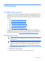
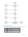
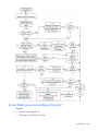
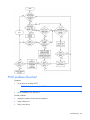
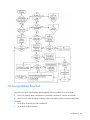
Troubleshooting flowcharts ....................................................................................................................... 78
Start diagnosis flowchart ................................................................................................................ 79
General diagnosis flowchart ........................................................................................................... 80
Server blade power-on problems flowchart ....................................................................................... 82
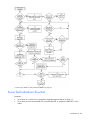
POST problems flowchart ............................................................................................................... 84
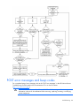
OS boot problems flowchart ........................................................................................................... 86
Server fault indications flowchart ..................................................................................................... 88
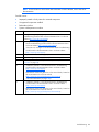
POST error messages and beep codes ....................................................................................................... 90
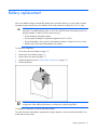
Battery replacement .................................................................................................................... 91
Regulatory compliance notices ..................................................................................................... 92
Regulatory compliance identification numbers ............................................................................................. 92
Federal Communications Commission notice............................................................................................... 92
FCC rating label............................................................................................................................ 92
Class A equipment......................................................................................................................... 92
Class B equipment ......................................................................................................................... 92
Declaration of conformity for products marked with the FCC logo, United States only....................................... 93
Modifications.......................................................................................................................................... 93
Cables ................................................................................................................................................... 93
Canadian notice (Avis Canadien).............................................................................................................. 94
European Union regulatory notice ............................................................................................................. 94
Disposal of waste equipment by users in private households in the European Union ......................................... 94
Japanese notice ...................................................................................................................................... 95
BSMI notice ............................................................................................................................................ 95
Korean notice ......................................................................................................................................... 95
Chinese notice ........................................................................................................................................ 96
Laser compliance .................................................................................................................................... 96
Battery replacement notice........................................................................................................................ 96
Taiwan battery recycling notice................................................................................................................. 97
Acoustics statement for Germany (Geräuschemission) .................................................................................. 97
Electrostatic discharge ................................................................................................................. 98
Preventing electrostatic discharge .............................................................................................................. 98
Grounding methods to prevent electrostatic discharge .................................................................................. 98
Specifications ............................................................................................................................. 99
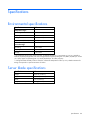
Environmental specifications ..................................................................................................................... 99
Server blade specifications ....................................................................................................................... 99
Technical support...................................................................................................................... 100
Before you contact HP............................................................................................................................ 100
HP contact information ........................................................................................................................... 100
Acronyms and abbreviations...................................................................................................... 101
Contents
5
Index....................................................................................................................................... 104
Contents
6
Component identification
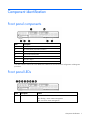
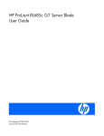
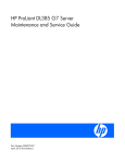
Front panel components
Item
Description
1
Serial label pull tab
2
HP c-Class Blade SUV Cable connector*
3
Power On/Standby button and LED
4
Server blade release button
5
Server blade release lever
6
Hard drive bay 2
7
Hard drive bay 1
* The SUV connector and the HP c-Class Blade SUV Cable are for some server blade configuration and diagnostic
procedures.
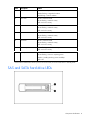
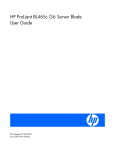
Front panel LEDs
Item
Description
Status
1
UID LED
Blue = Identified
Blue flashing = Active remote management
Off = No active remote management
Component identification 7
Item
Description
Status
2
Health LED
Green = Normal operation
Amber flashing = Degraded condition
Red flashing = Critical condition
3
Flex 1 LED
Green = Network linked
Green flashing = Network activity
Off = No link or activity
4
Flex 2 LED
Green = Network linked
Green flashing = Network activity
Off = No link or activity
5
Flex 3 LED
Green = Network linked
Green flashing = Network activity
Off = No link or activity
6
Flex 4 LED
Green = Network linked
Green flashing = Network activity
Off = No link or activity
7
SSD activity LED
Green flashing = Hard drive activity
Off = No link or activity
8
System power LED
Green = On
Green flashing = Server is requesting power
Amber = Standby (auxiliary power available)*
Off = Off
*If the Onboard Administrator denies power to the server blade, the server blade returns to Standby mode.
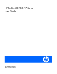
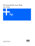
SAS and SATA hard drive LEDs
Component identification 8
Item
Description
1
Fault/UID LED (amber/blue)
2
Online LED (green)
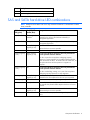
SAS and SATA hard drive LED combinations
NOTE: Predictive failure alerts can occur only when the hard drive is connected to a Smart
Array controller.
Online/activity
LED (green)
Fault/UID LED
(amber/blue)
Interpretation
On, off, or flashing Alternating amber
and blue
The drive has failed, or a predictive failure alert has been
received for this drive; it also has been selected by a
management application.
On, off, or flashing Steadily blue
The drive is operating normally, and it has been selected by a
management application.
On
Amber, flashing
regularly (1 Hz)
A predictive failure alert has been received for this drive.
On
Off
The drive is online, but it is not active currently.
Flashing regularly
(1 Hz)
Amber, flashing
regularly (1 Hz)
Do not remove the drive. Removing a drive may terminate the
current operation and cause data loss.
Replace the drive as soon as possible.
The drive is part of an array that is undergoing capacity
expansion or stripe migration, but a predictive failure alert has
been received for this drive. To minimize the risk of data loss, do
not replace the drive until the expansion or migration is
complete.
Flashing regularly
(1 Hz)
Off
Do not remove the drive. Removing a drive may terminate the
current operation and cause data loss.
The drive is rebuilding, erasing, or it is part of an array that is
undergoing capacity expansion or stripe migration.
Flashing irregularly Amber, flashing
regularly (1 Hz)
The drive is active, but a predictive failure alert has been
received for this drive. Replace the drive as soon as possible.
Flashing irregularly Off
The drive is active, and it is operating normally.
Off
Steadily amber
A critical fault condition has been identified for this drive, and
the controller has placed it offline. Replace the drive as soon as
possible.
Off
Amber, flashing
regularly (1 Hz)
A predictive failure alert has been received for this drive.
Replace the drive as soon as possible.
Off
Off
The drive is offline, a spare, or not configured as part of an
array.
Component identification 9
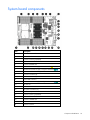
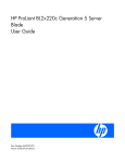
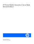
System board components
Item
Description
1
Processor 4 DIMM slots
2
Processor socket 4
3
Processor socket 2 (populated)
4
System maintenance switch
5
Processor 2 DIMM slots
6
Mezzanine connector 1 (Type I mezzanine only)
7
Mezzanine connector 2 (Type I or Type II mezzanine)
8
System board thumbscrews (3)
9
Enclosure connectors (2)
10
SSD data connectors (2)
11
Internal USB connector
12
Mezzanine connector 3 (Type I or Type II mezzanine)
13
SD card slot
14
TPM connector
15
SSD power connectors (2)
16
System battery
17
Processor socket 1 (populated)
18
SAS controller connector
19
Processor 1 DIMM slots
20
Processor 3 DIMM slots
21
Processor socket 3
Component identification 10
correspond to the symbols located on the interconnect bays. For more information, see the
The symbols
HP ProLiant BL685c G6 Server Blade Installation Instructions that ship with the server blade.
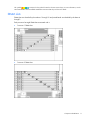
DIMM slots
DIMM slots are identified by the numbers 1 through 32 and paired banks are identified by the letters A
through P.
Each processor has eight DIMM slots associated with it:
•
Processor 1 DIMM slots
•
Processor 2 DIMM slots
Component identification 11
•
Processor 3 DIMM slots
•
Processor 4 DIMM slots
For installation guidelines and population order, see "Memory option (on page 37)."
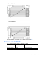
Mezzanine connector definitions
PCIe x8 mezzanine connectors support x16 cards at up to x8 speeds.
Item
Connector
Card support
Mezzanine connector 1
PCIe x8
Type I mezzanine card only
Mezzanine connector 2
PCIe x8
Type I or II mezzanine card
Mezzanine connector 3
PCIe x8
Type I or II mezzanine card
Component identification 12
System maintenance switch
Position
Function
Default
1*
iLO 2 security override
Off
2
Configuration lock
Off
3
Reserved
Off
4
Reserved
Off
5*
Password disabled
Off
6*
Reset configuration
Off
7
Reserved
Off
8
Reserved
Off
*To access redundant ROM, set S1, S5, and S6 to ON.
System maintenance switch procedures
When you perform troubleshooting steps, this guide may instruct you to perform the following procedures:
•
Clear the system configuration ("Clearing the system configuration" on page 13).
•
Access the redundant ROM ("Accessing the redundant ROM" on page 14).
To complete these procedures, you must change physical settings on the system maintenance switch.
Clearing the system configuration
RBSU can be used to restore the factory default configuration. For more information, see "HP ROM-Based
Setup Utility (on page 63)." If the system is unable to boot into RBSU, use the following steps to clear the
system configuration:
1.
Power down the server blade (on page 15).
2.
Remove the server blade (on page 16).
3.
Remove the access panel (on page 17).
4.
Change position 6 of the system maintenance switch to on.
5.
Install the access panel (on page 17).
6.
Install the server blade in the enclosure and power up the server blade.
7.
Wait for the POST message that prompts you to change the switch setting:
Maintenance switch detected in the "On" position.
Power off the server and turn switch to the "Off" position.
8.
Repeat steps 1 through 3.
9.
Change position 6 of the system maintenance switch to off.
10.
Repeat steps 5 and 6.
IMPORTANT: When the server blade boots after NVRAM is cleared, a delay of up to 2
minutes is normal. During this delay, the system appears non-functional. Do not attempt any
procedures during the delay.
Component identification 13
Accessing the redundant ROM
If the system ROM is corrupted, the system automatically switches to the redundant ROM in most cases. If
the system does not automatically switch to the redundant ROM, perform the following steps:
1.
Power down the server blade (on page 15).
2.
Remove the server blade (on page 16).
3.
Remove the access panel (on page 17).
4.
Change positions 1, 5, and 6 of the system maintenance switch to on.
5.
Install the access panel.
6.
Install the server blade in the enclosure and power up the server blade.
7.
After the system beeps, repeat steps 1 through 3.
8.
Change positions 1, 5, and 6 of system maintenance switch to off.
9.
Repeat steps 5 and 6.
If both the current and backup versions of the ROM are corrupt, return the system board for a service
replacement.
To switch to the backup ROM when the System ROM is not corrupt, use RBSU.
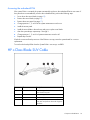
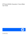
HP c-Class Blade SUV Cable
Item
Connector
Description
1
Server blade
For connecting to the SUV connector on the
server blade front panel
2
Video
For connecting a video monitor
3
USB
For connecting up to two USB devices
4
Serial
For trained personnel to connect a null modem
serial cable and perform advanced diagnostic
procedures
Component identification 14
Operations
Power up the server blade
The Onboard Administrator initiates an automatic power-up sequence when the server blade is installed.
If the default setting is changed, use one of the following methods to power up the server blade:
•
Use a virtual power button selection through iLO 2.
•
Press and release the Power On/Standby button.
When the server blade goes from the standby mode to the full power mode, the system power LED
changes from amber to green.
For more information about the Onboard Administrator, see the enclosure setup and installation guide on
the HP website (http://www.hp.com/support).
For more information about iLO 2, see "iLO 2 Standard Blade Edition technology (on page 66)."
Power down the server blade
Before powering down the server blade for any upgrade or maintenance procedures, perform a backup
of critical server data and programs.
Depending on the Onboard Administrator configuration, use one of the following methods to power down
the server blade:
•
Use a virtual power button selection through iLO 2.
This method initiates a controlled remote shutdown of applications and the OS before the server
blade enter standby mode.
•
Press and release the Power On/Standby button.
This method initiates a controlled shutdown of applications and the OS before the server blade enter
standby mode.
•
Press and hold the Power On/Standby button for more than 4 seconds to force the server blade to
enter standby mode.
This method forces the server blade to enter standby mode without properly exiting applications and
the OS. It provides an emergency shutdown method in the event of a hung application.
•
Execute one of the following commands using the Onboard Administrator CLI:
poweroff server all
or
poweroff server all force
The first command initiates a controlled shutdown of applications and the OS before the server blade
enter standby mode. The second form of the command forces the server blade to enter standby mode
without exiting applications and the OS. This is an emergency method to force a shutdown in the
event of a hung application.
Operations 15
•
Use the Onboard Administrator GUI to initiate a shutdown:
a. Select the Enclosure Information tab, then select the Overall checkbox in the Device Bays item.
b. Initiate a shutdown from the Virtual Power menu:
— Select Momentary Press to initiate a controlled shutdown of applications and the OS.
— Select Press and Hold to initiate an emergency shutdown of applications and the OS.
IMPORTANT: When the server blade are in standby mode, auxiliary power is still being
provided. To remove all power from the server blade, remove the server blade from the
enclosure.
After initiating a virtual power down command, be sure that the server blade go into standby mode by
observing that the system power LED is amber.
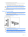
Remove the server blade
CAUTION: Do not use the server blade release lever to lift or carry the server blade. Always
support the weight of the server blade by handling the chassis directly. Improper use can
damage the release lever and the server blade.
1.
Identify the proper server blade ("Front panel LEDs" on page 7).
2.
Power down the server blade (on page 15).
3.
Remove the server blade.
4.
Place the server blade on a flat, level work surface.
WARNING: To reduce the risk of personal injury from hot surfaces, allow the drives and the
internal system components to cool before touching them.
CAUTION: To prevent damage to electrical components, properly ground the server blade
before beginning any installation procedure. Improper grounding can cause ESD.
Operations 16
Remove the access panel
To remove the component:
1.
Power down the server blade (on page 15).
2.
Remove the server blade (on page 16).
3.
Press the access panel release button, and then slide the access panel to the rear.
4.
Remove the access panel.
WARNING: To reduce the risk of personal injury from hot surfaces, allow the drives and the
internal system components to cool before touching them.
CAUTION: To prevent damage to electrical components, properly ground the server blade
before beginning any installation procedure. Improper grounding can cause ESD.
Install the access panel
1.
Place the access panel on top of the server blade. Allow the panel to extend past the rear of the
server blade approximately 1 cm (0.25 in).
2.
Slide the access panel to the closed position.
Remove the SAS hard drive
WARNING: To reduce the risk of personal injury from hot surfaces, allow the drives and the
internal system components to cool before touching them.
Remove the component as indicated.
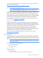
Remove the solid state drive
Operations 17
WARNING: To reduce the risk of personal injury from hot surfaces, allow the drives and the
internal system components to cool before touching them.
To remove the component:
1.
Power down the server blade (on page 15).
2.
Remove the server blade (on page 16).
3.
Remove the access panel (on page 17).
4.
Disconnect the SSD cables from the system board.
5.
Remove the SSD.
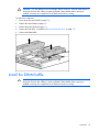
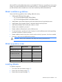
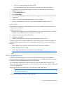
Remove the DIMM baffle
Operations 18
CAUTION: To avoid damage to the server blade and the enclosure, install all DIMM baffles in
the proper location after adding or replacing DIMMs. DIMM baffles that are missing or
installed incorrectly can compromise server blade and enclosure cooling.
To remove the component:
1.
Power down the server blade (on page 15).
2.
Remove the server blade (on page 16).
3.
Remove the access panel (on page 17).
4.
Remove the SSD drives, if installed ("Remove the solid state drive" on page 17).
5.
Remove the DIMM baffle.
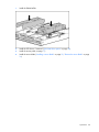
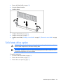
Install the DIMM baffle
CAUTION: To avoid damage to the server blade and the enclosure, install all DIMM baffles in
the proper location after adding or replacing DIMMs. DIMM baffles that are missing or
installed incorrectly can compromise server blade and enclosure cooling.
Operations 19
1.
Install the DIMM baffles.
2.
Install the SSD drives, if removed ("Solid state drive option" on page 39).
3.
Install the access panel (on page 17).
4.
Install the server blade ("Installing a server blade" on page 29, "Remove the server blade" on page
16).
Operations 20
Setup
Overview
Installation of a server blade requires the following steps:
1.
Install and configure an HP BladeSystem c-Class enclosure.
2.
Install any server blade options.
3.
Install interconnect modules in the enclosure.
4.
Connect the interconnect modules to the network.
5.
Install a server blade.
6.
Complete the server blade configuration.
Installing an HP BladeSystem c-Class enclosure
Before performing any server blade-specific procedures, install an HP BladeSystem c-Class enclosure.
The most current documentation for server blades and other HP BladeSystem components is available at
the HP website (http://www.hp.com/go/bladesystem/documentation).
Documentation is also available in the following locations:
•
Documentation CD that ships with the enclosure
•
HP Business Support Center website (http://www.hp.com/support)
•
HP Technical Documentation website (http://docs.hp.com)
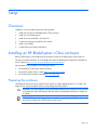
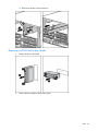
Preparing the enclosure
HP BladeSystem enclosures ship with device bay dividers to support half-height devices. To install a fullheight device, remove the blanks and the corresponding device bay divider.
CAUTION: To prevent improper cooling and thermal damage, do not operate the server blade
or the enclosure unless all hard drive and device bays are populated with either a component
or a blank.
IMPORTANT: For optimal cooling and system performance, configure the c7000 enclosure with
ten fans and configure the c3000 enclosure with six fans.
Setup
21
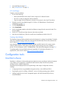
1.
Remove the device bay blank.
2.
Remove the three adjacent blanks.
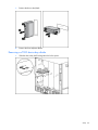
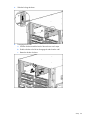
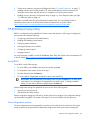
Removing a c7000 device bay divider
1.
Slide the device bay shelf locking tab to the left to open it.
Setup
22
2.
Push the device bay shelf back until it stops, lift the right side slightly to disengage the two tabs from
the divider wall, and then rotate the right edge downward (clockwise).
3.
Lift the left side of the device bay shelf to disengage the three tabs from the divider wall, and then
remove it from the enclosure.
Setup
23
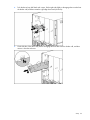
Removing a c3000 device bay mini-divider or device bay divider
1.
Slide the locking tab down.
2.
Remove the mini-divider or divider:
o
c3000 mini-divider:
Push the divider toward the back of the enclosure until the divider drops out of the chassis.
o
c3000 divider:
a. Push the divider toward the back of the enclosure until it stops.
b. Slide the divider to the left to disengage the tabs from the wall.
c.
Rotate the divider clockwise.
Setup
24
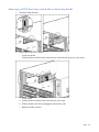
d. Remove the divider from the enclosure.
Removing a c3000 device bay divider
1.
Remove the device bay blank.
2.
Remove the three adjacent device bay blanks.
Setup
25
3.
Slide the locking tab down.
4.
Disengage the divider:
a. Push the divider toward the back of the enclosure until it stops.
b. Slide the divider to the left to disengage the tabs from the wall.
c.
Rotate the divider clockwise.
Setup
26
5.
Remove the divider from the enclosure.
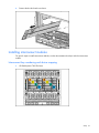
Installing interconnect modules
For specific steps to install interconnect modules, see the documentation that ships with the interconnect
module.
Interconnect bay numbering and device mapping
•
HP BladeSystem c7000 Enclosure
Setup
27
•
HP BladeSystem c3000 Enclosure
To support network connections for specific signals, install an interconnect module in the bay
corresponding to the embedded NIC or mezzanine signals.
Server blade signal
c7000 interconnect bay
c3000 interconnect bay
NIC 1 (Embedded)
1
1
NIC 2 (Embedded)
2
1
NIC 3 (Embedded)
1
1
NIC 4 (Embedded)
2
1
Mezzanine 1
3 and 4
2
Mezzanine 2
5 and 6
3 and 4
7 and 8
3 and 4
5 and 6
3 and 4
7 and 8
3 and 4
Mezzanine 3
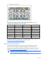
Interconnect bay labels
For detailed port mapping information, see the HP BladeSystem enclosure installation poster or the
HP BladeSystem enclosure setup and installation guide on the HP website
(http://www.hp.com/go/bladesystem/documentation).
Connecting to the network
To connect the HP BladeSystem to a network, each enclosure must be configured with network
interconnect devices to manage signals between the server blades and the external network.
Two types of interconnect modules are available for HP BladeSystem c-Class enclosures: Pass-Thru
modules and switch modules. For more information about interconnect module options, see the HP
website (http://www.hp.com/go/bladesystem/interconnects).
IMPORTANT: To connect to a network with a Pass-Thru module, always connect the Pass-Thru
module to a network device that supports Gigabit speed.
Setup
28
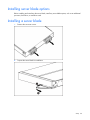
Installing server blade options
Before installing and initializing the server blade, install any server blade options, such as an additional
processor, hard drive, or mezzanine card.
Installing a server blade
1.
Remove the connector covers.
2.
Prepare the server blade for installation.
Setup
29
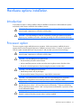
3.
Install the server blade.
Completing the configuration
To complete the server blade and HP BladeSystem configuration, see the overview card that ships with the
enclosure.
Setup
30
Hardware options installation
Introduction
If more than one option is being installed, read the installation instructions for all the hardware options
and identify similar steps to streamline the installation process.
WARNING: To reduce the risk of personal injury from hot surfaces, allow the drives and the
internal system components to cool before touching them.
CAUTION: To prevent damage to electrical components, properly ground the server before
beginning any installation procedure. Improper grounding can cause electrostatic discharge.
Processor option
The server supports single- and dual-processor operation. With two processors installed, the server
supports boot functions through the processor installed in processor socket 1. However, if processor 1
fails, the system automatically boots from processor 2 and provides a processor failure message.
WARNING: To reduce the risk of personal injury from hot surfaces, allow the drives and the
internal system components to cool before touching them.
CAUTION: To avoid damage to the system board:
• Do not touch the processor socket contacts.
• Always install the processor socket cover after removing the processor from the socket.
• Do not tilt or slide the processor when lowering the processor into the socket.
CAUTION: To avoid damage to the processor:
• Handle the processor only by the edges.
• Do not touch the bottom of the processor, especially the contact area.
CAUTION: To prevent possible server blade malfunction and damage to the equipment,
multiprocessor configurations must contain processors with the same part number.
CAUTION: The server blade supports only two- or four-processor configurations. Always
populate processor sockets 1 and 2 with processors and heatsinks. To prevent overheating,
always populate processor sockets 3 and 4 with processors and heatsinks or processor socket
covers and heatsink blanks.
CAUTION: The heatsink thermal interface media is not reusable and must be replaced if the
heatsink is removed from the processor after it has been installed.
Hardware options installation
31
IMPORTANT: Processor sockets 1 and 2 must always be populated. If either processor socket
is empty, the server blade does not power up.
To install a processor:
1.
Power down the server blade (on page 15).
2.
Remove the server blade (on page 16).
3.
Remove the access panel (on page 17).
4.
Remove the SAS hard drives ("Remove the SAS hard drive" on page 17), if installed.
5.
Remove the SAS controller, if installed.
6.
Remove the front bezel.
Hardware options installation
32
7.
Remove the heatsink blank. Retain the heatsink blank for future use.
CAUTION: The pins on the processor socket are very fragile. Any damage to them may
require replacing the system board.
8.
Remove the processor socket protective cover. Retain the cover for future use.
CAUTION: Failure to completely open the processor retaining latch prevents the processor
from seating during installation, leading to hardware damage.
Hardware options installation
33
9.
Open the processor retaining latch and the processor socket retaining bracket.
IMPORTANT: Be sure the processor remains inside the processor installation tool.
10.
If the processor has separated from the installation tool, carefully re-insert the processor in the tool.
11.
Align the processor installation tool with the socket and install the processor.
CAUTION: The processor is designed to fit one way into the socket. Use the alignment guides
on the processor and socket to properly align the processor with the socket.
Hardware options installation
34
12.
Press down firmly until the processor installation tool clicks and separates from the processor, and
then remove the processor installation tool.
Hardware options installation
35
13.
Close the processor retaining bracket and the processor retaining latch.
14.
Remove the thermal interface protective cover from the heatsink.
CAUTION: Heatsink retaining screws should be tightened in diagonally opposite pairs (in an
"X" pattern).
IMPORTANT: When installing the heatsink, align the guide pins on the processor retention
bracket with the alignment holes in the heatsink.
Hardware options installation
36
15.
Install the heatsink.
16.
Repeat these steps for the second processor and heatsink.
17.
Extend the serial label pull tab.
18.
Install the front bezel.
19.
Install the SAS controller, if removed.
20.
Install the SAS hard drives, if removed.
21.
Install the access panel (on page 17).
22.
Install the server blade ("Installing a server blade" on page 29, "Remove the server blade" on page
16).
Memory option
You can expand server memory by installing PC2-6400 Registered DDR2 SDRAM DIMMs or 8-GB PC25300 SDRAM DIMMs. The server supports up to 256 GB of memory using 32 8-GB DIMMs (eight DIMMs
per processor).
NOTE: The Advanced Memory Protection option in RBSU provides additional memory
protection beyond Advanced ECC. By default, the server is set to Advanced ECC Support. For
more information, refer to "HP ROM-Based Setup Utility (on page 63)."
For DIMM slot locations and bank assignments, see "DIMM slots (on page 11)."
Advanced ECC memory configuration
Advanced ECC memory is the default memory protection mode for this server blade. Standard ECC can
correct single-bit memory errors and detect multi-bit memory errors. When multi-bit errors are detected
using Standard ECC, the error is signaled to the server blade and causes the server blade to halt.
Advanced ECC protects the server blade against some multi-bit memory errors. Advanced ECC can
correct both single-bit memory errors and 4-bit memory errors if all failed bits are on the same DRAM
device on the DIMM.
Hardware options installation
37
Advanced ECC provides additional protection over Standard ECC because it is possible to correct certain
memory errors that would otherwise be uncorrected and result in a server blade failure. The server blade
provides notification that correctable error events have exceeded a pre-defined threshold rate.
DIMM installation guidelines
Observe the following guidelines when installing additional memory:
•
Install only the following memory types:
o
ECC PC2-6400 Registered DDR2 SDRAM DIMMs
o
ECC PC2-5300 Registered DDR2 8-GB SDRAM DIMMs
•
Install DIMMs in pairs (banks) beginning with banks farthest from each populated processor.
•
Install DIMMs with the greatest capacity in the banks farthest from the processor.
•
Install identical DIMMs with the same part number in a bank.
•
DIMMs must be installed for processor 1.
•
DIMMs installed in different banks can be of different sizes.
•
For best performance, populate one bank of memory for each installed processor before populating
more than one bank for a specific processor.
•
DIMMs installed in banks for processor 3 and 4 can be used only if processor 3 and 4 are installed.
•
Processors 3 and 4 can be installed without memory.
CAUTION: Always wear an antistatic wrist strap when working inside the server.
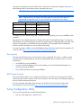
DIMM population order
Banks
Dual processor
Quad processor
1A, 2A and 9E, 10E
1st
1st
3B, 4B and 11F, 12F
2nd
3rd
5C, 6C and 13G, 14G
3rd
5th
7D, 8D and 15H, 16H
4th
7th
17I, 18I and 25M, 26M
—
2nd
19J, 20J and 27N, 28N
—
4th
21K, 22K and 29O, 30O
—
6th
23L, 24L and 31P, 32P
—
8th
Installing DIMMs
To install the component:
1.
Power down the server blade (on page 15).
2.
Remove the server blade (on page 16).
3.
Remove the access panel (on page 17).
Hardware options installation
38
4.
Remove the DIMM baffle (on page 18).
5.
Open the DIMM slot latches.
6.
Install the DIMM.
7.
Install the DIMM baffle (on page 19).
8.
Install the access panel (on page 17).
9.
Install the server blade ("Installing a server blade" on page 29, "Remove the server blade" on page
16).
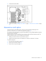
Solid state drive option
WARNING: To reduce the risk of personal injury from hot surfaces, allow the drives and the
internal system components to cool before touching them.
IMPORTANT: Installation of SATA SSD drives and hot-plug SAS drives at the same time is not
a supported configuration in this server blade.
To install the component:
1.
Power down the server blade (on page 15).
2.
Remove the server blade (on page 16).
3.
Remove the access panel (on page 17).
Hardware options installation
39
4.
Connect the cables to the SSD.
5.
Install the SSD.
Hardware options installation
40
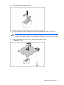
6.
Connect and route the cables.
7.
Install the access panel (on page 17).
8.
Install the server blade ("Installing a server blade" on page 29, "Remove the server blade" on page
16).
Mezzanine card option
Optional mezzanine cards enable network connectivity and provide Fibre Channel support. For
mezzanine card locations, see "System board components (on page 10)."
For mezzanine card signal mapping, see the HP ProLiant BL685c G6 Server Blade Installation Instructions
that ship with the server blade.
Optional mezzanine cards are classified as Type I mezzanine cards and Type II mezzanine cards. The
card type determines where it can be installed in the server blade:
•
Install Type I mezzanine cards on any mezzanine connector.
•
Install Type II mezzanine cards only on Mezzanine 2 connector or Mezzanine 3 connector.
To install the component:
1.
Power down the server blade (on page 15).
2.
Remove the server blade (on page 16).
3.
Remove the access panel (on page 17).
Hardware options installation
41
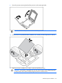
4.
Remove the mezzanine connector cover.
5.
Align the mezzanine connector on the option card with the mezzanine connector on the system
board.
CAUTION: To prevent damage to the server blade, apply pressure over the mezzanine
connector when installing the mezzanine card. Do not apply pressure to the edges of the card.
6.
Install the mezzanine card. Press down on the connector to seat the card:
o
Mezzanine 1 and 2
Hardware options installation
42
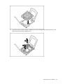
o
Mezzanine 3
7.
Install the access panel (on page 17).
8.
Install the server blade ("Installing a server blade" on page 29, "Remove the server blade" on page
16).
9.
Power up the server blade (on page 15).
SAS controller option
IMPORTANT: Installation of SATA SSD drives and hot-plug SAS drives at the same time is not
a supported configuration in this server blade.
To install the controller:
1.
Power down the server blade (on page 15).
2.
Remove the server blade (on page 16).
3.
Remove the access panel (on page 17).
Hardware options installation
43
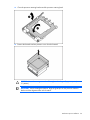
4.
Install the SAS controller.
5.
Install the access panel (on page 17).
6.
Remove hard drive blanks, as needed.
7.
Install the hot-plug SAS hard drives ("Hot-plug SAS or SATA hard drive option" on page 44).
8.
Install the server blade ("Installing a server blade" on page 29, "Remove the server blade" on page
16).
9.
Power up the server blade (on page 15).
Hot-plug SAS or SATA hard drive option
The server blade supports up to two hot-plug SAS or SATA drives. Installation of the SAS controller option
is also required.
CAUTION: To prevent improper cooling and thermal damage, do not operate the server blade
or the enclosure unless all hard drive and device bays are populated with either a component
or a blank.
IMPORTANT: Installation of SATA SSD drives and hot-plug SAS drives at the same time is not
a supported configuration in this server blade.
To install the component:
Hardware options installation
44
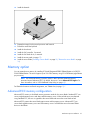
1.
Remove the hard drive blank.
2.
Prepare the hard drive.
Hardware options installation
45
3.
Install the hard drive.
4.
Determine the status of the hard drive from the hot-plug hard drive LEDs ("SAS and SATA hard drive
LEDs" on page 8).
5.
Resume normal server blade operations.
BBWC battery option
The battery pack option can be installed for a cache module located on the optional SAS controller
module or for a cache module installed on an optional mezzanine card controller.
CAUTION: To prevent a server blade malfunction or damage to the equipment, do not add or
remove the battery pack while an array capacity expansion, RAID level migration, or stripe
size migration is in progress.
CAUTION: After the server blade is powered down, wait 15 seconds and then check the
amber LED before removing the battery from the cache module. If the amber LED flashes after
15 seconds, do not remove the battery from the cache module. The cache module is backing
up data, and data is lost if the battery is detached before the LED is extinguished.
IMPORTANT: The battery pack might have a low charge when installed. In this case, a POST
error message is displayed when the server blade is powered up, indicating that the battery
pack is temporarily disabled. No action is necessary on your part. The internal circuitry
automatically recharges the batteries and enables the battery pack. This process might take up
to four hours. During this time, the cache module functions properly, but without the
performance advantage of the battery pack.
NOTE: The data protection and the time limit also apply if a power outage occurs. When
power is restored to the system, an initialization process writes the preserved data to the hard
drives.
To install the battery pack:
1.
Power down the server blade (on page 15).
Hardware options installation
46
2.
Remove the server blade (on page 16).
3.
Remove the access panel (on page 17).
4.
Connect the battery cable to the cache module.
5.
Connect the battery cable to the battery pack.
6.
Install the battery pack in the battery holder:
Hardware options installation
47
o
Hot-plug SAS controller option
o
Mezzanine card controller option
7.
Install the access panel (on page 17).
8.
Install the server blade ("Installing a server blade" on page 29, "Remove the server blade" on page
16).
9.
Power up the server blade (on page 15).
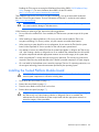
HP Trusted Platform Module option
Use these instructions to install and enable a TPM on a supported server blade. This procedure includes
three sections:
1.
Installing the Trusted Platform Module board (on page 49).
2.
Retaining the recovery key/password (on page 50).
3.
Enabling the Trusted Platform Module (on page 51).
Hardware options installation
48
Enabling the TPM requires accessing the ROM-Based Setup Utility (RBSU) ("HP ROM-Based Setup
Utility" on page 63). For more information about RBSU, see the HP website
(http://www.hp.com/support/smartstart/documentation).
TPM installation requires the use of drive encryption technology, such as the Microsoft® Windows®
BitLocker™ Drive Encryption feature. For more information on BitLocker™, see the Microsoft website
(http://www.microsoft.com).
CAUTION: Always observe the guidelines in this document. Failure to follow these guidelines
can cause hardware damage or halt data access.
When installing or replacing a TPM, observe the following guidelines:
•
Do not remove an installed TPM. Once installed, the TPM becomes a permanent part of the system
board.
•
When installing or replacing hardware, HP service providers cannot enable the TPM or the
encryption technology. For security reasons, only the customer can enable these features.
•
When returning a system board for service replacement, do not remove the TPM from the system
board. When requested, HP Service provides a TPM with the spare system board.
•
Any attempt to remove an installed TPM from the system board breaks or disfigures the TPM security
rivet. Upon locating a broken or disfigured rivet on an installed TPM, administrators should consider
the system compromised and take appropriate measures to ensure the integrity of the system data.
•
When using BitLocker™, always retain the recovery key/password. The recovery key/password is
required to enter Recovery Mode after BitLocker™ detects a possible compromise of system integrity.
•
HP is not liable for blocked data access caused by improper TPM use. For operating instructions, see
the encryption technology feature documentation provided by the operating system.
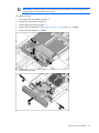
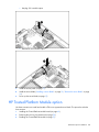
Installing the Trusted Platform Module board
WARNING: To reduce the risk of personal injury from hot surfaces, allow the drives and the
internal system components to cool before touching them.
1.
Power down the server blade (on page 15).
2.
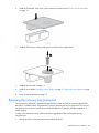
Remove the server blade (on page 16).
3.
Place the server blade on a flat, level work surface.
4.
Remove the access panel (on page 17).
CAUTION: Any attempt to remove an installed TPM from the system board breaks or disfigures
the TPM security rivet. Upon locating a broken or disfigured rivet on an installed TPM,
administrators should consider the system compromised and take appropriate measures to
ensure the integrity of the system data.
Hardware options installation
49
5.
Install the TPM board. Press down on the connector to seat the board ("System board components"
on page 10).
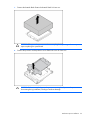
6.
Install the TPM security rivet by pressing the rivet firmly into the system board.
7.
Install the access panel (on page 17).
8.
Install the server blade ("Installing a server blade" on page 29, "Remove the server blade" on page
16).
9.
Power up the server blade (on page 15).
Retaining the recovery key/password
The recovery key/password is generated during BitLocker™ setup, and can be saved and printed after
BitLocker™ is enabled. When using BitLocker™, always retain the recovery key/password. The recovery
key/password is required to enter Recovery Mode after BitLocker™ detects a possible compromise of
system integrity.
To help ensure maximum security, observe the following guidelines when retaining the recovery
key/password:
•
Always store the recovery key/password in multiple locations.
Hardware options installation
50
•
Always store copies of the recovery key/password away from the server blade.
•
Do not save the recovery key/password on the encrypted hard drive.
Enabling the Trusted Platform Module
1.
When prompted during the start-up sequence, access RBSU by pressing the F9 key.
2.
From the Main Menu, select Server Security.
3.
From the Server Security Menu, select Trusted Platform Module.
4.
From the Trusted Platform Module Menu, select TPM Functionality.
5.
Select Enable, and then press the Enter key to modify the TPM Functionality setting.
6.
Press the Esc key to exit the current menu, or press the F10 key to exit RBSU.
7.
Reboot the server blade.
8.
Enable the TPM in the OS. For OS-specific instructions, see the OS documentation.
CAUTION: When a TPM is installed and enabled on the server blade, data access is locked if
you fail to follow the proper procedures for updating the system or option firmware, replacing
the system board, replacing a hard drive, or modifying OS application TPM settings.
For more information on firmware updates and hardware procedures, see the HP Trusted Platform Module
Best Practices White Paper on the HP website (http://www.hp.com/support).
For more information on adjusting TPM usage in BitLocker™, see the Microsoft website
(http://technet.microsoft.com/en-us/windowsvista/aa905065.aspx).
Hardware options installation
51
Cabling
SSD cable routing
Cache module battery cabling
Cabling 52
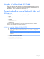
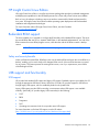
Using the HP c-Class Blade SUV Cable
The HP c-Class Blade SUV Cable enables the user to perform server blade administration, configuration,
and diagnostic procedures by connecting video and USB devices directly to the server blade. For SUV
cable connectors, see "HP c-Class Blade SUV Cable (on page 14)."
Connecting locally to a server blade with video and
USB devices
Use the SUV cable to connect a monitor and any of the following USB devices:
•
USB hub
•
USB keyboard
•
USB mouse
•
USB CD/DVD-ROM drive
•
USB diskette drive
Numerous configurations are possible. This section offers two possible configurations. For more
information, see "USB support and functionality (on page 70)."
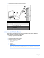
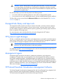
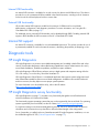
Accessing a server blade with local KVM
CAUTION: Before disconnecting the SUV cable from the connector, always squeeze the
release buttons on the sides of the connector. Failure to do so can result in damage to the
equipment.
NOTE: For this configuration, a USB hub is not necessary. To connect additional devices, use
a USB hub.
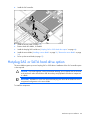
1.
Connect the SUV cable to the server blade.
2.
Connect the video connector to a monitor.
3.
Connect a USB mouse to one USB connector.
Cabling 53
4.
Connect a USB keyboard to the second USB connector.
Item
Description
1
Monitor
2
USB mouse
3
HP c-Class Blade SUV Cable
4
Video connector
5
Server blade
6
USB keyboard
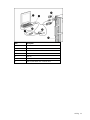
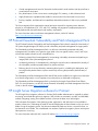
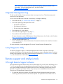
Accessing local media devices
Use the following configuration when configuring a server blade or loading software updates and
patches from a USB CD/DVD-ROM or a USB diskette.
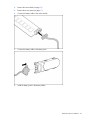
1.
Connect the SUV cable to the server blade.
2.
Connect the video connector to a monitor.
3.
Connect a USB hub to one USB connector.
4.
Connect the following to the USB hub:
o
USB CD/DVD-ROM drive
o
USB keyboard
o
USB mouse
o
USB diskette drive
NOTE: Use a USB hub when connecting a USB diskette drive and/or USB CD-ROM drive to
the server blade. The USB hub provides additional connections.
Cabling 54
Item
Description
1
Monitor
2
USB mouse
3
HP c-Class Blade SUV Cable
4
Server blade
5
USB hub
6
USB keyboard
7
USB CD/DVD-ROM drive or diskette drive
Cabling 55
Software and configuration utilities
Server blade deployment tools
RBSU requirement for Linux deployment
To properly install some versions of the Linux x64 operating system, the Linux x64 HPET Workaround
selection in RBSU must be enabled. If this step is not performed, a kernel panic can occur during boot.
The following operating systems are affected:
•
Red Hat Enterprise Linux 4 Update 3 x86_64
•
Red Hat Enterprise Linux 4 Update 4 x86_64
•
SUSE SLES9 SP3 x86_64
To avoid the kernel panic issue with these operating systems, perform the following steps:
1.
Access RBSU ("Using RBSU" on page 63).
2.
Select the Advanced Options menu.
3.
Set the Linux x64 HPET Workaround selection to Enabled.
4.
Save the changes and exit the utility.
HP is working with Linux providers to address this problem in future revisions of these operating systems.
This option may not be required with newer revisions of Red Hat Enterprise Linux or SUSE Linux Enterprise
Server.
Software drivers and additional components
HP offers the following additional software components for server blades:
•
Health and Wellness driver and IML viewer
•
iLO 2 Management interface driver
•
Rack infrastructure interface service
For Microsoft® Windows® OS users, these items are included in the HP ProLiant iLO 2 Standard Blade
Edition, available from the HP website (http://www.hp.com/servers/lights-out).
Linux OS users can download these components from the HP website
(http://www.hp.com/products/servers/linux).
For information on how to use these components with a Linux OS, see the HP website
(http://h18000.www1.hp.com/products/servers/linux/documentation.html).
Software and configuration utilities 56
HP BladeSystem c-Class Advanced management
iLO 2 is a standard component of ProLiant c-Class server blades that provides server health and remote
server blade manageability. Its features are accessed from a network client device using a supported web
browser. In addition to other features, iLO 2 provides keyboard, mouse, and video (text and graphics)
capability for a server blade, regardless of the state of the host OS or host server blade.
iLO 2 includes an intelligent microprocessor, secure memory, and a dedicated network interface. This
design makes iLO 2 independent of the host server blade and its OS. iLO 2 provides remote access to
any authorized network client, sends alerts, and provides other server blade management functions.
Using a supported web browser, you can:
•
Remotely access the console of the host server blade, including all text mode and graphics mode
screens with full keyboard and mouse controls.
•
Remotely power up, power down, or reboot the host server blade.
•
Remotely boot a host server blade to a virtual media image to perform a ROM upgrade or install an
OS.
•
Send alerts from iLO 2 regardless of the state of the host server blade.
•
Access advanced troubleshooting features provided by iLO 2.
•
Launch a web browser, use SNMP alerting, and diagnose the server blade with HP SIM.
•
Configure static IP bay settings for the dedicated iLO 2 management NICs on each server blade in
an enclosure for faster deployment.
To connect to the server blade using iLO 2, install the server blade in an enclosure. Onboard
Administrator assigns an IP address to enable iLO 2 connectivity to the server blade.
The c-Class tab enables you to control specific settings for the HP BladeSystem. iLO 2 also provides webbased status for the HP BladeSystem configuration.
For detailed information about iLO 2, refer to the HP Integrated Lights-Out User Guide on the HP website
(http://www.hp.com/servers/lights-out).
Network-based PXE deployment
PXE is a component of the Intel® WfM specification. The PXE model enables server blades to load and
execute an NBP from a PXE server and to execute a pre-configured image. The image can be an OS
image created by software utilities or a boot diskette image. This feature enables a user to configure a
server blade and install an OS over a network.
Deployment overview
When a PXE-enabled target server blade boots, it obtains an IP address from a DHCP server. The target
server blade obtains the name of the NBP from the appropriate boot server. Then, the target server blade
uses TFTP to download the NBP from the boot server and executes the image.
IMPORTANT: To connect to a network with a Pass-Thru module, always connect the Pass-Thru
module to a network device that supports Gigabit speed.
For each server blade being deployed, the PXE server must be connected to the NIC designated for PXE.
The server blade defaults PXE functions to NIC 1, but any of the NC series NICs in the server blade can
Software and configuration utilities 57
be designated for PXE in RBSU. For NIC connector locations, refer to the documentation included with the
server blade.
NOTE: Actual NIC numeration depends on several factors, including the OS installed on the
server blade.
To deploy an OS to multiple server blades, install a PXE deployment server on a network.
Deployment infrastructure
IMPORTANT: To connect to a network with a Pass-Thru module, always connect the Pass-Thru
module to a network device that supports Gigabit speed.
To establish a network-based PXE deployment infrastructure, provide the following software and minimum
hardware:
•
Client PC (administrative workstation)
o
AMD Athlon™ XP processor (700 MHz or greater recommended), AMD Athlon™ 64 processor,
or Intel® Pentium® III or higher processor (700 MHz or greater recommended)
o
128 MB of RAM
o
Microsoft® Windows® 2000 Professional or Microsoft® Windows® XP OS
o
Microsoft® Internet Explorer 5.5 or above with 128-bit encryption
o
Ethernet NIC with 10/100 RJ-45 connector
o
TCP/IP networking and an IP address compatible with one of the following: the iLO 2 Diagnostic
Port IP address or an assigned DHCP or static IP address
o
CD-ROM drive, CD/DVD-ROM drive, and/or diskette drive
o
Any of the following Java™ Runtime Environment versions:
1.3.1_02
1.3.1_07
1.3.1_08
1.4.1 for Windows® users only
1.4.2 for Linux users only
Access the Java™ Runtime Environment versions at the HP website
(http://java.sun.com/products/archive/index.html).
•
•
DHCP server (IP address assignment)
o
AMD Athlon™ XP processor (700 MHz or greater recommended), AMD Athlon™ 64 processor,
or Intel® Pentium® or Pentium® II 200-MHz or faster processor
o
64 MB of RAM
o
64 MB of free hard drive space
o
10-Mb/s network adapter
PXE deployment server (storing boot images)
o
AMD Athlon™ XP processor (700 MHz or greater recommended), AMD Athlon™ 64 processor,
or Intel® Pentium® III or higher processor (500 MHz recommended)
o
256 MB of RAM
Software and configuration utilities 58
•
o
10-Mb/s network adapter
o
CD-ROM drive
Windows® repository server (Windows® or Linux deployment)
o
Windows® 2000 or Windows Server® 2003 OS installed
o
Network connection
o
CD-ROM drive
o
1.5 GB of available disk space
o
TCP/IP networking and an IP address compatible with one of the following: the iLO 2 Diagnostic
Port IP address or an assigned DHCP or static IP address
o
CD-ROM drive and/or diskette drive
o
Any of the following Java™ Runtime Environment versions:
1.3.1_02
1.3.1_07
1.3.1_08
1.4.1 for Windows® users only
1.4.2 for Linux users only
Access the Java™ Runtime Environment versions at the HP website
(http://java.sun.com/products/archive/index.html).
•
Network server with an OS installed
Deployment methods
Three primary deployment methods are supported:
IMPORTANT: To deploy a server blade without the RDP, create a bootable diskette or image
of a bootable diskette.
•
PXE deployment (on page 59)
•
CD-ROM deployment (on page 60)
•
Diskette image deployment (on page 61)
PXE deployment
PXE enables server blades to load an image over the network from a PXE server, and then execute it in
memory. The first NIC on the server blade is the default PXE boot NIC, but any of the other NC series
NICs can be configured to boot PXE. For more information, refer to "Network-based PXE deployment (on
page 57)."
NOTE: Actual NIC numeration depends on several factors, including the OS installed on the
server blade.
HP recommends using one of the following methods for PXE deployment:
•
HP ProLiant Essentials RDP ("HP ProLiant Essentials Rapid Deployment Pack" on page 60)
•
SmartStart Scripting Toolkit (on page 60)
Software and configuration utilities 59
A number of third-party PXE deployment tools are available for Windows® and Linux. For additional
information, refer to the HP website
(ftp://ftp.compaq.com/pub/products/servers/management/pxe_wp.pdf).
HP ProLiant Essentials Rapid Deployment Pack
NOTE: To deploy server blades in an existing server blade enclosure, always use the most
recent version of RDP available at the HP website (http://www.hp.com/servers/rdp).
The RDP software is the preferred method for rapid, high-volume server deployments. The RDP software
integrates two powerful products: Altiris Deployment Solution and the HP ProLiant Integration Module.
The intuitive graphical user interface of the Altiris Deployment Solution console provides simplified pointand-click and drag-and-drop operations that enable you to deploy target servers, including server blades,
remotely. It enables you to perform imaging or scripting functions and maintain software images.
For more information about the RDP, refer to the HP ProLiant Essentials Rapid Deployment Pack CD or
refer to the HP website (http://www.hp.com/servers/rdp).
SmartStart Scripting Toolkit
The SmartStart Scripting Toolkit is a server deployment product that delivers an unattended automated
installation for high-volume server deployments. The SmartStart Scripting Toolkit is designed to support
ProLiant BL, ML, and DL servers. The toolkit includes a modular set of utilities and important documentation
that describes how to apply these new tools to build an automated server deployment process.
Using SmartStart technology, the Scripting Toolkit provides a flexible way to create standard server
configuration scripts. These scripts are used to automate many of the manual steps in the server
configuration process. This automated server configuration process cuts time from each server deployed,
making it possible to scale server deployments to high volumes in a rapid manner.
For more information, and to download the SmartStart Scripting Toolkit, refer to the HP website
(http://www.hp.com/servers/sstoolkit).
CD-ROM deployment
CD-ROM deployment involves using a bootable CD that executes scripts to configure the hardware and
install the OS. After the OS is configured, the server blade can access the network to locate the scripts
and files necessary for deployment. Before beginning the deployment process, connect the server blade to
the network.
NOTE: For more information about hardware and cabling configurations, see the documents
that ship with the enclosure.
Two methods are available for CD-ROM deployment:
•
iLO virtual CD-ROM (on page 60)
•
USB CD-ROM (on page 61)
iLO virtual CD-ROM
To deploy with a boot CD:
1.
Do one of the following:
o
Insert the boot CD into the client PC that is using the iLO 2 Remote Console.
Software and configuration utilities 60
o
Use iLO 2 to create an image file of the boot CD.
o
Copy the image of the boot CD to a location on the network or the client PC hard drive.
2.
Remotely access the server blade through iLO 2. Refer to "HP BladeSystem c-Class advanced
management (on page 57)."
3.
Click the Virtual Devices tab.
4.
Select Virtual Media.
5.
Use the Virtual Media applet to select the local CD or image file and connect the Virtual CD to the
server blade.
6.
Use the iLO 2 Virtual Power Button feature to reboot the server blade.
7.
After the server blade boots, follow the normal network installation procedure for the OS.
USB CD-ROM
This method uses SmartStart to facilitate loading the OS. However, SmartStart also allows for manual
loading of the OS and drivers.
To deploy with a boot CD:
1.
Use the local I/O cable to connect a USB CD-ROM drive to the server blade. Refer to "Connecting
locally to a server blade with video and USB devices (on page 53)."
2.
Insert the boot CD into the USB CD-ROM drive.
3.
Reboot the server blade.
4.
After the server blade boots, follow the normal installation procedure for an OS.
Windows Server® 2003 cannot be installed from a USB CD-ROM on the I/O cable if the hard drive is
completely blank (no partitions defined). To install Windows Server® 2003, use one of the following
methods:
•
Make a partition on the hard drive that Windows Server® 2003 will be loaded on.
•
Use the SmartStart CD 7.60 or later.
•
Use the Rapid Deployment Pack. For instructions, see the HP website
(http://h18013.www1.hp.com/products/servers/management/rdp.html?jumpid=reg_R1002_USE
N).
Diskette image deployment
To deploy with a diskette image, the user creates a DOS-based network-enabled boot diskette that
executes a script that configures the hardware and installs the OS. The diskette enables the server blade
to access the required deployment scripts and files on the network.
This method implies a deployment infrastructure that may include an administrator workstation, PXE
server, Microsoft® Windows® file share, or a Linux file share. For more information, refer to "Deployment
infrastructure (on page 58)."
Before beginning the deployment process, connect the server blade to the network.
NOTE: For more information about hardware and cabling configurations, see the documents
that ship with the enclosure.
Two methods are available for diskette image deployment:
Software and configuration utilities 61
•
iLO virtual floppy (on page 62)
•
PXE ("PXE deployment" on page 59)
iLO virtual floppy
To deploy with a boot diskette:
1.
Do one of the following:
o
Insert the boot diskette into the client PC that is using the iLO 2 Remote Console.
o
Use iLO 2 to create an image file of the boot diskette.
o
Copy the image of the boot diskette to a location on the network or the client PC hard drive.
2.
Remotely access the server blade through iLO 2. Refer to "HP BladeSystem c-Class advanced
management (on page 57)."
3.
Click the Virtual Devices tab.
4.
Select Virtual Media.
5.
Use the Virtual Media applet to select the local diskette or image file and connect the Virtual CD to
the server blade.
6.
Use the iLO 2 Virtual Power Button feature to reboot the server blade.
7.
After the server blade boots, follow the normal network installation procedure for the OS.
Creating a boot diskette
The SmartStart Scripting Toolkit provides the tools and information for creating a boot diskette. For details,
refer to the SmartStart Scripting Toolkit User Guide and download the latest version of the software from
the HP website (http://www.hp.com/servers/sstoolkit).
As an alternative method, configure the hardware manually with RBSU and the iLO 2 remote console.
With this method, the disk is more generic and integrates with an existing network OS installation
process. For more information, refer to "HP BladeSystem c-Class advanced management (on page 57)."
To operate properly, the server blade must have a supported OS. For the latest information on a
supported OS, refer to the HP website (http://www.hp.com/go/supportos).
Configuration tools
SmartStart software
SmartStart is a collection of software that optimizes single-server setup, providing a simple and consistent
way to deploy server configuration. SmartStart has been tested on many ProLiant server products,
resulting in proven, reliable configurations.
SmartStart assists the deployment process by performing a wide range of configuration activities,
including:
•
Configuring hardware using embedded configuration utilities, such as RBSU and ORCA
•
Preparing the system for installing "off-the-shelf" versions of leading operating system software
•
Installing optimized server drivers, management agents, and utilities automatically with every
assisted installation
Software and configuration utilities 62
•
Testing server hardware using the Insight Diagnostics Utility ("HP Insight Diagnostics" on page 71)
•
Installing software drivers directly from the CD. With systems that have internet connection, the
SmartStart Autorun Menu provides access to a complete list of ProLiant system software.
•
Enabling access to the Array Configuration Utility (on page 64), Array Diagnostic Utility (on page
72), and Erase Utility (on page 66)
SmartStart is included in the HP ProLiant Essentials Foundation Pack. For more information about
SmartStart software, refer to the HP ProLiant Essentials Foundation Pack or the HP website
(http://h18013.www1.hp.com/products/servers/management/smartstart/index.html).
HP ROM-Based Setup Utility
RBSU is a configuration utility embedded in ProLiant servers that performs a wide range of configuration
activities that can include the following:
•
Configuring system devices and installed options
•
Enabling and disabling system features
•
Displaying system information
•
Selecting the primary boot controller
•
Configuring memory options
•
Language selection
For more information on RBSU, see the HP ROM-Based Setup Utility User Guide on the Documentation CD
or the HP website (http://www.hp.com/support/smartstart/documentation).
Using RBSU
To use RBSU, use the following keys:
•
To access RBSU, press the F9 key during power-up when prompted.
•
To navigate the menu system, use the arrow keys.
•
To make selections, press the Enter key.
•
To access Help for a highlighted configuration option, press the F1 key.
IMPORTANT: RBSU automatically saves settings when you press the Enter key. The utility does
not prompt you for confirmation of settings before you exit the utility. To change a selected
setting, you must select a different setting and press the Enter key.
Default configuration settings are applied to the server at one of the following times:
•
Upon the first system power-up
•
After defaults have been restored
Default configuration settings are sufficient for proper typical server operation, but configuration settings
can be modified using RBSU. The system will prompt you for access to RBSU with each power-up.
Auto-configuration process
The auto-configuration process automatically runs when you boot the server for the first time. During the
power-up sequence, the system ROM automatically configures the entire system without needing any
Software and configuration utilities 63
intervention. During this process, the ORCA utility, in most cases, automatically configures the array to a
default setting based on the number of drives connected to the server.
NOTE: The server may not support all the following examples.
NOTE: If the boot drive is not empty or has been written to in the past, ORCA does not
automatically configure the array. You must run ORCA to configure the array settings.
Drives installed
Drives used
RAID level
1
1
RAID 0
2
2
RAID 1
3, 4, 5, or 6
3, 4, 5, or 6
RAID 5
More than 6
0
None
To change any ORCA default settings and override the auto-configuration process, press the F8 key when
prompted.
By default, the auto-configuration process configures the system for the English language. To change any
default settings in the auto-configuration process (such as the settings for language, operating system, and
primary boot controller), execute RBSU by pressing the F9 key when prompted. After the settings are
selected, exit RBSU and allow the server to reboot automatically.
For more information on RBSU, see the HP ROM-Based Setup Utility User Guide on the Documentation CD
or the HP website (http://www.hp.com/support/smartstart/documentation).
Boot options
Near the end of the boot process, the boot options screen is displayed. This screen is visible for several
seconds before the system attempts to boot from a supported boot device. During this time, you can do
the following:
•
Access RBSU by pressing the F9 key.
•
Access the System Maintenance Menu (which enables you to launch ROM-based Diagnostics or
Inspect) by pressing the F10 key.
•
Force a PXE Network boot by pressing the F12 key.
BIOS Serial Console
BIOS Serial Console allows you to configure the serial port to view POST error messages and run RBSU
remotely through a serial connection to the server COM port. The server that you are remotely configuring
does not require a keyboard and mouse.
For more information about BIOS Serial Console, see the BIOS Serial Console User Guide on the
Documentation CD or the HP website (http://www.hp.com/support/smartstart/documentation).
Array Configuration Utility
ACU is a browser-based utility with the following features:
•
Runs as a local application or remote service
Software and configuration utilities 64
•
Supports online array capacity expansion, logical drive extension, assignment of online spares, and
RAID or stripe size migration
•
Suggests the optimum configuration for an unconfigured system
•
Provides different operating modes, enabling faster configuration or greater control over the
configuration options
•
Remains available any time that the server is on
•
Displays on-screen tips for individual steps of a configuration procedure
For optimum performance, the minimum display settings are 800 × 600 resolution and 256 colors.
Servers running Microsoft® operating systems require Internet Explorer 5.5 (with Service Pack 1) or later.
For Linux servers, refer to the README.TXT file for additional browser and support information.
For more information, refer to the Configuring Arrays on HP Smart Array Controllers Reference Guide on
the Documentation CD or the HP website (http://www.hp.com).
Option ROM Configuration for Arrays
Before installing an operating system, you can use the ORCA utility to create the first logical drive, assign
RAID levels, and establish online spare configurations.
The utility also provides support for the following functions:
•
Reconfiguring one or more logical drives
•
Viewing the current logical drive configuration
•
Deleting a logical drive configuration
•
Setting the controller to be the boot controller
If you do not use the utility, ORCA will default to the standard configuration.
For more information regarding array controller configuration, refer to the controller user guide.
For more information regarding the default configurations that ORCA uses, refer to the HP ROM-Based
Setup Utility User Guide on the Documentation CD.
Re-entering the server serial number and product ID
After you replace the system board, you must re-enter the server serial number and the product ID.
1.
During the server startup sequence, press the F9 key to access RBSU.
2.
Select the System Options menu.
3.
Select Serial Number. The following warning is displayed:
WARNING! WARNING! WARNING! The serial number is loaded into the system
during the manufacturing process and should NOT be modified. This option
should only be used by qualified service personnel. This value should
always match the serial number sticker located on the chassis.
4.
Press the Enter key to clear the warning.
5.
Enter the serial number and press the Enter key.
6.
Select Product ID.
7.
Enter the product ID and press the Enter key.
8.
Press the Esc key to close the menu.
Software and configuration utilities 65
9.
Press the Esc key to exit RBSU.
10.
Press the F10 key to confirm exiting RBSU. The server will automatically reboot.
Management tools
Automatic Server Recovery
ASR is a feature that causes the system to restart when a catastrophic operating system error occurs, such
as a blue screen, ABEND, or panic. A system fail-safe timer, the ASR timer, starts when the System
Management driver, also known as the Health Driver, is loaded. When the operating system is
functioning properly, the system periodically resets the timer. However, when the operating system fails,
the timer expires and restarts the server.
ASR increases server availability by restarting the server within a specified time after a system hang or
shutdown. At the same time, the HP SIM console notifies you by sending a message to a designated
pager number that ASR has restarted the system. You can disable ASR from the HP SIM console or
through RBSU.
ROMPaq utility
The ROMPaq utility enables you to upgrade the system firmware (BIOS) or Lights-Out 100 firmware. To
upgrade the firmware, insert a ROMPaq diskette into the diskette drive or ROMPaq USB Key into an
available USB port and boot the system.
The ROMPaq utility checks the system and provides a choice (if more than one exists) of available
firmware revisions.
For more information about the ROMPaq utility, see the HP website (http://www.hp.com/go/support).
iLO 2 Standard Blade Edition technology
The iLO 2 subsystem is a standard component of selected ProLiant servers that provides server health and
remote server manageability. The iLO 2 subsystem includes an intelligent microprocessor, secure memory,
and a dedicated network interface. This design makes iLO 2 independent of the host server and its
operating system. The iLO 2 subsystem provides remote access to any authorized network client, sends
alerts, and provides other server management functions.
Using iLO 2, you can:
•
Remotely power up, power down, or reboot the host server.
•
Send alerts from iLO 2 regardless of the state of the host server.
•
Access advanced troubleshooting features through the iLO 2 interface.
•
Diagnose iLO 2 using HP SIM through a web browser and SNMP alerting.
For more information about iLO 2 features, refer to the iLO 2 documentation on the Documentation CD or
on the HP website (http://www.hp.com/servers/lights-out).
Erase Utility
Software and configuration utilities 66
CAUTION: Perform a backup before running the System Erase Utility. The utility sets the system
to its original factory state, deletes the current hardware configuration information, including
array setup and disk partitioning, and erases all connected hard drives completely. Refer to the
instructions for using this utility.
Run the Erase Utility if you must erase the system for the following reasons:
•
You want to install a new operating system on a server with an existing operating system.
•
You encounter an error when completing the steps of a factory-installed operating system installation.
The Erase Utility can be accessed from the Maintenance Utilities menu of the SmartStart CD ("SmartStart
software" on page 62).
StorageWorks library and tape tools
HP StorageWorks L&TT provides functionality for firmware downloads, verification of device operation,
maintenance procedures, failure analysis, corrective service actions, and some utility functions. It also
provides seamless integration with HP hardware support by generating and emailing support tickets that
deliver a snapshot of the storage system.
For more information, and to download the utility, refer to the StorageWorks L&TT website
(http://h18006.www1.hp.com/products/storageworks/ltt).
HP Systems Insight Manager
HP SIM is a web-based application that allows system administrators to accomplish normal administrative
tasks from any remote location, using a web browser. HP SIM provides device management capabilities
that consolidate and integrate management data from HP and third-party devices.
IMPORTANT: You must install and use HP SIM to benefit from the Pre-Failure Warranty for
processors, SAS and SATA hard drives, and memory modules.
For additional information, refer to the Management CD in the HP ProLiant Essentials Foundation Pack or
the HP SIM website (http://www.hp.com/go/hpsim).
Management Agents
Management Agents provide the information to enable fault, performance, and configuration
management. The agents allow easy manageability of the server through HP SIM software, and thirdparty SNMP management platforms. Management Agents are installed with every SmartStart assisted
installation or can be installed through the HP PSP. The Systems Management homepage provides status
and direct access to in-depth subsystem information by accessing data reported through the Management
Agents. For additional information, refer to the Management CD in the HP ProLiant Essentials Foundation
Pack or the HP website (http://www.hp.com/servers/manage).
HP ProLiant Essentials Virtualization Management Software
The ProLiant Essentials Virtual Machine Management Pack and ProLiant Essentials Server Migration Pack
plug-ins extend HP Systems Insight Manager capabilities to manage virtual machines.
The Virtual Machine Management Pack provides the following functionality:
Software and configuration utilities 67
•
Central management and control of VMware® and Microsoft® virtual machines with physical host to
virtual machine association
•
Easy identification of VMs or host servers reaching high CPU, memory, or disk utilization levels
•
Highly flexible move capabilities that enable live moves and moves to dissimilar host resources
•
Back up, template, and alternate host capabilities that enable restoration of VMs on any available
host
The Server Migration Pack automates the manual processes required for migrating servers between
physical or virtual platforms (P2V, V2P, and V2V), enabling easy migration to appropriate physical or
virtual platforms that meet performance and capacity requirements.
For more information about virtualization management software, see the HP website
(http://www.hp.com/go/vmmanage).
HP ProLiant Essentials Vulnerability and Patch Management Pack
The HP ProLiant Essentials Vulnerability and Patch Management Pack software extends the functionality of
HP Systems Insight Manager (HP SIM) to provide vulnerability and patch management for target systems.
The Vulnerability and Patch Management Pack is an all-in-one vulnerability assessment and patch
management tool. It enables you to gain the upper hand in the war against hackers, worms, and Trojan
software that exploit software security vulnerabilities by:
•
Enhancing system lifecycle management by incorporating vulnerability assessment and patching as
integral parts of the system management process.
•
Accelerating resolution of vulnerabilities by reducing the research time to understand the criticality of
the vulnerability and the expected behavior for patches and fixes.
•
Reducing the risk of security threats by automating the acquisition, scheduling the deployment, and
ensuring that the patches remain in place continuously enforcing the persistence (desired state) of
patches.
The Vulnerability and Patch Management Pack and HP SIM can be installed on a single server (referred to
as a shared configuration) or on a separate server (referred to as a distributed configuration).
The Vulnerability and Patch Management Pack is included on the Insight Control Data Center Edition
DVD. For more information, see the HP ProLiant Essentials Vulnerability and Patch Management Pack User
Guide, or the HP website (http://www.hp.com).
HP Insight Server Migration software for ProLiant
The HP Insight Server Migration software for ProLiant (SMP) enables administrators to upgrade or replace
an existing server blade through server migration. SMP provides an automated, accurate, and affordable
method of migrating existing server blades and their content to the latest server technologies.
SMP automates the migration of the operating system, applications, and data from one server blade to
another without errors, eliminating the need for manual redeployment of these elements on the new server
blade. During the migration process, the software automatically loads new drivers, required for boot, on
the destination server blade. The wizard-based user interface simplifies the migration process and requires
little experience or training.
For more information about the SMP, see the HP website (http://www.hp.com/go/migrate).
Software and configuration utilities 68
HP ProLiant Essentials Performance Management Pack
HP ProLiant Essentials Performance Management Pack (PMP) is an integrated performance management
solution that detects and analyzes hardware bottlenecks on HP ProLiant servers, select HP Integrity servers
and MSA500/MSA1000/MSA1500 shared storage devices.
PMP provides the tools you need to receive proactive notification of building bottlenecks, and debug
existing performance issues. PMP is automatically installed with HP Systems Insight Manager (HP SIM)
and is integrated with HP SIM. No software installation on the monitored servers is required, other than
the Insight Management Agents. PMP analyzes performance information to determine if there is a building
or existing restriction. You can display this information interactively, log the information to a database for
later analysis or reporting, and set up proactive notification using the HP Systems Insight Manager
notification mechanism.
For more information on HP ProLiant Essentials Performance Management Pack, see the documentation
available on the HP website (http://www.hp.com/products/pmp).
HP Insight Control Environment Suites
HP Insight Control Environment and Insight Control Environment for BladeSystem are integrated suites of
software that simplify the management of HP infrastructures.
The HP Insight Control Environment suites are licensing options for HP infrastructure management software
delivered on the Insight Control Management DVD. HP Insight Control Environment provides
comprehensive management for ProLiant ML/DL customers, while HP Insight Control Environment for
BladeSystem provides additional functionality for HP BladeSystem environments.
Using an integrated, wizard-based installer, Insight Control Environment suites install and configure HP
Systems Insight Manager (HP SIM) and HP ProLiant Essentials management software rapidly and
consistently. Once installed, Insight Control Environment suites deliver enhanced infrastructure stability by
improving control over IT assets, increasing responsiveness to business needs through flexible deployment
and optimization of compute resources, and providing tangible savings through improved IT staff
efficiency.
The software installed by Insight Control Environment suites delivers core management functionality for HP
ProLiant server and HP BladeSystem lifecycles, including:
•
Rapid server deployment
•
Health and performance monitoring
•
Comprehensive remote control
•
Vulnerability scanning and patch management
•
Power and thermal measurement, reporting, capping, and regulation
•
Integrated management of virtual and physical infrastructure
•
Third-party device management
For more information about Insight Control Environment suites, see the HP website
(http://www.hp.com/go/ice).
Software and configuration utilities 69
HP Insight Control Linux Edition
HP Insight Control Linux Edition is an all-in-one software package that provides Linux-based management
and deployment capabilities for the HP BladeSystem and its c-Class and p-Class ProLiant server blades.
Built on Linux, the software includes an easy-to-use interface customized for blades and optimized for
Linux users. HP Insight Control Linux Edition enables operating system deployment with both standard
installation and image-based technologies.
For more information about HP Insight Control Linux Edition, see the HP website
(http://www.hp.com/go/icle).
Redundant ROM support
The server enables you to upgrade or configure the ROM safely with redundant ROM support. The server
has a 4-MB ROM that acts as two, separate 2-MB ROMs. In the standard implementation, one side of the
ROM contains the current ROM program version, while the other side of the ROM contains a backup
version.
NOTE: The server ships with the same version programmed on each side of the ROM.
Safety and security benefits
When you flash the system ROM, ROMPaq writes over the backup ROM and saves the current ROM as a
backup, enabling you to switch easily to the alternate ROM version if the new ROM becomes corrupted
for any reason. This feature protects the existing ROM version, even if you experience a power failure
while flashing the ROM.
USB support and functionality
USB support
HP provides both standard USB support and legacy USB support. Standard support is provided by the OS
through the appropriate USB device drivers. Before the OS loads, HP provides support for USB devices
through legacy USB support, which is enabled by default in the system ROM.
Legacy USB support provides USB functionality in environments where USB support is not available
normally. Specifically, HP provides legacy USB functionality for the following:
•
POST
•
RBSU
•
Diagnostics
•
DOS
•
Operating environments which do not provide native USB support
For more information on ProLiant USB support, see the HP website
(http://h18004.www1.hp.com/products/servers/platforms/usb-support.html).
Software and configuration utilities 70
Internal USB functionality
An internal USB connector is available for use with security key devices and USB drive keys. This solution
provides for use of a permanent USB key installed in the internal connector, avoiding issues of clearance
on the front of the rack and physical access to secure data.
External USB functionality
HP provides external USB support to enable local connection of USB devices for server blade
administration, configuration, and diagnostic procedures. For more information, see "Using the HP cClass Blade SUV Cable (on page 53)."
For additional security, external USB functionality can be disabled through RBSU. Disabling external USB
support in RBSU disables the USB connectors on the HP c-Class Blade SUV Cable.
Internal SD support
An internal SD connector is available for use with embedded Hypervisors. This solution provides for use of
a permanently installed SD card in the internal connector, decreasing the possibility of tampering or loss.
Diagnostic tools
HP Insight Diagnostics
HP Insight Diagnostics is a proactive server blade management tool, available in both offline and online
versions, that provides diagnostics and troubleshooting capabilities to assist IT administrators who verify
server blade installations, troubleshoot problems, and perform repair validation.
HP Insight Diagnostics Offline Edition performs various in-depth system and component testing while the
OS is not running. To run this utility, launch the SmartStart CD.
HP Insight Diagnostics Online Edition is a web-based application that captures system configuration and
other related data needed for effective server blade management. Available in Microsoft® Windows®
and Linux versions, the utility helps to ensure proper system operation.
For more information or to download the utility, refer to the HP website
(http://www.hp.com/servers/diags).
HP Insight Diagnostics survey functionality
HP Insight Diagnostics (on page 71) provides survey functionality that gathers critical hardware and
software information on ProLiant server blades.
This functionality supports operating systems that may not be supported by the server blade. For operating
systems supported by the server blade, see the HP website (http://www.hp.com/go/supportos).
If a significant change occurs between data-gathering intervals, the survey function marks the previous
information and overwrites the survey data files to reflect the latest changes in the configuration.
Survey functionality is installed with every SmartStart-assisted HP Insight Diagnostics installation, or it can
be installed through the HP PSP ("ProLiant Support Packs" on page 73).
Software and configuration utilities 71
NOTE: The current version of SmartStart provides the memory spare part numbers for the
server blade. To download the latest version, see the HP website
(http://www.hp.com/support).
Integrated Management Log
The IML records hundreds of events and stores them in an easy-to-view form. The IML timestamps each
event with 1-minute granularity.
You can view recorded events in the IML in several ways, including the following:
•
From within HP SIM ("HP Systems Insight Manager" on page 67)
•
From within operating system-specific IML viewers:
o
For NetWare: IML Viewer
o
For Windows®: IML Viewer
o
For Linux: IML Viewer Application
•
From within the iLO 2 user interface
•
From within HP Insight Diagnostics (on page 71)
•
From within the Onboard Administrator GUI
For more information, see the HP BladeSystem Onboard Administrator User Guide on the HP website
(http://www.hp.com/go/bladesystem/documentation).
•
From the Onboard Administrator CLI
See the HP BladeSystem Onboard Administrator Command Line Interface User Guide for information
on accessing the CLI.
For more information, see the Management CD in the HP ProLiant Essentials Foundation Pack.
Array Diagnostic Utility
The HP Array Diagnostics Utility is a web-based application that creates a report of all HP storage
controllers and disk drives. This report provides vital information to assist in identifying faults or conditions
that may require attention. ADU can be accessed from the SmartStart CD ("SmartStart software" on page
62) or downloaded from the HP website (http://www.hp.com).
Remote support and analysis tools
HP Insight Remote Support software
HP Insight Remote Support software delivers secure remote support for your HP Servers and Storage, 24 X
7, so you can spend less time solving problems and more time focused on your business. You can have
your systems remotely monitored for hardware failure using secure technology that has been proven at
thousands of companies around the world. In many cases, you can avoid problems before they occur.
There are two HP Insight Remote Support solutions:
•
For small and midsize environments: HP Insight Remote Support Standard provides basic remote
monitoring, notification/advisories and service dispatch. It is optimized for environments with 1 to
Software and configuration utilities 72
50 servers and can be installed on a shared HP ProLiant Windows application server. The software
supports HP EVA storage devices, HP ProLiant, BladeSystems, HP Integrity and HP 9000 servers
running Microsoft Windows, Red Hat Enterprise Linux, Novell SUSE and Novell Netware. Download
from the HP website
(http://h20392.www2.hp.com/portal/swdepot/displayProductInfo.do?productNumber=RSSWMBA
SE).
•
For midsize and large environments: HP Insight Remote Support Pack (formerly Service Essentials
Remote Support Pack) is targeted for larger environments and is integrated with HP Systems Insight
Manager (SIM). It provides comprehensive remote monitoring, notification/advisories, dispatch and
proactive service support for nearly all HP servers, storage, network and SAN environments, plus
selected Dell and IBM Windows servers that have a support obligation with HP. It also enables HP to
deliver higher levels of proactive support in line with HP Mission Critical Services support
agreements. Download from the HP website
(http://h20392.www2.hp.com/portal/swdepot/displayProductInfo.do?productNumber=ISDVD).
Both HP Insight Remote Support solutions are available at no additional cost to customers with a valid
warranty on HP technology, an HP Care Pack Service or HP contractual support agreement.
For more information, visit the HP website (http://www.hp.com/go/insightremotesupport)
Keeping the system current
Drivers
IMPORTANT: Always perform a backup before installing or updating device drivers.
The server includes new hardware that may not have driver support on all OS installation media.
If you are installing a SmartStart-supported OS, use the SmartStart software (on page 62) and its Assisted
Path feature to install the OS and latest driver support.
If you are installing drivers from the SmartStart CD, be sure that you are using the latest SmartStart version
that your server blade supports. To verify that your server blade is using the latest supported version, see
the HP website (http://www.hp.com/support). For more information, see the documentation provided
with the SmartStart CD.
If you do not use the SmartStart CD to install an OS, drivers for some of the new hardware are required.
These drivers, as well as other option drivers, ROM images, and value-add software can be downloaded
from the HP website (http://www.hp.com/support).
ProLiant Support Packs
PSPs represent operating system-specific bundles of ProLiant optimized drivers, utilities, and management
agents. Refer to the PSP website
(http://h18000.www1.hp.com/products/servers/management/psp.html).
Operating system version support
Refer to the operating system support matrix (http://www.hp.com/go/supportos).
Software and configuration utilities 73
System Online ROM flash component utility
The Online ROM Flash Component Utility enables system administrators to efficiently upgrade system or
controller ROM images across a wide range of servers and array controllers. This tool has the following
features:
•
Works offline and online
•
Supports Microsoft® Windows Server™ 2003 and Linux operating systems
IMPORTANT: This utility supports operating systems that may not be supported by the server.
For operating systems supported by the server, see the HP website
(http://www.hp.com/support).
•
Integrates with other software maintenance, deployment, and operating system tools
•
Automatically checks for hardware, firmware, and operating system dependencies, and installs only
the correct ROM upgrades required by each target server
To download the tool and for more information, see the HP website
(http://h18000.www1.hp.com/support/files/index.html).
Change control and proactive notification
HP offers Change Control and Proactive Notification to notify customers 30 to 60 days in advance of
upcoming hardware and software changes on HP commercial products.
For more information, refer to the HP website (http://www.hp.com/go/pcn).
Care Pack
HP Care Pack Services offer upgraded service levels to extend and expand standard product warranty
with easy-to-buy, easy-to-use support packages that help you make the most of your server investments.
Refer to the Care Pack website (http://www.hp.com/hps/carepack/servers/cp_proliant.html).
Software and configuration utilities 74
Troubleshooting
Troubleshooting resources
The HP ProLiant Servers Troubleshooting Guide provides procedures for resolving common problems and
comprehensive courses of action for fault isolation and identification, error message interpretation, issue
resolution, and software maintenance on ProLiant servers and server blades. This guide includes problemspecific flowcharts to help you navigate complex troubleshooting processes. To view the guide, select a
language:
•
English (http://www.hp.com/support/ProLiant_TSG_en)
•
French (http://www.hp.com/support/ProLiant_TSG_fr)
•
Italian (http://www.hp.com/support/ProLiant_TSG_it)
•
Spanish (http://www.hp.com/support/ProLiant_TSG_sp)
•
German (http://www.hp.com/support/ProLiant_TSG_gr)
•
Dutch (http://www.hp.com/support/ProLiant_TSG_nl)
•
Japanese (http://www.hp.com/support/ProLiant_TSG_jp)
The HP BladeSystem c-Class Enclosure Troubleshooting Guide provides procedures and solutions for
troubleshooting HP BladeSystem c-Class enclosures. This guide explains how to use the Insight Display to
troubleshoot enclosures, and it includes a flowchart to help you navigate the troubleshooting process. To
view the guide, see the HP website (http://www.hp.com/support/BladeSystem_Enclosure_TSG_en).
Pre-diagnostic steps
WARNING: To avoid potential problems, ALWAYS read the warnings and cautionary
information in the server documentation before removing, replacing, reseating, or modifying
system components.
IMPORTANT: This guide provides information for multiple servers. Some information may not
apply to the server you are troubleshooting. Refer to the server documentation for information
on procedures, hardware options, software tools, and operating systems supported by the
server.
1.
Review the important safety information (on page 76).
2.
Gather symptom information (on page 77).
3.
Prepare the server for diagnosis (on page 77).
4.
Use the Start diagnosis flowchart (on page 79) to begin the diagnostic process.
Troubleshooting 75
Important safety information
Familiarize yourself with the safety information in the following sections before troubleshooting the server.
Important safety information
Before servicing this product, read the Important Safety Information document provided with the server.
Symbols on equipment
The following symbols may be placed on equipment to indicate the presence of potentially hazardous
conditions.
This symbol indicates the presence of hazardous energy circuits or electric shock
hazards. Refer all servicing to qualified personnel.
WARNING: To reduce the risk of injury from electric shock hazards, do not open this
enclosure. Refer all maintenance, upgrades, and servicing to qualified personnel.
This symbol indicates the presence of electric shock hazards. The area contains no
user or field serviceable parts. Do not open for any reason.
WARNING: To reduce the risk of injury from electric shock hazards, do not open this
enclosure.
This symbol on an RJ-45 receptacle indicates a network interface connection.
WARNING: To reduce the risk of electric shock, fire, or damage to the equipment,
do not plug telephone or telecommunications connectors into this receptacle.
This symbol indicates the presence of a hot surface or hot component. If this surface is
contacted, the potential for injury exists.
WARNING: To reduce the risk of injury from a hot component, allow the surface to
cool before touching.
This symbol indicates that the component exceeds the recommended weight for one
individual to handle safely.
11.8 kg
26.1 lb
WARNING: To reduce the risk of personal injury or damage to the equipment,
observe local occupational health and safety requirements and guidelines for manual
material handling.
These symbols, on power supplies or systems, indicate that the equipment is supplied
by multiple sources of power.
WARNING: To reduce the risk of injury from electric shock, remove all power cords
to completely disconnect power from the system.
Warnings
Troubleshooting 76
WARNING: Only authorized technicians trained by HP should attempt to repair this
equipment. All troubleshooting and repair procedures are detailed to allow only
subassembly/module-level repair. Because of the complexity of the individual boards and
subassemblies, no one should attempt to make repairs at the component level or to make
modifications to any printed wiring board. Improper repairs can create a safety hazard.
WARNING: To reduce the risk of personal injury or damage to the equipment, be sure that:
• The leveling feet are extended to the floor.
• The full weight of the rack rests on the leveling feet.
• The stabilizing feet are attached to the rack if it is a single-rack installation.
• The racks are coupled together in multiple-rack installations.
• Only one component is extended at a time. A rack may become unstable if more than one
component is extended for any reason.
Symptom information
Before troubleshooting a server problem, collect the following information:
•
What events preceded the failure? After which steps does the problem occur?
•
What has been changed since the time the server was working?
•
Did you recently add or remove hardware or software? If so, did you remember to change the
appropriate settings in the server setup utility, if necessary?
•
How long has the server exhibited problem symptoms?
•
If the problem occurs randomly, what is the duration or frequency?
To answer these questions, the following information may be useful:
•
Run HP Insight Diagnostics (on page 71) and use the survey page to view the current configuration
or to compare it to previous configurations.
•
Refer to your hardware and software records for information.
•
Refer to server LEDs and their statuses.
Prepare the server for diagnosis
1.
Be sure the server is in the proper operating environment with adequate power, air conditioning,
and humidity control. For required environmental conditions, see the server documentation.
2.
Record any error messages displayed by the system.
3.
Remove all diskettes, CD-ROMs, DVD-ROMs, and USB drive keys.
4.
Power down the server and peripheral devices if you will be diagnosing the server offline. If
possible, always perform an orderly shutdown:
a. Exit any applications.
b. Exit the operating system.
c.
5.
Power down the server ("Power down the server blade" on page 15).
Disconnect any peripheral devices not required for testing (any devices not necessary to power up
the server). Do not disconnect the printer if you want to use it to print error messages.
Troubleshooting 77
6.
Collect all tools and utilities, such as a Torx screwdriver, loopback adapters, ESD wrist strap, and
software utilities, necessary to troubleshoot the problem.
o
You must have the appropriate Health Drivers and Management Agents installed on the server.
To verify the server configuration, connect to the System Management homepage and select
Version Control Agent. The VCA gives you a list of names and versions of all installed HP drivers,
Management Agents, and utilities, and whether they are up-to-date.
o
HP recommends you have access to the server documentation for server-specific information.
o
HP recommends you have access to the SmartStart CD for value-added software and drivers
required during the troubleshooting process. Download the current version of SmartStart from the
HP website (http://www.hp.com/servers/smartstart).
Service notifications
To view the latest service notifications, refer to the HP website (http://www.hp.com/go/bizsupport).
Select the appropriate server model, and then click the Troubleshoot a Problem link on the product page.
Loose connections
Action:
•
Be sure all power cords are securely connected.
•
Be sure all cables are properly aligned and securely connected for all external and internal
components.
•
Remove and check all data and power cables for damage. Be sure no cables have bent pins or
damaged connectors.
•
If a fixed cable tray is available for the server, be sure the cords and cables connected to the server
are routed correctly through the tray.
•
Be sure each device is properly seated. Avoid bending or flexing circuit boards when reseating
components.
•
If a device has latches, be sure they are completely closed and locked.
•
Check any interlock or interconnect LEDs that may indicate a component is not connected properly.
•
If problems continue to occur, remove and reinstall each device, checking the connectors and sockets
for bent pins or other damage.
Troubleshooting flowcharts
To effectively troubleshoot a problem, HP recommends that you start with the first flowchart in this section,
"Start diagnosis flowchart (on page 79)," and follow the appropriate diagnostic path. If the other
flowcharts do not provide a troubleshooting solution, follow the diagnostic steps in "General diagnosis
flowchart (on page 80)." The General diagnosis flowchart is a generic troubleshooting process to be used
when the problem is not server-specific or is not easily categorized into the other flowcharts.
The available flowcharts include:
•
Start diagnosis flowchart (on page 79)
•
General diagnosis flowchart (on page 80)
Troubleshooting 78
•
Server blade power-on problems flowchart (on page 82)
•
POST problems flowchart (on page 84)
•
OS boot problems flowchart (on page 86)
•
Server fault indications flowchart (on page 88)
Start diagnosis flowchart
Use the following flowchart to start the diagnostic process.
Item
Refer to
1
"General diagnosis flowchart (on page 80)"
2
"Power-on problems flowchart ("Server blade power-on problems
flowchart" on page 82)"
3
"POST problems flowchart (on page 84)"
4
"OS boot problems flowchart (on page 86)"
5
"Server fault indications flowchart (on page 88)"
Troubleshooting 79
General diagnosis flowchart
The General diagnosis flowchart provides a generic approach to troubleshooting. If you are unsure of the
problem, or if the other flowcharts do not fix the problem, use the following flowchart.
Item
See
1
"Symptom information (on page 77)"
2
"Loose connections (on page 78)"
3
"Service notifications (on page 78)"
4
The most recent version of a particular server blade or option firmware
is available on the HP Support website (http://www.hp.com/support).
Troubleshooting 80
Item
See
5
"General memory problems are occurring" in the HP ProLiant Servers
Troubleshooting Guide located on the Documentation CD or on the HP
website (http://www.hp.com/support)
6
•
Maintenance and service guides for p-Class server blades, located
on the Documentation CD or the HP website
(http://www.hp.com/products/servers/proliant-bl/p-class/info)
•
Maintenance and service guides for c-Class server blades, located
on the Documentation CD or the HP website
(http://www.hp.com/go/bladesystem/documentation)
•
"Hardware problems" in the HP ProLiant Servers Troubleshooting
Guide located on the Documentation CD or on the HP website
(http://www.hp.com/support)
•
"Server information you need" in the HP ProLiant Servers
Troubleshooting Guide located on the Documentation CD or on the
HP website (http://www.hp.com/support)
•
"Operating system information you need" in the HP ProLiant Servers
Troubleshooting Guide located on the Documentation CD or on the
HP website (http://www.hp.com/support)
7
8
9
"HP contact information (on page 100)"
Troubleshooting 81
Server blade power-on problems flowchart
Symptoms:
•
The server does not power on.
•
The system power LED is off or amber.
Troubleshooting 82
•
The health LED is red or amber.
NOTE: For the location of server LEDs and information on their statuses, refer to the server
documentation.
Possible causes:
•
Improperly seated or faulty power supply
•
Loose or faulty power cord
•
Power source problem
•
Power on circuit problem
•
Improperly seated component or interlock problem
•
Faulty internal component
Item
See
1
"Component identification (on page 7)"
2
Maintenance and service guides for c-Class server blades, located on
the HP website (http://www.hp.com/go/bladesystem/documentation)
3
Integrated Lights-Out User Guide located on the HP website
(http://www.hp.com/servers/lights-out)
Troubleshooting 83
POST problems flowchart
Symptoms:
•
Server does not complete POST
NOTE: The server has completed POST when the system attempts to access the boot device.
•
Server completes POST with errors
Possible problems:
•
Improperly seated or faulty internal component
•
Faulty KVM device
•
Faulty video device
Troubleshooting 84
Item
Refer to
1
Server blade power-on problems flowchart (on page 82)
2
"POST error messages and beep codes (on page 90)"
3
"Video problems" in the HP ProLiant Servers Troubleshooting Guide
located on the Documentation CD or on the HP website
(http://www.hp.com/support)
4
"Symptom information (on page 77)"
5
"General memory problems are occurring" in the HP ProLiant Servers
Troubleshooting Guide located on the Documentation CD or on the HP
website (http://www.hp.com/support)
6
•
"Hardware problems" in the HP ProLiant Servers Troubleshooting
Guide located on the Documentation CD or on the HP website
(http://www.hp.com/support)
•
Maintenance and service guides for c-Class server blades, located on
the Documentation CD or the HP website
(http://www.hp.com/go/bladesystem/documentation)
•
"Server information you need" in the HP ProLiant Servers
Troubleshooting Guide located on the Documentation CD or on the
HP website (http://www.hp.com/support)
•
"Operating system information you need" in the HP ProLiant Servers
Troubleshooting Guide located on the Documentation CD or on the
HP website (http://www.hp.com/support)
7
Troubleshooting 85
OS boot problems flowchart
There are two ways to use SmartStart when diagnosing OS boot problems on a server blade:
•
Use iLO to remotely attach virtual devices to mount the SmartStart CD onto the server blade.
•
Use a local I/O cable and drive to connect to the server blade, and then restart the server blade.
Symptoms:
•
Server does not boot a previously installed OS
•
Server does not boot SmartStart
Troubleshooting 86
Possible causes:
•
Corrupted OS
•
Hard drive subsystem problem
•
Incorrect boot order setting in RBSU
Item
See
1
HP ROM-Based Setup Utility User Guide
(http://www.hp.com/servers/smartstart)
2
"POST problems flowchart (on page 84)"
3
•
"Hard drive problems" in the HP ProLiant Servers Troubleshooting
Guide located on the Documentation CD or on the HP website
(http://www.hp.com/support)
•
Controller documentation
4
"HP Insight Diagnostics (on page 71)" or in the HP ProLiant Servers
Troubleshooting Guide located on the Documentation CD or on the HP
website (http://www.hp.com/support)
5
•
"Loose connections (on page 78)"
•
"CD-ROM and DVD drive problems" in the HP ProLiant Servers
Troubleshooting Guide located on the Documentation CD or on the
HP website (http://www.hp.com/support)
•
Controller documentation
6
"General memory problems are occurring" in the HP ProLiant Servers
Troubleshooting Guide located on the Documentation CD or on the HP
website (http://www.hp.com/support)
7
•
"Operating system problems" in the HP ProLiant Servers
Troubleshooting Guide located on the Documentation CD or on the
HP website (http://www.hp.com/support)
•
"HP contact information (on page 100)"
•
"Hardware problems" in the HP ProLiant Servers Troubleshooting
Guide located on the Documentation CD or on the HP website
(http://www.hp.com/support)
•
Maintenance and service guides for p-Class server blades, located
on the Documentation CD or the HP website
(http://www.hp.com/products/servers/proliant-bl/p-class/info)
•
Maintenance and service guides for c-Class server blades, located on
the Documentation CD or the HP website
(http://www.hp.com/go/bladesystem/documentation)
8
9
"General diagnosis flowchart (on page 80)"
Troubleshooting 87
* See the server blade OS boot problems flowchart (on page 86)
Server fault indications flowchart
Symptoms:
•
Server boots, but a fault event is reported by Insight Management Agents (on page 67)
•
Server boots, but the internal health LED, external health LED, or component health LED is red or
amber
Troubleshooting 88
NOTE: For the location of server LEDs and information on their statuses, refer to the server
documentation.
Possible causes:
•
Improperly seated or faulty internal or external component
•
Unsupported component installed
•
Redundancy failure
•
System overtemperature condition
Item
See
1
"Management agents (on page 67)" or in the HP ProLiant Servers
Troubleshooting Guide located on the Documentation CD or on the HP
website (http://www.hp.com/support)
2
•
"Integrated Management Log (on page 72)" or in the HP ProLiant
Servers Troubleshooting Guide located on the Documentation CD or
on the HP website (http://www.hp.com/support)
•
"Event list error messages" in the HP ProLiant Servers Troubleshooting
Guide located on the Documentation CD or on the HP website
(http://www.hp.com/support)
3
"Component identification (on page 7)"
4
System Management Homepage (https://localhost:2381)
5
"Power-on problems flowchart ("Server blade power-on problems
flowchart" on page 82)"
6
•
"Hardware problems" in the HP ProLiant Servers Troubleshooting
Guide located on the Documentation CD or on the HP website
(http://www.hp.com/support)
•
Maintenance and service guides for c-Class server blades, located on
the Documentation CD or the HP website
(http://www.hp.com/go/bladesystem/documentation)
•
"HP contact information (on page 100)"
•
"Hardware problems" in the HP ProLiant Servers Troubleshooting
Guide located on the Documentation CD or on the HP website
(http://www.hp.com/support)
•
Maintenance and service guides for c-Class server blades, located on
the Documentation CD or the HP website
(http://www.hp.com/go/bladesystem/documentation)
7
Troubleshooting 89
POST error messages and beep codes
For a complete listing of error messages, refer to the "POST error messages" in the HP ProLiant Servers
Troubleshooting Guide located on the Documentation CD or on the HP website
(http://www.hp.com/support).
WARNING: To avoid potential problems, ALWAYS read the warnings and cautionary
information in the server documentation before removing, replacing, reseating, or modifying
system components.
Troubleshooting 90
Battery replacement
If the server blade no longer automatically displays the correct date and time, you may need to replace
the battery that provides power to the real-time clock. Under normal use, battery life is 5 to 10 years.
WARNING: The computer contains an internal lithium manganese dioxide, a vanadium
pentoxide, or an alkaline battery pack. A risk of fire and burns exists if the battery pack is not
properly handled. To reduce the risk of personal injury:
• Do not attempt to recharge the battery.
• Do not expose the battery to temperatures higher than 60°C (140°F).
• Do not disassemble, crush, puncture, short external contacts, or dispose of in fire or water.
• Replace only with the spare designated for this product.
To remove the component:
1.
Power down the server blade (on page 15).
2.
Remove the server blade (on page 16).
3.
Remove the access panel (on page 17).
4.
Identify the battery location ("System board components" on page 10).
5.
Remove the battery.
IMPORTANT: Replacing the system board battery resets the system ROM to its default
configuration. After replacing the battery, reconfigure the system through RBSU.
To replace the component, reverse the removal procedure.
For more information about battery replacement or proper disposal, contact an authorized reseller or an
authorized service provider.
Battery replacement 91
Regulatory compliance notices
Regulatory compliance identification numbers
For the purpose of regulatory compliance certifications and identification, this product has been assigned
a unique regulatory model number. The regulatory model number can be found on the product nameplate
label, along with all required approval markings and information. When requesting compliance
information for this product, always refer to this regulatory model number. The regulatory model number is
not the marketing name or model number of the product.
Federal Communications Commission notice
Part 15 of the Federal Communications Commission (FCC) Rules and Regulations has established Radio
Frequency (RF) emission limits to provide an interference-free radio frequency spectrum. Many electronic
devices, including computers, generate RF energy incidental to their intended function and are, therefore,
covered by these rules. These rules place computers and related peripheral devices into two classes, A
and B, depending upon their intended installation. Class A devices are those that may reasonably be
expected to be installed in a business or commercial environment. Class B devices are those that may
reasonably be expected to be installed in a residential environment (for example, personal computers).
The FCC requires devices in both classes to bear a label indicating the interference potential of the device
as well as additional operating instructions for the user.
FCC rating label
The FCC rating label on the device shows the classification (A or B) of the equipment. Class B devices
have an FCC logo or ID on the label. Class A devices do not have an FCC logo or ID on the label. After
you determine the class of the device, refer to the corresponding statement.
Class A equipment
This equipment has been tested and found to comply with the limits for a Class A digital device, pursuant
to Part 15 of the FCC Rules. These limits are designed to provide reasonable protection against harmful
interference when the equipment is operated in a commercial environment. This equipment generates,
uses, and can radiate radio frequency energy and, if not installed and used in accordance with the
instructions, may cause harmful interference to radio communications. Operation of this equipment in a
residential area is likely to cause harmful interference, in which case the user will be required to correct
the interference at personal expense.
Class B equipment
This equipment has been tested and found to comply with the limits for a Class B digital device, pursuant
to Part 15 of the FCC Rules. These limits are designed to provide reasonable protection against harmful
interference in a residential installation. This equipment generates, uses, and can radiate radio frequency
Regulatory compliance notices
92
energy and, if not installed and used in accordance with the instructions, may cause harmful interference
to radio communications. However, there is no guarantee that interference will not occur in a particular
installation. If this equipment does cause harmful interference to radio or television reception, which can
be determined by turning the equipment off and on, the user is encouraged to try to correct the
interference by one or more of the following measures:
•
Reorient or relocate the receiving antenna.
•
Increase the separation between the equipment and receiver.
•
Connect the equipment into an outlet on a circuit that is different from that to which the receiver is
connected.
•
Consult the dealer or an experienced radio or television technician for help.
Declaration of conformity for products marked with
the FCC logo, United States only
This device complies with Part 15 of the FCC Rules. Operation is subject to the following two conditions:
(1) this device may not cause harmful interference, and (2) this device must accept any interference
received, including interference that may cause undesired operation.
For questions regarding this product, contact us by mail or telephone:
•
Hewlett-Packard Company
P. O. Box 692000, Mail Stop 530113
Houston, Texas 77269-2000
•
1-800-HP-INVENT (1-800-474-6836). (For continuous quality improvement, calls may be recorded
or monitored.)
For questions regarding this FCC declaration, contact us by mail or telephone:
•
Hewlett-Packard Company
P. O. Box 692000, Mail Stop 510101
Houston, Texas 77269-2000
•
1281-514-3333
To identify this product, refer to the part, series, or model number found on the product.
Modifications
The FCC requires the user to be notified that any changes or modifications made to this device that are
not expressly approved by Hewlett-Packard Company may void the user’s authority to operate the
equipment.
Cables
Connections to this device must be made with shielded cables with metallic RFI/EMI connector hoods in
order to maintain compliance with FCC Rules and Regulations.
Regulatory compliance notices
93
Canadian notice (Avis Canadien)
Class A equipment
This Class A digital apparatus meets all requirements of the Canadian Interference-Causing Equipment
Regulations.
Cet appareil numérique de la classe A respecte toutes les exigences du Règlement sur le matériel
brouilleur du Canada.
Class B equipment
This Class B digital apparatus meets all requirements of the Canadian Interference-Causing Equipment
Regulations.
Cet appareil numérique de la classe B respecte toutes les exigences du Règlement sur le matériel
brouilleur du Canada.
European Union regulatory notice
This product complies with the following EU Directives:
•
Low Voltage Directive 2006/95/EC
•
EMC Directive 2004/108/EC
Compliance with these directives implies conformity to applicable harmonized European standards
(European Norms) which are listed on the EU Declaration of Conformity issued by Hewlett-Packard for this
product or product family.
This compliance is indicated by the following conformity marking placed on the product:
This marking is valid for non-Telecom products and EU harmonized Telecom products (e.g. Bluetooth).
This marking is valid for EU non-harmonized Telecom products.
*Notified body number (used only if applicable—refer to the product label)
Hewlett-Packard GmbH, HQ-TRE, Herrenberger Strasse 140, 71034 Boeblingen, Germany
Disposal of waste equipment by users in private
households in the European Union
Regulatory compliance notices
94
This symbol on the product or on its packaging indicates that this product must not be disposed
of with your other household waste. Instead, it is your responsibility to dispose of your waste
equipment by handing it over to a designated collection point for the recycling of waste
electrical and electronic equipment. The separate collection and recycling of your waste
equipment at the time of disposal will help to conserve natural resources and ensure that it is
recycled in a manner that protects human health and the environment. For more information
about where you can drop off your waste equipment for recycling, please contact your local
city office, your household waste disposal service or the shop where you purchased the
product.
Japanese notice
BSMI notice
Korean notice
Class A equipment
Regulatory compliance notices
95
Class B equipment
Chinese notice
Class A equipment
Laser compliance
This product may be provided with an optical storage device (that is, CD or DVD drive) and/or fiber optic
transceiver. Each of these devices contains a laser that is classified as a Class 1 Laser Product in
accordance with US FDA regulations and the IEC 60825-1. The product does not emit hazardous laser
radiation.
Each laser product complies with 21 CFR 1040.10 and 1040.11 except for deviations pursuant to Laser
Notice No. 50, dated May 27, 2001; and with IEC 60825-1:1993/A2:2001.
WARNING: Use of controls or adjustments or performance of procedures other than those
specified herein or in the laser product's installation guide may result in hazardous radiation
exposure. To reduce the risk of exposure to hazardous radiation:
• Do not try to open the module enclosure. There are no user-serviceable components inside.
• Do not operate controls, make adjustments, or perform procedures to the laser device other
than those specified herein.
• Allow only HP Authorized Service technicians to repair the unit.
The Center for Devices and Radiological Health (CDRH) of the U.S. Food and Drug Administration
implemented regulations for laser products on August 2, 1976. These regulations apply to laser products
manufactured from August 1, 1976. Compliance is mandatory for products marketed in the United States.
Battery replacement notice
WARNING: The computer contains an internal lithium manganese dioxide, a vanadium
pentoxide, or an alkaline battery pack. A risk of fire and burns exists if the battery pack is not
properly handled. To reduce the risk of personal injury:
• Do not attempt to recharge the battery.
• Do not expose the battery to temperatures higher than 60°C (140°F).
• Do not disassemble, crush, puncture, short external contacts, or dispose of in fire or water.
Regulatory compliance notices
96
Batteries, battery packs, and accumulators should not be disposed of together with the general
household waste. To forward them to recycling or proper disposal, use the public collection system
or return them to HP, an authorized HP Partner, or their agents.
For more information about battery replacement or proper disposal, contact an authorized reseller or an
authorized service provider.
Taiwan battery recycling notice
The Taiwan EPA requires dry battery manufacturing or importing firms in accordance with Article 15 of
the Waste Disposal Act to indicate the recovery marks on the batteries used in sales, giveaway or
promotion. Contact a qualified Taiwanese recycler for proper battery disposal.
Acoustics statement for Germany
(Geräuschemission)
Schalldruckpegel LpA < 70 dB(A)
Zuschauerpositionen (bystander positions), Normaler Betrieb (normal operation)
Nach ISO 7779:1999 (Typprüfung)
Regulatory compliance notices
97
Electrostatic discharge
Preventing electrostatic discharge
To prevent damaging the system, be aware of the precautions you need to follow when setting up the
system or handling parts. A discharge of static electricity from a finger or other conductor may damage
system boards or other static-sensitive devices. This type of damage may reduce the life expectancy of the
device.
To prevent electrostatic damage:
•
Avoid hand contact by transporting and storing products in static-safe containers.
•
Keep electrostatic-sensitive parts in their containers until they arrive at static-free workstations.
•
Place parts on a grounded surface before removing them from their containers.
•
Avoid touching pins, leads, or circuitry.
•
Always be properly grounded when touching a static-sensitive component or assembly.
Grounding methods to prevent electrostatic
discharge
Several methods are used for grounding. Use one or more of the following methods when handling or
installing electrostatic-sensitive parts:
•
Use a wrist strap connected by a ground cord to a grounded workstation or computer chassis. Wrist
straps are flexible straps with a minimum of 1 megohm ±10 percent resistance in the ground cords.
To provide proper ground, wear the strap snug against the skin.
•
Use heel straps, toe straps, or boot straps at standing workstations. Wear the straps on both feet
when standing on conductive floors or dissipating floor mats.
•
Use conductive field service tools.
•
Use a portable field service kit with a folding static-dissipating work mat.
If you do not have any of the suggested equipment for proper grounding, have an authorized reseller
install the part.
For more information on static electricity or assistance with product installation, contact an authorized
reseller.
Electrostatic discharge 98
Specifications
Environmental specifications
Specification
Value
Temperature range*
Operating
10°C to 35°C (50°F to 95°F)
Shipping
-40°C to 60°C (-40°F to 140°F)
Storage
-20°C to 60°C (-4°F to 140°F)
Maximum wet bulb temperature
30°C (86°F)
Relative humidity
(noncondensing)**
Operating
10% to 90%
Shipping
10% to 90%
Storage
10% to 95%
* All temperature ratings shown are for sea level. An altitude derating of 1°C per 304.8 m (1.8°F per 1,000 ft) to
3048 m (10,000 ft) is applicable. No direct sunlight allowed. Upper operating limit is 3,048m (10,000 ft) or 70 kPa
(10.1 psia). Upper non-operating limit is 9,144 m (30,000 ft) or 30.3 kPa (4.4 psia).
** Storage maximum humidity of 95% is based on a maximum temperature of 45°C (113°F). Altitude maximum for
storage corresponds to a pressure minimum of 70 kPa.
Server blade specifications
Specification
Value
Height
36.60 cm (14.42 in)
Depth
50.90 cm (20.06 in)
Width
5.14 cm (2.03 in)
Weight (maximum)
11.8 kg (26.1 lb)
Specifications
99
Technical support
Before you contact HP
Be sure to have the following information available before you call HP:
•
Technical support registration number (if applicable)
•
Product serial number
•
Product model name and number
•
Product identification number
•
Applicable error messages
•
Add-on boards or hardware
•
Third-party hardware or software
•
Operating system type and revision level
HP contact information
For the name of the nearest HP authorized reseller:
•
See the Contact HP worldwide (in English) webpage
(http://welcome.hp.com/country/us/en/wwcontact.html).
For HP technical support:
•
•
In the United States, for contact options see the Contact HP United States webpage
(http://welcome.hp.com/country/us/en/contact_us.html). To contact HP by phone:
o
Call 1-800-HP-INVENT (1-800-474-6836). This service is available 24 hours a day, 7 days a
week. For continuous quality improvement, calls may be recorded or monitored.
o
If you have purchased a Care Pack (service upgrade), call 1-800-633-3600. For more
information about Care Packs, refer to the HP website (http://www.hp.com/hps).
In other locations, see the Contact HP worldwide (in English) webpage
(http://welcome.hp.com/country/us/en/wwcontact.html).
Technical support 100
Acronyms and abbreviations
ABEND
abnormal end
ACU
Array Configuration Utility
ASR
Automatic Server Recovery
BBWC
battery-backed write cache
CSR
Customer Self Repair
DDR2
double data rate-2
DHCP
Dynamic Host Configuration Protocol
ESD
electrostatic discharge
IEC
International Electrotechnical Commission
iLO 2
Integrated Lights-Out 2
IML
Integrated Management Log
IP
Internet Protocol
Acronyms and abbreviations 101
KVM
keyboard, video, and mouse
NBP
Network Bootstrap Program
NIC
network interface controller
ORCA
Option ROM Configuration for Arrays
POST
Power-On Self Test
PSP
ProLiant Support Pack
PXE
Preboot Execution Environment
RAID
redundant array of inexpensive (or independent) disks
RBSU
ROM-Based Setup Utility
RDP
Rapid Deployment Pack
SAS
serial attached SCSI
SATA
serial ATA
SCSI
small computer system interface
SFP
small form-factor pluggable
Acronyms and abbreviations 102
SIM
Systems Insight Manager
SMP
Server Migration Pack
SNMP
Simple Network Management Protocol
SSD
solid-state drive
TCP/IP
Transmission Control Protocol/Internet Protocol
TFTP
Trivial File Transfer Protocol
TPM
trusted platform module
UID
unit identification
USB
universal serial bus
VCA
Version Control Agent
WfM
Wired for Management
Acronyms and abbreviations 103
Index
A
access panel 17
ACU (Array Configuration Utility) 64
ADU (Array Diagnostic Utility) 72
Advanced ECC memory 37
ASR (Automatic Server Recovery) 66
auto-configuration process 63
Autorun menu 62
B
batteries, replacing 91, 96
battery 91, 96
battery replacement notice 91, 96
battery-backed write cache battery pack 46
battery-backed write cache cabling 52
beep codes 90
BIOS Serial Console 64
BIOS upgrade 66
BSMI notice 95
buttons 7
C
cables 52, 53, 78, 93
cabling 52, 53
Canadian notice 94
Care Pack 74
Change Control 74
component identification 7
components 7
configuration of system 30, 56, 62
configuration tools 62
connecting to the network 28
connection problems 78
connectors 7, 12
contacting HP 100
creating a disk image 61
D
Declaration of Conformity 93
deployment methods 56, 57
diagnosing problems 75, 80
diagnostic tools 62, 66, 71
diagnostics utility 71
DIMM baffles 18, 19
DIMM slots 11, 37
DIMMs 37
drivers 56, 73
E
electrostatic discharge 98
Erase Utility 66
error messages 90
European Union notice 94
F
features 7
Federal Communications Commission (FCC)
notice 92, 93
flowcharts 78, 79, 80, 82, 84, 86, 88
front panel components 7
front panel LEDs 7
G
general diagnosis flowchart 80
grounding methods 98
H
hard drive LEDs 8, 9
hard drives 9, 17, 39
hard drives, determining status of 9
hardware options 31
hardware options installation 31
health driver 66
health LEDs 9
HP Insight Control Environment Suite 69
HP Insight Diagnostics 71
HP Insight Remote Support software 72
HP Insight Server Migration Pack software for
ProLiant 68
HP ProLiant Essentials Foundation Pack 67
HP ProLiant Essentials Server Migration Pack 67
HP ProLiant Essentials Virtualization Management
Software 67
Index 104
HP Systems Insight Manager, overview 67
HP technical support 100
I
identification number 92
iLO 2 (Integrated Lights-Out 2) 15, 56, 57, 66
IML (Integrated Management Log) 72
Important Safety Information document 76
Insight Diagnostics 71, 73
installation, server options 31
Integrated Management Log (IML) 72
interconnect modules 27
J
Japanese notice 95
K
Korean notices 95
L
laser devices 96
LED, system power 7
LED, UID 7
LEDs 7, 8
LEDs, hard drive 8, 9
Lights-Out network-based deployment 57, 59
loose connections 78
M
Management Agents 67
management tools 57, 66
memory 37
mezzanine card 41
mezzanine connectors 10, 12
N
network connections 28
O
Online ROM Flash Component Utility 74
operating systems 73
operations 15
options installation 29, 31
ORCA (Option ROM Configuration for Arrays) 65
OS boot problems flowchart 86
P
phone numbers 100
POST error messages 90
POST problems flowchart 84
powering down 15
powering up 15, 63
power-on problems flowchart 82
preparation procedures 15, 77
problem diagnosis 75
processors 31
ProLiant Support Pack (PSP) 73
PSPs, overview 73
PXE deployment 57, 59
R
RBSU (ROM-Based Setup Utility) 63
RBSU configuration 63
redundant ROM 70
regulatory compliance notices 92, 94
remote support and analysis tools 72
removing the access panel 17
removing the server blade 16
required information 100
ROM redundancy 14, 70
ROM, updating 74
ROMPaq utility 66, 70
S
safety considerations 76
safety information 70
SAS drives 9
SAS hard drive LEDs 8, 9
SATA hard drive 9
SATA hard drive LEDs 8, 9
scripted installation 60
serial connector 14
serial number 65
series number 92
server fault indications flowchart 88
server features and options 31
service notifications 78
SmartStart autorun menu 62
SmartStart Scripting Toolkit 60
SmartStart, overview 62
specifications 99
start diagnosis flowchart 79
static electricity 98
support 72, 100
support packs 62
Index 105
supported operating systems 73
switches, interconnect 27
symbols on equipment 76
system board battery 96
system board components 10
System Erase Utility 66
system maintenance switch 13
Systems Insight Manager 67
T
Taiwan battery recycling notice 97
technical support 100
telephone numbers 100
TPM (Trusted Platform Module) 48
TPM connector 10
troubleshooting 9, 75, 78
troubleshooting flowcharts 78
troubleshooting resources 75
Trusted Platform Module (TPM) 48, 49
U
updating drivers 56
updating the system ROM 70
USB connectors 14
USB devices 53
USB support 70
utilities 56
utilities, deployment 60, 63
V
video connector cabling 14
W
warnings 76
Index 106