1
www.gonotec.com
User Guide
Osmolality Measurement in medical and pharmaceutical field
Colloid Osmometer / Oncometer
OSMOMAT® 050
Handbuch OSMOMAT 050
Seite 3 von 51
Notes, Safety Notices and Warnings
The symbols and abbreviations defined below may appear on the packaging material, on the serial
number plate or in the operating instructions:
In-vitro diagnostic device
This product meets the requirements of
EEC Directive 98/79 relating to in-vitro diagnostic devices.
Attention (refer to documentation)!
Please follow the safety notices in the
equipment operating instructions.
“Use by 4” The date that follows indicates
the expiration date as year-month.
The name of the product batch follows.
REF
Article number or order number
The following pages provide a step-by-step introduction to using, maintaining and servicing the measurement equipment. Passages requiring special attention are marked as follows:
This symbol warns of the danger of corrupting measurement results, for example, by
improper use of the measuring cell.
This symbol warns of the danger of damaging the unit or the measurement system, for
example, as a result of improper servicing.
Subject to errors and technical changes.
The information contained in this document may be changed without prior notice.
© 2011 Gonotec Gesellschaft für Meß- und Regeltechnik mbH. All rights reserved.
Reproduction of this document in any form is permissible only with the prior written consent of Gonotec Gesellschaft für Meßund Regeltechnik mbH.
Trademarks used in this document: GONOTEC and OSMOMAT are trademarks of Gonotec Gesellschaft für Meß- und Regeltechnik mbH.
Other trademarks and trade names used in this document may be trademarks or names of the corresponding companies or
their products. Gonotec Gesellschaft für Meß- und Regeltechnik mbH does not assert any claim to trademarks or trade names
other than its own.
Version 1.1 (2011-10-12)
Seite 4 von 51
Handbuch OSMOMAT 050
Table of contents
1
Introduction ....................................................................6
1.1
Applications of the OSMOMAT 050 ....................................................................................... 6
1.2
Application Restrictions of the OSMOMAT 050 ..................................................................... 7
1.3
Measurement Method of the OSMOMAT 050 ....................................................................... 7
1.4
Reproducibility of the OSMOMAT 050 ................................................................................... 8
1.5
Unpacking the OSMOMAT 050 Colloid Osmometer ............................................................. 9
1.6
Packaging Contents ............................................................................................................... 9
2
Overview of the OSMOMAT 050 .................................10
2.1
Overview of Display and Connectors ................................................................................... 10
2.2
Power Supply ....................................................................................................................... 12
2.3
Dimensions and Weight ....................................................................................................... 12
2.4
Safety and Handling Information.......................................................................................... 12
2.5
Known Risks Associated with the Use of the OSMOMAT 050 ............................................ 12
3
Setup and Initial Operation .........................................13
4
Preparing the Measuring cell for Measurement .......15
4.1
Making the Tube Connections during Initial Startup ............................................................ 15
4.2
Ringer's Solution as Solvent ................................................................................................ 17
4.3
Filling the Supply and Waste Bottles ................................................................................... 18
4.4
Preparing the Semipermeable Membrane ........................................................................... 18
4.4.1
4.4.2
4.5
Selecting suitable membranes ............................................................................................. 18
Conditioning the membrane ................................................................................................. 19
Preparing the Filter Paper and Degassing the Solvent........................................................ 20
4.6
Opening the Measuring cell ................................................................................................. 21
4.6.1
4.6.2
4.7
Initial Startup with Dry Measuring cell .................................................................................. 21
Removing the Membrane When the Measuring cell is Filled............................................... 21
Cleaning and Filling the Lower Half of the Measuring cell ................................................... 21
4.8
Screwing Together the Measuring cell................................................................................. 23
5
Calibrating the OSMOMAT 050 ...................................26
5.1
Calibration Using the Hydrostatic Pressure Difference ........................................................ 26
6
Measuring the Colloid Osmotic Pressure .................28
6.1
Prerequisites for Measurement ............................................................................................ 28
6.2
Sample Material ................................................................................................................... 29
6.3
Display of the OSMOMAT 050 ............................................................................................. 29
6.4
Performing the Measurement .............................................................................................. 30
6.5
Recording and Storing the Second Measurement Value..................................................... 32
Version 1.1 (2011-10-12)
Handbuch OSMOMAT 050
Seite 5 von 51
7
Classification of Malfunctions ...................................35
8
Maintenance of the OSMOMAT 050 ...........................38
8.1
Requirements of the Medical Devices Operator Ordinance ................................................ 38
8.2
Safety Checks (§ 6 of Medical Devices Operator Ordinance) ............................................. 38
8.3
Measurement Checks (§ 11 of Medical Devices Operator Ordinance) ............................... 38
8.4
Internal Quality Control of the OSMOMAT 050 ................................................................... 39
8.5
Replacing a Defective Power Fuse ...................................................................................... 39
8.6
Forfeiture of Measurement System Warranty ...................................................................... 39
8.7
Specifications for RS 232 Interface...................................................................................... 40
8.8
Transmission Software ........................................................................................................ 40
9
Appendix ......................................................................41
9.1
Consumables ....................................................................................................................... 41
9.2
Accessories and Spare Parts ............................................................................................... 41
9.3
Classification of the IVD ....................................................................................................... 42
9.4
EC Compliance Statement - OSMOMAT 050 .................................................................... 42
9.5
Provisions of Certification .................................................................................................... 42
10
Limited Warranty .........................................................43
11
Returning Parts for Warranty .....................................44
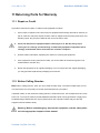
11.1
Repair or Credit .................................................................................................................... 44
11.2
Before Calling Gonotec ........................................................................................................ 44
12
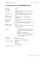
Specifications of the OSMOMAT 050 .........................45
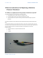
13
Service Instructions for Replacing a Defective
®
Pressure Transducer ...................................................46
13.1
When is a replacement of the pressure transducer required? ............................................. 46
13.2
Instructions ........................................................................................................................... 47
13.2.1
13.2.2
Disassembly ......................................................................................................................... 47
Assembly .............................................................................................................................. 49
Version 1.1 (2011-10-12)
Page 6 of 51
OSMOMAT 050 User Guide
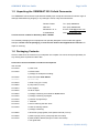
1 Introduction
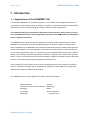
1.1 Applications of the OSMOMAT 050
®
The Gonotec OSMOMAT 050 colloid osmometer is a non-invasive in vitro diagnostic device for invitro analysis of human blood and other samples. Its purpose is to provide information to help identify,
diagnose, monitor and treat physiological conditions, states of health, and diseases.
The equipment may only be operated by specialists or those persons whose training or skills
have provided them with the necessary practical experience (see MPBetreibV: German Medical
Devices Operator Ordinance).
The OSMOMAT 050 colloid osmometer is particularly suited for routine measurements in medical
applications as well as the molecular weight determination in aqueous solutions in industry and research applications. The OSMOMAT 050 colloid osmometer determines the colloid osmotic pressure
(COP) of blood plasma. The main diagnostic considerations for determining the colloid osmotic pressure in medical applications apply e.g. in case of blood loss, hyperalbuminemia, as well as in albumin
therapy to prevent lung edemas and all diseases resulting in changes to the colloid osmotic pressure.
Approx. 150 µL of a sample solution are required, making it suitable for measuring even small sample
volumes. The measuring speed permits rapid series measurements.
In the hospital, the colloid osmotic pressure is an important parameter among others for monitoring
infusion- and dilution therapies and for diagnosing anomalies in the water balance thus supporting
decisions with respect to additional examinations.
The OSMOMAT 050 has been applied successfully in the following fields:
Clinical pediatrics
Urology
Anesthesia / intensive care medicine
Nephrology
Cardiology
Botany
Gynecology
Clinical chemistry
Physiology
4 and many more
Version 1.1 (2011-10-12)
OSMOMAT 050 User Guide
Page 7 of 51
1.2 Application Restrictions of the OSMOMAT 050
The OSMOMAT 050 is not suitable for measuring whole blood samples.
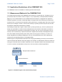
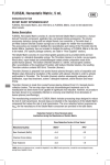
1.3 Measurement Method of the OSMOMAT 050
The measurement principle of the OSMOMAT 050 is based on a measuring cell, consisting of an upper and lower half, each with a volume of approx. 10 µL, separated by a semipermeable membrane
(Fig. 1-1). The so-called reference cell, located below the membrane, is equipped with a pressure
transducer (pressure converter, measuring bridge). The upper half of the measuring cell, also known
as sample cell, is connected to the automatic rinsing mechanism. In standby state, both cells contain a
solvent (such as Ringer's solution, isotonic NaCl solution) to prevent pressure drops and ensure that
the pressure measurement membrane is relaxed.
After adding a sample with a higher colloid osmotic (oncotic) pressure (e.g. serum or plasma) to the
sample cell, permeation of solvent causes underpressure in the reference cell based on the laws of
osmosis (because the membrane is impenetrable to proteins, this can only be achieved by a flow of
solvent). This is measured by a pressure transducer, amplified electronically, and displayed as positive, direct colloid osmotic pressure (COP value), either in mm Hg (mm of mercury), cm H2O, or kPascal. By default, the reading is displayed in mm Hg. The measurement unit can be switched by
pressing the corresponding buttons on the digital display.
Different types of semipermeable membranes with varying permeability ("pore size") can be used for
macro molecules with different molecular weights. This results in a characteristic reference number for
each type of membrane (the so-called "membrane cut-off", indicated in dalton units). Membranes with
a cut-off of 10,000 or 20,000 dalton have proven to be very useful in practical applications.
Sample cell
Semipermeable membrane
Reference cell
Pressure transducer
Amplifier
Display
Figure 1-1: Schematic figure of the measuremet principle
Version 1.1 (2011-10-12)
Page 8 of 51
OSMOMAT 050 User Guide
1.4 Reproducibility of the OSMOMAT 050
Measurement display
3 digits
Measuring range
73 mm HG, 100 cm water column, or 9.99 kPa
Resolution
0.1 mm HG over the entire measurement range
Reproducibility
< ±0.5 mm HG
Version 1.1 (2011-10-12)
OSMOMAT 050 User Guide
Page 9 of 51
1.5 Unpacking the OSMOMAT 050 Colloid Osmometer
The OSMOMAT 050 should be unpacked immediately upon receipt and checked for obvious signs of
damage sustained during shipping. If any damage is found, notify the manufacturer:
Gonotec GmbH
Tel.: (030) 7809588-0
GSG-Hof
Fax: (030) 7809588-88
Reuchlinstr. 10-11
E-mail: [email protected]
D-10553 Berlin
Web: www.gonotec.com
Toll-free service number for Germany: 0800 / 7846027
The reusable packaging for this equipment was specially designed to ensure safe and hygienic
transport. Please save the packaging in case the unit needs to be shipped back to Gonotec for
repair or servicing.
1.6 Packaging Contents
Check to make sure the contents of your shipment are complete. We cannot accept responsibility for
any missing items reported at a later date.
Accessories and consumables included in the shipment
Item number
20.9.0100
1 power cord
20.9.0160
1 RS-232 cable
1 package of small parts including:
00.9.0102
2 fine-wire fuses 230V 250mA
00.9.0104
(at 110V 0.5A)
50.9.0040
1 small O ring (26 x 2 mm)
50.9.0060
2 pump tubes (9.5 cm)
50.9.0070
2 tube nipples
50.9.0030
10 silicon septa
50.9.0020
1 package containing 5 membranes 20,000 dalton
50.9.0160
1 package containing 2 plungers
50.9.0100
1 precision syringe 250 µL
50.9.0150
1 tweezers
50.9.0140
1 tool for widening the tube ends
50.9.0180
1 bottle of cleaning solution
(
1 package containing:
50.9.0080
1 tuberculin syringe (plastic) with special cannula (16 mm)
50.9.0090
1 plastic syringe (30 mL) with pump tube and clamp
50.9.0130
2 plastic bottles, labeled (Ringer's solution and waste)
1 user guide 050
Version 1.1 (2011-10-12)
Page 10 of 51
OSMOMAT 050 User Guide
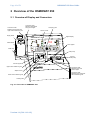
2 Overview of the OSMOMAT 050
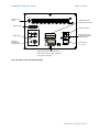
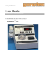
2.1 Overview of Display and Connectors
Connection tube
between supply bottle and
upper half of measuring cell
Connection tube
between waste bottle
and ground nipple
Clamping yoke
Tension screw
Supply bottle
INJECT
RESULT
Waste bottle
2 RESULT
Digital display
Colloid Osmometer
.
OSMOM AT 050
mm Hg
23 2
cm H2O
k-PASCAL
Tube nipples
STAND BY
RESET
SERIES
CALIBRATION
RESULT CHECK
START
BUSY
Bottle tray
4
3
1
OVER LOAD
RINSING
MEASURING
Tube pump
5
6
Tube for
tube pump
7
8
Ground nipple
Upper half of measuring cell
Connection tube
between pump and
ground nipple
Septum screw
Lower half of measuring cell
Leveling disk
Fig. 2-1: Front view of OSMOMAT 050
Version 1.1 (2011-10-12)
Connection tube
between pump and upper
half of measuring cell
OSMOMAT 050 User Guide
Page 11 of 51
Pumpe
Manual pump
control
Characteristics for
device fuse to be used
RS232 output
Power connection
Recorder Output
23 4
1 5
Sicherungen / Fuse
110 V - 500 mA LAG
Analog output
230 V - 250 mA LAG
Fuse
Fuse holder for twophase fuse protection
of power supply
0
Alignment
potentiometer
for analog port
I
Power switch
1/on 0/off
Serial number plate with information on
serial number, power voltage, frequency
and power consumption
Fig. 2-2: Rear view of the Osmomat 050
Version 1.1 (2011-10-12)
Page 12 of 51
OSMOMAT 050 User Guide
2.2 Power Supply
The standard model is operated with 230V (+/- 30V) at 50/60 Hz. The power consumption is 20VA.
Special models using 115V or 100V are also available.
2.3 Dimensions and Weight
Dimensions (width x height x depth):
360 x 250 x 355 mm
Weight: approx. 5.1 kg excluding bottles
2.4 Safety and Handling Information
The OSMOMAT 050 colloid osmometer is an electric laboratory measurement device. It should therefore be handled according to the safety provisions and precautions for electric measurement, control,
and laboratory equipment.
If the equipment is to be decommissioned, make sure it is sufficiently disinfected. This will
make sure that the equipment has been decommissioned in accordance with local accident
prevention guidelines (UVV).
To prevent damage to the pressure transducer during extended periods of inactivity or in case of decommissioning, the following steps must be performed:
Always switch on device when performing work on the measuring cell or the pressure transducer (see chapter 3).
Open measuring cell and remove membrane and filter paper.
Repeatedly rinse measuring cell using distilled water (especially the pressure transducer).
Suction off residual water using special cannula, dry cell by using paper, and loosely replace
screw cap with dry filter paper inserted.
The unit does not emit harmful substances either during operation or when switched off.
Symbols on the unit and serial number plate correspond to the requirements of the following standards: DIN EN 61010-1, DIN EN 375 and DIN EN 980 (harmonized standard for medical devices according to § 3 No. 17 of the German Medical Device Law MPG).
2.5 Known Risks Associated with the Use of the OSMOMAT 050
In our experience using the OSMOMAT since 1979, we have not found it to present any direct hazards
or risks to the user. Such hazards and risks cannot be excluded entirely for technical equipment, however.
This operating instruction helps you gain a basic understanding of the design, the measurement principle, maintenance and servicing of the unit.
Version 1.1 (2011-10-12)
OSMOMAT 050 User Guide
Page 13 of 51
3 Setup and Initial Operation
The unit must be placed in a location free from vibrations and must be protected from direct sources
of heat such as sunlight, heaters or furnaces. The ambient temperature should be between 10°C and
35°C (50-95°F).
It is strictly necessary to place the device on a very sturdy surface. Otherwise, the sensitive pressure
measurement and the automatic end point detection may be disturbed.
Use the power cord provided to connect the OSMOMAT 050 from the power connector on the back of
the unit to a power outlet. Make sure the unit’s ground is enabled via the shockproof grounding.
If the power cord plug does not match the conventional power outlets in your location, you may substitute another power cord. It is essential, however, that the cable’s green/yellow wire is connected to the
safety grounding.
It is also important to ensure that the voltage indicated on the serial number plate
matches that of your electricity network. Incorrect voltage will cause the fuse in the
power supply unit to blow.
The OSMOMAT 050 can now be switched on via the power switch on the back of the unit (next to the
power connector).
All work (unscrewing, screwing together or adding solvents) must only be performed
with the device switched on and in calibration mode (can be set by pressing the “CALIBRATION” button).
Excess pressure which may result in the destruction of the pressure transducer is indicated on the
display. This happens in three stages. In the first stage, the display shows 99.9 and flashes. If the
pressure increases, the "overload" LED lights up in the second stage. If the pressure still increases, an
alarm sounds. When the alarm sounds, the pressure gauge is at approx. 50% of the burst pressure. If
you continue to screw together or open the system, the highly sensitive pressure transducer will be
destroyed.
The WARRANTY is voided for a pressure transducer destroyed due to over- or underpressure.
Before beginning an initial measurement, you must add solvent to the measuring cell, insert
the prepared membrane, and calibrate the device (see chapter 4 and 5).
When the measuring cell is filled and the membrane is inserted, the device is in standby mode and
ready for measurement, indicated by the green standby-LED.
You can start the measurement by pressing the “START” button. This will check the zero point internally and prompt the user to inject the sample after approx. 10 seconds (indicated by the flashing INJECT LED and the LED on the measuring cell).
The device should always remain switched on while the measuring cell is filled and closed, even if it is
not used for an extended period of time. The system automatically rinses the measuring cell at regular
intervals, keeping the OSMOMAT 050 ready for measurement.
Version 1.1 (2011-10-12)
Page 14 of 51
OSMOMAT 050 User Guide
While the device is not in use, the measuring cell may dry out, especially in the area of
the pressure transducer. The salt crystals that form adhere to the pressure measurement membrane and can destroy it. Regular rinsing prevents the drying out.
Make sure to top off the Ringer's solution and empty the waste bottle regularly.
If the device is left in standby mode for an extended period of time without topping of
the Ringer's solution, the measuring cell will dry out quickly, which may result in the
destruction of the pressure measurement membrane.
If the device is not used for an extended period of time (several weeks), the measuring
cell must be opened and rinsed using distilled water. Afterwards, the device can be
switched off.
When When working on the pressure transducer, the device must always be switched on.
Version 1.1 (2011-10-12)
OSMOMAT 050 User Guide
Page 15 of 51
4 Preparing the Measuring cell for Measurement
To prepare the measuring cell, you need the tools and accessories included with the standard accessories as well as a suitable solvent, distilled water and the prepared semipermeable membrane and
filter paper (see chapter 4.4).
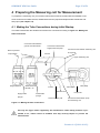
4.1 Making the Tube Connections during Initial Startup
The tubes included with the standard accessories are connected according to Figure 4-1: Making the
tube connections.
Connection tube between
ground and waste bottle
Connection tube between
supply bottle and pump
Connection tube between measuring cell
Bore for pressure
compensation
and ground
Ground
Upper measuring cell
Ringer's solution
Waste, minimum
fill level 1 cm
Tube nipples
T screw
Tube pump
Septum screw
Supply bottle
Waste bottle
plunger
plunger
Pump tube
Lower measuring cell
Connection tube between pump
and measuring cell
Figure 4-1: Making the tube connections
Use only the Tygon tubes supplied by the manufacturer. Other tubing material is permeable to air, which causes air bubbles that may severely impact or prevent the
measurement.
Version 1.1 (2011-10-12)
Page 16 of 51
OSMOMAT 050 User Guide
The tubes are pushed onto the stainless steel tubes by about 5 mm. The tool for widening the tube
ends (50.9. 0140) included with the standard accessories is used for this purpose. The tube end is
held using sandpaper and widened using the moistened tip of the tool.
The connection tubes for the supply and waste bottles are passed through a bore of the unscrewed
cap and pushed onto the corresponding plungers (Figure 4-2). The plungers hold the tubes on the
bottom of the bottles. The second opening on the cap provides unrestricted atmospheric pressure
compensation.
Figure 4-2: Plunger
Tube lengths
Connection tube between supply bottle and pump
59 cm
Connection tube between ground bolt and waste bottle
45 cm
Connection tube between pump and measuring cell
6 cm
Connection tube between measuring cell and ground bolt
5 cm
Pump tube
9,5 cm
Table 4-1 Tube lengths
Version 1.1 (2011-10-12)
OSMOMAT 050 User Guide
Page 17 of 51
4.2 Ringer's Solution as Solvent
The Ringer's solution should be a pure Ringer's electrolyte solution without added lactates or other
substances. If necessary, the solution can be self made.
Sodium chloride
0,8 g
Potassium chloride
0,02 g
Calcium chloride
0,02 g
Sodium bicarbonate
0,1 g
use distilled water to fill up to
100 cm³
In exceptional cases, you can also use an isotonic saline solution with a concentration of 0.9% NaCl.
The solvent used for preparing the lower half of the measuring cell must not contain any amount of
solved gas/air. If necessary, it must first be degassed by heating up just under the boiling point or by
degassing under vacuum. We recommend using the 30 mL plastic syringe included in the accessories
for a simple way to degas the solvent ( Figure 4-3).
Figure 4-3: Plastic syringe with tube clamp
Approx. 20 mL of the solvent are aspirated using the connected silicon rubber tube. Next, the tube is
clamped shut using the tube clamp and a vacuum is created by firmly pulling the syringe plunger. The
liquid is shaken and then the tube clamp is opened again. The gas can escape. This operation is repeated three to four times to degas the solvent. The degassed solvent is later added to the lower half
of the cell directly from the syringe (Figure 4-8)
Version 1.1 (2011-10-12)
Page 18 of 51
OSMOMAT 050 User Guide
4.3 Filling the Supply and Waste Bottles
Add the Ringer's solution mentioned earlier to the supply bottle and screw on the cap.
Place the supply bottle in the rear position on the bottle tray.
The waste bottle collects the measured sample and the used solvent required to rinse the measuring
cell. The waste bottle must have a constant fill level of minimum 10 mm required during measurement and calibration as hydrostatic reference value for the zero point.
For safety reasons (risk of infection), we recommend adding a small amount of a commercially available disinfectant and daily emptying and rinsing of the bottle when the device is in use.
4.4 Preparing the Semipermeable Membrane
4.4.1 Selecting suitable membranes
The semipermeable membrane is a main component of the osmotic cell. The defined pore size allows
only the lower molecular solvent and the electrolytes to permeate, while the higher molecular substances of the measurement solution are retained. In addition, the membrane material seals the osmotic cell.
The pore size or pore size range is the typical factor for the retention and is called "cut-off". The membranes used for membrane osmometry usually have a cut-off between 5,000 and 30,000 dalton. The
pore sizes specified by the membrane manufacturers are reference values only. They do not indicate
the actual pore size or an existing pore size distribution.
Increasing the cut-off may result in lower colloid osmotic pressures.
Only membranes with very thin layers containing a supporting material for mechanical reasons
(so-called two-layer membranes) can provide adequate permeability. Depending on the manufacturer,
both layers are made of the same or different materials. Aqueous solutions can be used for virtually all
membrane materials.
It is strictly necessary that the membrane has a diameter of 25 mm [+0, -0.5 mm]!
Membranes from other manufacturers can be slightly bigger and in that case must be trimmed with
scissors.
We recommend a membrane material with a cut-off (retention)
of higher than 10,000 g/Mol
and
of higher than 20,000 g/Mol.
The membranes are typically supplied dry with the pores filled with glycerin. The dry membranes supplied by Gonotec are each separated by filter paper. The membrane must be conditioned in water
before installation in the measuring cell of the OSMOMAT 050.
Version 1.1 (2011-10-12)
OSMOMAT 050 User Guide
Page 19 of 51
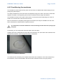
4.4.2 Conditioning the membrane
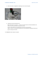
The membrane is placed with the shiny side onto the surface of distilled water while keeping the supporting layer (dull side) dry.
The water penetrates the pores from below and displaces the glycerin. After a short time, small water
droplets are visible on the supporting side, and the membrane shows a slight discoloration.
The membrane remains on the water surface until it is evenly discolored. Depending on the pore diameter, this can take from a few seconds to an hour.
Next, the membrane is completely submerged into the water and ready for installation into the membrane osmometer for measurement of aqueous solvents.
It is important to install the membrane in the measuring cell with the active (shiny) layer
facing up.
If necessary, you can verify which of the two sides is the active layer.
Carefully remove the membrane from the water using tweezers. The active side of the membrane has
hydrophobic properties, while the supporting layer is hydrophilic.
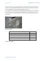
Figure 4-4: Conditioned membrane
The white spot was caused by an air bubble located below the membrane. In this case, briefly lift up
the membrane, remove the air bubble, and wait until the membrane has an even gray coloring.
Version 1.1 (2011-10-12)
Page 20 of 51
OSMOMAT 050 User Guide
4.5 Preparing the Filter Paper and Degassing the Solvent
A piece of filter paper must be placed below the semipermeable membrane to act as a leveling disk for
the membranes recommended by us. This filter paper increases the small thickness of the membranes
from 0.10 to 0.15 mm to an overall thickness of 0.3 mm and creates the correct bonding pressure
when screwing together the measuring cell.
The filter paper is not required when using membranes with a thickness of 0.3 mm.
It is supplied by us along with the membranes and acts as a separating layer between the membranes.
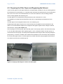
The filter paper must be degassed before use in the measuring cell.
Degassing the filter paper requires a lot of care because all air bubbles must be removed from the
paper. It is recommended to degase use to degas the filter paper together with the Ringer's solution
with the 30 mL syringe (see chapter 4.2)
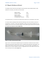
Pull the plunger out of the syringe, place the filter paper in the syringe cylinder, and reinsert the plunger. Do not fold the filter paper. Next, aspirate approx. 15 mL of Ringer's solution into the syringe, remove the air from the syringe, and clamp shut the aspiration tube using the tube clamp. By pulling the
plunger firmly, a vacuum is created, which causes steam bubbles to form and removes the remaining
air from the filter paper texture. The filter paper may remain inside the syringe together with the Ringer's solution until used in the measuring cell.
Figure 4-5: Syringe with Ringer's solution and filter paper
Version 1.1 (2011-10-12)
OSMOMAT 050 User Guide
Page 21 of 51
4.6 Opening the Measuring cell
As described in chapter 3, you must first switch on the device. Press the "CALIBRATION" button
to check the pressure ratios and protect the pressure transducer. The indicator light of the button lights
up, and after approx. 10-20 seconds the digital display shows "00.0". The display has a direct connection to the pressure gauge and shows the pressure ratios of the pressure transducer.
4.6.1 Initial Startup with Dry Measuring cell
When the system is delivered, a piece of filter paper is placed in the lower half of the measuring cell to
prevent damage during shipping. To open the measuring cell, loosen the tension screw and flip back
the clamping yoke. Then remove the upper half of the measuring cell.
Remove the O ring and the filter paper from the cell. It will be reused during assembly.
4.6.2 Removing the Membrane When the Measuring cell is Filled
If the measuring cell is already filled, great care must be taken during unscrewing while closely monitoring the pressure reading. If the alarm sounds, stop unscrewing immediately. After pressure compensation, the alarm is silenced and you can proceed to open carefully. Loosen the tension screw, flip
back the clamping yoke, and remove the upper half of the measuring cell.
Remove the O ring and the old membrane together with the filter paper using the tweezers. Clean the
O-ring with water and keep it immersed in water until installation.
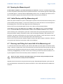
4.7 Cleaning and Filling the Lower Half of the Measuring cell
To clean the lower half of the measuring cell, first fill it with water up to the upper rim and then clean it
using a cotton tip or paper tissue. Next, fill it with ethanol and insert the tuberculin syringe with special
cannula (from the standard accessories) into the vertical bore at the bottom of the lower half of the
measuring cell (Figure 4-6). This bore connects the measuring cell with the pressure transducer. Using the supplied cannula ensures that the pressure membrane is not destroyed.
Never use other cannulas, especially longer ones, because they would puncture the
delicate membrane of the pressure transducer.
Aspirate ethanol into the bore using the tuberculin syringe. Repeated eject/aspirate cycles clean the
bore and deaerate the area above the pressure transducer, which means that all the air bubbles are
removed.
Version 1.1 (2011-10-12)
Page 22 of 51
OSMOMAT 050 User Guide
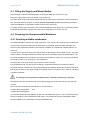
Next, immediately remove the ethanol using a paper tissue (Figure 4-7) and add distilled water.
If the alcohol remains in the measuring cell too long, it affects the plastic material, which becomes opaque.
.
Figure 4-6: Filling the lower measuring cell
Figure 4-7: Cleaning the lower measuring cell
Use the tuberculin syringe again to aspirate the distilled water into the bore in the lower half of the
measuring cell. Watch closely to ensure that no air bubbles form. Next, remove the water from the
measuring cell using a paper tissue.
Figure 4-8: Adding the degassed solvent
The lower half of the measuring cell is now cleaned, and you can add the solvent.
Use the 30 mL syringe to add the degassed Ringer's solution (Figure 4-5). After adding the degassed
solvent, rinse the bore of the lower half of the measuring cell using the tuberculin syringe again. During injection, do not push the syringe plunger all the way to the end to prevent air bubbles from being
pushed into the bore.
Version 1.1 (2011-10-12)
OSMOMAT 050 User Guide
Page 23 of 51
The purpose of this cleaning procedure is to free the entire bottom of the measuring cell as well as the
bore and the area above the pressure transducer from tiny adhering air bubbles. Air bubbles in the
measurement system prolong the measuring time and falsify the measurement result.
4.8 Screwing Together the Measuring cell
Add degassed Ringer's solution up to the rim of the cleaned and deaerated lower half of the measuring cell. Install the O ring (26 mm). Next, remove the degassed filter paper from the 30 mL syringe and
place it at the bottom of the measuring cell without air bubbles. Remove the conditioned semipermeable membrane from the water, flip it once, and place it on top of the filter paper in the measuring cell
with the active side facing up. Carefully push it down with a finger so that it is positioned precisely in
the center of the measuring cell (Figure 4-10).
Now, you can install the upper half of the measuring cell (Figure 4-9). Rest the upper measuring cell
on the rear edge and carefully lower it toward the front. No air bubbles must be visible inside the
O ring. Use a finger to secure the upper half of the measuring cell (Figure 4-11). Fold the clamping
yoke over the cell and tighten it very carefully.
Figure 4-10: Installed membrane and O ring
Figure 4-9: Installing the upper measuring
cell
Figure 4-11: Securing the upper measuring cell
Version 1.1 (2011-10-12)
Page 24 of 51
OSMOMAT 050 User Guide
Screwing together the measuring cell results in significant overpressure in the lower half of the cell.
This overpressure decreases quickly because the solvent permeates through the pores of the semipermeable membrane. The screwing together is performed manually without tools.
The overpressure created during this operation can easily destroy the sensitive pressure transducer.
Therefore, the measuring cell has to be screwed together carefully in small intervals.
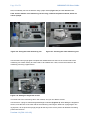
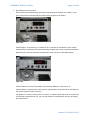
If the pressure increases to above 99.9 cm water column, the display starts flashing (Figure 4-12). If
the pressure increases further to approx. 550 cm water column, the "overload" warning light comes on
(Figure 4-13). When an alarm sounds, you must immediately stop the screwing operation, otherwise
the pressure transducer will be destroyed. You may resume after the pressure has decreased enough
so that the "overload" LED goes off.
Figure 4-12: Overpressure indicated by flashing
Figure 4-13: Overpressure indicated by
digits
"overload" LED
The measuring cell is screwed together in small increments until the end stop is reached by firmly
turning by hand.
Version 1.1 (2011-10-12)
OSMOMAT 050 User Guide
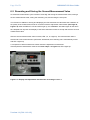
Page 25 of 51
This dark ring must be evenly visible
Figure 4-14: Upper measuring cell completely tightened
The semipermeable membrane becomes slightly transparent and a uniform, somewhat dark ring is
visible at the edge of the membrane (Figure 4-14).
The displaced Ringer's solution, collected in the overflow channel of the lower half of the measuring
cell, can be removed using a paper tissue.
Version 1.1 (2011-10-12)
Page 26 of 51
OSMOMAT 050 User Guide
5 Calibrating the OSMOMAT 050
5.1 Calibration Using the Hydrostatic Pressure Difference
The prerequisite for calibrating the OSMOMAT 050 is the assembly of the measurement system according to chapter 4.8 and the stabilization of the pressure inside the cell.
Calibration is performed directly by creating a hydrostatic pressure difference.
To fill all tubes without air bubbles, press the "Pumpe" button at the back panel until the tube going to
the waste bottle is also filled without air bubbles.
Calibration procedure:
1. Press the "RESET" button. The measurement system is rinsed again and the "STAND BY"
LED lights up.
Figure 5-1: Reset
2. Press the "CALIBRATION" button. The display automatically changes to cm water column,
irrespective of the measurement unit set.
Figure 5-2: Calibration
Version 1.1 (2011-10-12)
Figure 5-3: Display 00.0 in cmH2O
OSMOMAT 050 User Guide
Page 27 of 51
After a few seconds, the display shows "00.0". The baseline of the measurement system for the value
"00.0" is set with the fill level taken into account. The waste bottle must be placed on the bottle tray
and the tube system has to be filled without air bubbles.
3. Move the bottle from the tray to the table surface. The height difference between tray and table surface is exactly 10 cm. Setting a stable measurement value of approx. 10 cm water column should not take longer than 10 seconds.
Figure 5-4: Setting the value for 10 cm water column
4. Adjusting the potentiometer will set the measurement value to exactly 10.00 cm water column.
Figure 5-5: Adjustment to 10 cm water column
Version 1.1 (2011-10-12)
Page 28 of 51
OSMOMAT 050 User Guide
5. To verify the correct setting, move the bottle back to the tray. This will revert to the zero point.
Figure 5-6: Checking the zero point
The setting of the zero point should also take less than 10 seconds. The measurement system is still
subject to a slight drift directly after installing the membrane. The zero point deviates slightly.
Therefore, calibration shouldn't be performed until the pressure ratios have completely stabilized. Also,
it should be repeated once or twice.
6 Measuring the Colloid Osmotic Pressure
6.1 Prerequisites for Measurement
The OSMOMAT 050 prepared according to item 4 and calibrated according to item 5 as well as a
precision syringe with special cannula for injecting the sample (included with the accessories: order
no. 50.9.0100) are required to perform a measurement. This special cannula has a needle-shaped tip
with a lateral opening which creates a clean, self-sealing hole when puncturing the silicon septum.
Standard injection cannulas cut out rubber particles during injection, clogging the measuring cell and
rendering the silicon septum unusable.
The STANDBY LED indicates that the OSMOMAT 050 is ready for measurement.
If the unit was not used for an extended period of time, you should press the “RESET” button prior to
measurement. This will rinse the measuring cell and reset the zero point.
Version 1.1 (2011-10-12)
OSMOMAT 050 User Guide
Page 29 of 51
6.2 Sample Material
Any aqueous sample with macro molecules can be measured. In medical applications, the colloid
osmotic pressure of blood samples is measured.
To prevent coagulation, heparin should be added to the plasma sample. The dosage should be below
100 units/mL. "Excessive heparin concentrations as well as using other anticoagulative additives such
as EDTA or sodium citrate result in false high values for the colloid osmotic pressure.
To obtain the plasma, the blood should be centrifuged soon after collection and stored at 4°C in the
refrigerator."
1
“Storage for up to 7 days is possible without significant changes to the colloid osmotic pressure. However, the sample should not be frozen”.
2
The minimum sample volume required is 150 µL.
“The samples must be homogeneous and should have the same temperature as the measurement
device when measuring the colloid osmotic pressure. Cooled samples with a temperature difference of
almost 20°C compared to the measurement device exhibit significant differences when measuring the
colloid osmotic pressure”.
3
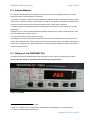
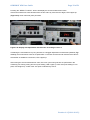
6.3 Display of the OSMOMAT 050
The figure below shows labeled buttons and LEDs and serves to clarify the measuring procedure.
Please read this chapter completely before performing a measurement.
Figure 6-1: Display
1
A. Grünert: Der kolloidosmotische Druck
2
Marty, A T: Plasma oncotic variation and cardiopulmonary independence in normal humans
3
A. Grünert: Der kolloidosmotische Druck
Version 1.1 (2011-10-12)
Page 30 of 51
OSMOMAT 050 User Guide
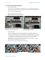
6.4 Performing the Measurement
1. Press the START button.
The zero point is re-checked internally, indicated by "BUSY"- LED lighting up (Fig. 6-2). After
approx. 10 seconds, the “INJECT”- LED and the LED on the lower measuring cell flash and
prompt to inject the sample (Fig. 6-3).
2. Aspirate a sample volume of 150-250 µL
Make sure to fill the syringe without air bubbles.
Figure 6-2: Checking the zero point
Figure 6-3: Injection prompt
3. Injecting the sample
Insert the cannula through the septum as far as it will go. It is impossible to puncture the
membrane during this procedure. Inject the sample into the measuring cell using three equal
cycles of approx. 50 µL (Fig. 6-4). This push-injection increases the rinsing effect and creates
an overpressure which is the trigger impulse to start the measurement program of the
OSMOMAT 050. It must be prevented to inject air bubbles or foam. Therefore, the syringe
plunger should not be pushed all the way to the end.
After injection, remove the syringe and clean it using water.
Figure 6-4: Injection in three stages
Version 1.1 (2011-10-12)
OSMOMAT 050 User Guide
Page 31 of 51
4. Recording the pressure value
After inserting the needle through the septum and injecting the sample, the “INJECT”- LED
goes off and LED 2 indicates that the measurement sequence has started.
Figure 6-5
It takes approx. 30 seconds up to a maximum of 4.5 minutes for the balance of the osmotic
underpressure to stabilize in the lower measuring cell filled with solvent. This balanced state is
detected by the electronics and the measurement value is shown on the digital display.
Figure 6-6
At the same time, the LED 2 and LED 3 go off and the “RESULT”- LED comes on.
This presents the measurement result, which is representative of the osmolal concentration of
the colloids (colloid osmotic pressure).
The display is in mmHg. Pressing the "cm H2O" or "k-Pascal" button will show the result in the
corresponding measurement unit. You can also select the measurement unit prior to starting
the measurement.
Version 1.1 (2011-10-12)
Page 32 of 51
OSMOMAT 050 User Guide
6.5 Recording and Storing the Second Measurement Value
An automatic measurement cycle consists of recording and storing the measurement result, storing a
second measurement result, rinsing the measuring cell, and checking the zero point.
The functions in addition to storing and displaying the first measurement value allow the evaluation of
the quality of the measurement result in connection with the adjustment characteristic (see Page 34,
Figure 6.9). After the RESULT LED and LED 3 light up, the OSMOMAT 050 waits again for the same
time elapsed from injection until display of the first measurement value to accept and store the second
measurement value.
After the second measurement value is stored, LED 4, 5, or 6 light up. The measurement value is
stored until a new measurement is performed. Afterwards, the measuring cell is automatically rinsed
and LED 7 lights up.
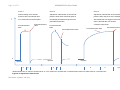
A comparison of both measurement values shows the adjustment characteristic.
If the adjustment characteristic matches the curve shape 1 in Figure 6.9, LED 5 lights up.
Figure 6-7: Display with adjustment characteristic according to curve 1
Version 1.1 (2011-10-12)
OSMOMAT 050 User Guide
Page 33 of 51
Pressing the “RESULT CHECK”- button will display the second measurement value.
If the 2nd measurement value deviates from the first value by more than two digits, LED 6 lights up
(Figure 6-8), lower molecular parts permeate.
Figure 6-8: Display with adjustment characteristic according to curve 2
If obtaining the result takes a very long time due to a sluggish adjustment characteristic (curve 3, Figure 6.9), the measurement value is accepted after 4.5 minutes and the second measurement value is
stored after an additional 4.5 minutes, LED 4 lights up.
After storing the second measurement value, five rinse cycles using solvent are performed in the
measuring cell. During rinsing and zero point setting, LED 7 lights up. After zero point setting is complete, LED 8 lights up. A shift of the zero point is indicated by LED 9.
Version 1.1 (2011-10-12)
Page 34 of 51
OSMOMAT 050 User Guide
Curve 1
Curve 2
Curve 3
Normal setting of the osmotic
Adjustment characteristic of the osmotic
Adjustment characteristic of the osmotic
pressure when the sample does
pressure when lower molecular parts of
pressure when the pores of the semiperme-
not contain lower molecular parts
the sample permeate through the semi-
able membrane are clogged. The measure-
permeable membrane
ment is aborted after 4.5 minutes,
1st measurement
value
2nd measurement
value
9 minutes respectively.
1st measurement
value
2nd measurement value
2nd measurement value
1st measurement value
0
Injection
Injection
a
b
Injection
a
b
a
b
Measurement time "a" always corresponds to "b". The criterion for recording the 1st measurement value is a stable value or a reversal point.
Figure 6-9: Adjustment characteristic
Version 1.1 (2011-10-12)
t (min)
OSMOMAT 050 User Guide
Page 35 of 51
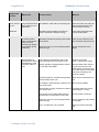
7 Classification of Malfunctions by ComponentGroup
The following presents an overview of the individual component groups, identifying the function of
each component, its potential malfunctions, the effects of the malfunctions on the measurement system, the possible causes of the malfunctions and the procedure for correcting each malfunction.
Some errors can be remedied directly by the user or an in-house medical equipment technician; other
errors require return of the unit to the manufacturer.
Version 1.1 (2011-10-12)
Page 36 of 51
Components
Function
Lower measuring cell
Malfunction
OSMOMAT 050 User Guide
Possible Cause
Long adjustment time Air bubbles in lower half of measuring cell
after inserting a new
membrane
Membrane
Measure
Open and clean cell again, fill
with degassed solvent and
insert a new membrane
Membrane impermeable (pore size too
small or membrane stored too long)
Insert fresh membrane with
cut-off 20,000 dalton
No measurement
value: measurement
value is 0 when
measuring a sample
(no problems during
calibration)
Membrane inserted incorrectly (active side
facing down)
Insert a new membrane into
the cell (active side facing up)
Measuring cell is not yet screwed together
tightly enough
Screw cell together more
tightly
Reproducibility of
measurement value is
unsatisfactory (measurement value too
low)
Pump tube too old (flagged). Part of the
injected sample flows toward the pump
Replace pump tube
Clean / replace tube nipple
System partially clogged between measuring cell and waste bottle
All tubes behind the measuring cell, the plunger of the
waste bottle, the channel and
the outlet cannula in the upper
half of the measuring cell
must be cleaned
Strong fluctuations of ambient temperature
(direct sunlight, draft, etc.)
Move device to different location
Air bubbles in tube between measuring cell Rinse out air bubbles
and waste bottle
Waste bottle is empty, therefore no defined Fill waste bottle with a bit of
zero point exists
water (approx. 10 mm)
Version 1.1 (2011-10-12)
The plunger in the waste bottle does not
hold the tube on the bottom of the bottle
Check position of plunger
Measuring cell is not yet screwed together
tightly enough
Screw measuring cell together
more tightly
Entry of measuring cell is clogged
Open and clean measuring
cell
OSMOMAT 050 User Guide
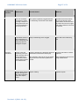
Components
Function
Pressure
transducer
Malfunction
Page 37 of 51
Possible Cause
Measure
The red "Overload"
The system is partially clogged between
LED lights up (when
the measuring cell and the waste bottle
injecting a sample or
during automatic rinsing of the measuring
cell using solvent)
All tubes behind the measuring cell, the plunger of the
waste bottle, the channel and
the outlet cannula in the upper
half of the measuring cell must
be cleaned
Liquid leaks from the
tube connection between measuring cell
and pump when injecting the sample
Entry of measuring cell is clogged
Open and clean measuring
cell
Device rinses the
measuring cell in periodic intervals and no
longer switches to
STAND-BY position
Device finds no baseline characteristic
Pressure transducer is defective (pressure
measurement membrane destroyed)
Pressure transducer must be
replaced
The measuring cell was dry for an extended period of time and salt crystals have
formed
Open measuring cell and rinse
using distilled water
Solvent leaks from the Septum leaking
septum during injection. Salt crust forms
below the septum
screw
Version 1.1 (2011-10-12)
Replace septum
Page 38 of 51
OSMOMAT 050 User Guide
8 Maintenance of the OSMOMAT 050
8.1 Requirements of the Medical Devices Operator Ordinance
The regulatory scope of Germany’s Medical Devices Operator Ordinance includes the maintenance
and servicing of medical devices. Sections 2 (Special Regulations for Active Medical Devices)
and 3 (Medical Devices with Measurement Functions) regulate the safety and measurement
checks to be performed on medical devices.
These checks are mandatory for medical devices listed in Annexes 1 and 2 of the Medical Devices
Operator Ordinance.
8.2 Safety Checks (§ 6 of Medical Devices Operator Ordinance)
The OSMOMAT 050 is not listed in Annex 1 of the Medical Devices Operator Ordinance. Public authorities do not require the unit to undergo safety checks.
Safety checks should be conducted by the on-site safety coordinator in accordance
with relevant accident prevention guidelines.
8.3 Measurement Checks (§ 11 of Medical Devices Operator
Ordinance
The Osmomat 050 is not listed in Annex 2 of the Medical Devices Operator Ordinance. No measurement checks are stipulated by the Ordinance.
Nonetheless, the user should perform the following checks:
•
Checking and filling the solvent bottle
•
Emptying the waste bottle
•
Calibrating the device
The calibration frequency should comply with local quality assurance guidelines.
Version 1.1 (2011-10-12)
OSMOMAT 050 User Guide
Page 39 of 51
8.4 Internal Quality Control of the OSMOMAT 050
A microcontroller monitors the unit’s functions based on the program flow. The failure of individual
functional groups in the unit results in a malfunction that either triggers an error message or shuts
down the unit.
If checks are to be performed, reference solutions can be produced as follows:
1)
Mixing heparinized pool plasma of a larger number of healthy patients
->
Resulting osmotic pressure should be 25 mmHg +/- 2
2)
Dissolve 5% human albumin in a physiological saline solution
->
Resulting osmotic pressure should be 19.5 mmHg +/- 2
8.5 Replacing a Defective Power Fuse
Before replacing a defective power fuse, unplug the unit from the power supply! Risk of
electric shock!
To replace the fuses, use a small screwdriver to remove the fuse holder on the rear of the unit. The
two fuses can now be replaced. The unit has two-phase protection. Use the following fuses:
230V power supply:
0,25A slow/LAG
115V power supply:
0,5A slow/LAG
One set of fuses is included with the standard accessories.
8.6 Forfeiture of Measurement System Warranty
To protect the highly sensitive pressure transducer from overpressure during cell preparation, the
pressure ratios in the measuring cell and at the pressure gauge have to be continually monitored. This
requires the OSMOMAT 050 to be switched on. If the pressure reaches a critical point which could
result in damage to the measurement system, an audible warning signal is given.
Mechanical damage to the pressure transducer is excluded from the warranty service!
Version 1.1 (2011-10-12)
Page 40 of 51
OSMOMAT 050 User Guide
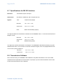
8.7 Specifications for RS 232 Interface
Baud rate:
Transmission speed: 1200 bps.
Data format:
One start bit, 8 data bits, and 2 stop bits are sent
Signals:
TXD -
Transmit Data (output)
Idle level
-3V >> U >> -7.5V
Active level
+3V << U << +7.5V
DTR -
Data Terminal Ready (output)
This signal indicates the transmission readiness of the OSMOMAT 050, i.e. it becomes active before a
telegram is sent.
Idle level
-3V >> U >> -7.5V
Active level
+3V << U << +7.5V
DSR -
Dataset Ready (input)
This signal can prevent transmission of a telegram. The OSMOMAT 050 starts transmitting only after
DSR becomes active. The user does not need to activate this signal, since it is equipped with an internal 15 k-Ohm 'pull-up' resistance.
Idle level
-3V >> U >> -15V
Active level
+3V << U << +15V
8.8 Transmission Software
We recommend using our TERMINAL SOFTWARE for easy data transmission to a PC and a data
acquisition that is optimized for the osmometer. In principle, any other terminal software can be used,
but the data format will have to be adjusted.
Version 1.1 (2011-10-12)
OSMOMAT 050 User Guide
Page 41 of 51
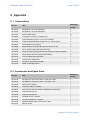
9 Appendix
9.1 Consumables
Packaging
Item no.
Item
50.9.0010
Membranes, cut-off 10,000 dalton
5
50.9.0020
Membranes, cut-off 20,000 dalton
5
50.9.0030
Silicon rubber septa
10
50.9.0040
O ring (26 x 2 mm) for measuring cell
5
50.9.0050
Connecting tube (Tygon 1.12 m, 0.04" internal)
1
50.9.0060
Tubes for peristaltic pump (Tygon 9.5 cm, 3/32" internal)
5
50.9.0070
Tube nipples for tube pump
2
50.9.0080
Plastic tuberculin syringe with special cannula 16 mm
2
50.9.0090
30 mL plastic syringe with tube and clamp
1
50.9.0100
250 µL precision syringe with special cannula for septum injection
1
50.9.0130
Plastic bottles 250 mL (supply/waste bottles)
2
50.9.0140
Tool for widening the tube ends
1
50.9.0150
Tweezers for membranes
1
50.9.0160
Plunger for supply/waste bottles
2
50.9.0180
Bottle of cleaning solution
1
unit/qty
9.2 Accessories and Spare Parts
Packaging
Item no.
Item
00.9.0102
Package with 10 fine-wire fuses, 0,25A slow, 220V
1
00.9.0104
Package with 10 fine-wire fuses, 0,5A slow, 110V
1
20.9.0100
Power cord, 2 meters
1
20.9.0120
Connector cable for recorder
1
20.9.0160
Data cable for RS 232 interface OSMOMAT 030/050/010
1
50.2.0020
Lower measuring cell
1
50.2.0030
Upper measuring cell
1
50.2.0040
Peristaltic pump, complete
1
50.3.0010
Pressure transducer, complete
1
50.5.0030
Mainboard (050-KOP/1), from series 1990
1
50.9.0170
Septum screw
1
unit/qty
Version 1.1 (2011-10-12)
Page 42 of 51
OSMOMAT 050 User Guide
9.3 Classification of the IVD
®
The Gonotec OSMOMAT 050 colloid osmometer is a non-invasive in-vitro diagnostic product accord®
ing to EEC Directive 93/42 (Medical Devices Law). The OSMOMAT 050 colloid osmometer is not
named in Annex II, list A or B, of the Directive 98/79/EEC for in-vitro diagnostics. Compliance is declared per Annex III. Number 6 of Annex II is disregarded, since the unit’s intended use does not include personal use.
9.4 EC Compliance Statement - OSMOMAT® 050
Gonotec GmbH
GSG-Hof Reuchlinstr. 10-11
D-10553 Berlin
®
We hereby declare that the OSMOMAT 050 colloid osmometer complies with Directive 98/79/EEC.
Compliance is declared per Annex III of the Directive. The CE mark on the unit acknowledges this.
Date:
Signature of managing director:
9.5 Provisions of Certification
CE compliance requires that the unit is installed and operated in the manner described in this manual.
Any departure from the specifications or independent modifications of the unit without the express
consent of Gonotec GmbH may result in a violation of CE requirements. Such actions invalidate the
compliance statement and transfer responsibility to the originator of said actions.
Version 1.1 (2011-10-12)
OSMOMAT 050 User Guide
Page 43 of 51
10 Limited Warranty
Gonotec product
Duration of Limited Warranty
C.
Limitations of Liability
Software 90 days
To the extent permissible under the applicable local laws, the
Pressure transducer 180 days
legal remedies named here shall be the sole and exclusive
Osmometer
2 years
legal remedies available to the customer.
TO THE EXTENT PERMISSIBLE UNDER THE APPLICABLE
A.
Extension of the Limited Warranty
LOCAL LAWS AND WITH THE EXCEPTION OF THE OBLI-
Gonotec warrants the end user that Gonotec products shall be
GATIONS EXPRESSLY NAMED HERE, NEITHER
free from manufacturing and material defects for the above
GONOTEC NOR ITS SUPPLIERS SHALL BE LIABLE FOR
periods of validity from the purchase date. The end user must
DIRECT OR INDIRECT, SPECIFIC, INCIDENTAL OR CON-
provide proof of the purchase date.
SEQUENTIAL LOSSES, WHETHER BASED ON A CON-
For software products, Gonotec’s limited warranty applies only
TRACT, A TORTIOUS ACT OR ANOTHER LEGAL THEORY,
to the non-execution of programming instructions. Gonotec
AND NOTWITHSTANDING PRIOR NOTIFICATION OF THE
does not guarantee that the operation of a product will proceed
POSSIBILITY OF SUCH A LOSS.
without errors or interruptions.
Respective Jurisdiction
Gonotec’s limited warranty applies only to defects that arise
This warranty statement guarantees the customer certain legal
during normal operation of the product. It does not apply under
claims. The customer may have other legal claims that go
the following conditions:
beyond ttube outlined here. Such claims vary by state in the
Inadequate servicing or improper modification;
US, by province in Canada and by nation elsewhere in the
Use of software, interfaces, print media or accessories not
world.
supported or supplied by Gonotec; or
Elements of this warranty statement that conflict with local
Use of the equipment in a manner not covered by the product
laws can be regarded as amended to comply with the applica-
specifications.
ble laws. For this reason, certain warranty exclusions and
If Gonotec is notified within the warranty period of a defect in a
restrictions outlined here may be of no relevance to the cus-
software product, in media or in the pressure transducer and if
tomer. In some states of the US, in some Canadian provinces
the Gonotec warranty applies to the defect, Gonotec shall
and in some countries outside North America, for example, the
replace the defective product. If Gonotec is notified within the
following national laws apply:
warranty period of a defect in a hardware product and if the
Exclusion of the fact that the warranty exclusions and re-
Gonotec warranty applies to the defect, Gonotec shall repair or
strictions named here restrict the legal rights of a customer (for
replace the defective product at its discretion.
example: Great Britain)
If Gonotec is unable to repair or replace a defective product to
Restriction of the possibilities for manufacturers to enforce
which the Gonotec warranty applies, Gonotec shall refund the
such warranty exclusions and restrictions
purchase price of the product within a reasonable period
Granting of additional warranty claims for the customer, fixing
following notification of the respective defect.
of the validity period for implied warranty services that the
Gonotec is not obligated to repair or replace a product or
manufacturer may not exclude, or non-admission of re-
refund its purchase price until the customer returns the defec-
strictions relating to the validity period for implied warranty
tive product
services
to Gonotec.
THE FOLLOWING APPLIES TO CONSUMER TRANSAC-
Replacement products may be new or almost new, as long as
TIONS IN AUSTRALIA AND NEW ZEALAND: THE CONDI-
their functionality is at least that of the replaced product.
TIONS OF THIS WARRANTY STATEMENT NEITHER EX-
The Gonotec limited warranty is applicable in all countries in
CLUDE LEGAL RIGHTS APPLICABLE TO THE SALE OF
which Gonotec sells the applicable product. The following
GONOTEC PRODUCTS TO SUCH CUSTOMERS NOR
countries and regions are exceptions: All countries outside the
REPRESENT A RESTRICTION OR AMENDMENT OF SUCH
EU. In these countries, the warranty is only valid in the country
RIGHTS, BUT INSTEAD REPRESENT A SUPPLEMENT TO
in which the product was purchased. Contracts for additional
THESE RIGHTS, EXCEPT TO THE EXTENT PERMISSIBLE
warranty services, such as on-site service, may be available
UNDER THE LAW.
from an authorized Gonotec sales partner.
B.
Limitation of the Warranty
TO THE EXTENT PERMISSIBLE UNDER THE APPLICABLE
LOCAL LAWS, NEITHER GONOTEC NOR ITS SUPPLIERS
SHALL ASSUME ANY ADDITIONAL WARRANTY SERVICES
OR ACCEPT ANY OTHER CONDITIONS, EXPRESS OR
IMPLIED, WITH REGARD TO THE GONOTEC PRODUCTS.
Version 1.1 (2011-10-12)
Seite 44 von 51
Handbuch OSMOMAT 050
11 Returning Parts for Warranty
11.1 Repair or Credit
All products returned for repair or credit must be prepared as follows:
1. Call or write to request a free return order for equipment that is being returned for warranty repair or credit.You may also request a return order for equipment that is being returned for nonwarranty repair, but you will be liable for the cost of the return order.
2. Clean and disinfect the equipment before returning it to us. We will charge a processing fee for cleaning and disinfecting contaminated equipment. Equipment that is
strongly contaminated will be returned at the customer’s expense.
3. Enclose written information explaining the reason for returning the equipment.
4. If the equipment is being returned for credit, you must include all accessories (power cord,
software disks, manuals, etc.).
5. Return the equipment in its original packaging. If you no longer have the original packaging,
you may purchase replacement packaging from Gonotec.
11.2 Before Calling Gonotec
Note: When calling Gonotec, have your unit’s serial number ready. The serial number helps our service technicians to more quickly record the unit and determine a procedure.
If possible, switch on the unit before calling Gonotec’s technical service. Use a telephone that is close
to the unit. You may be asked to provide detailed information while running operations or apply other
troubleshooting methods that can only be performed on the unit itself. Ensure that you have the
equipment documentation handy.
Warning: Before undertaking any work on the equipment, read the safety notices in the appropriate chapters of this manual.
Version 1.1 (2011-10-12)
Handbuch OSMOMAT 050
Seite 45 von 51
12 Specifications of the OSMOMAT 050
Cell volume:
< 10 µL
Sample volume:
> 100 µL
Adding sample:
by injection syringe through a septum injector integrated
into the measuring cell
Membrane material:
Two-layer membrane, retention of molecular weights
> 10,000 – 30,000 dalton depending on type
Zero point setting:
automatic
Measurement time:
< 1 minute up to approx. 3 minutes depending on
membrane type
Measuring range:
73 mm HG, 100 cm H2O column, or 9.99 k-Pascal
Reproducibility:
< ± 0.5 mm HG
Calibration:
direct pressure calibration through hydrostatic solvent column or using solutions of known concentration
Measurement display:
3-digit
Recorder output:
2 mV/digit, adjustable ± 10%, for strip chart recorder with
1 Volt maximum deflection
Automation:
1. Automatic rinsing of the upper half of the cell to
maintain measurement readiness using the built-in
tube pump
2. Storage of measurement results
3. Storage of an additional measurement value following a specific delay after obtaining the first
measurement result
Data output:
RS 232 C
Power connection:
230V (±10%), 50-60 Hz, 20 VA
Special versions 115V or 100V available
Dimensions and Weight:
Width 36 cm
Height 25 cm
Depth 35.5 cm
5.1 kg excluding bottles
Subject to technical changes
Version 1.1 (2011-10-12)
Seite 46 von 51
Handbuch OSMOMAT 050
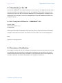
13 Service Instructions for Replacing a Defective
Pressure Transducer
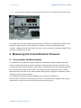
13.1 When is a replacement of the pressure transducer required?
The pressure transducer must be replaced in the following cases:
1. The OSMOMAT 050 no longer switches to STAND BY mode
2. A continuous alarm sounds, even when the measuring cell is open
3. The solvent added to the opened measuring cell flows downward through the pressure
transducer
The pressure transducer can be replaced by trained medical technicians by following these instructions.
A new pressure transducer can be ordered using order no. 50.3.0010. The serial number of your device must be communicated because devices up to serial number 101122 also require replacement of
the lower measuring cell due to a component change by the manufacturer of the sensor.
Package contents:
•
1 pressure transducer, complete with board and cable
•
1 O ring
•
1 cable tie
Version 1.1 (2011-10-12)
Handbuch OSMOMAT 050
Seite 47 von 51
13.2 Instructions
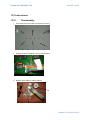
13.2.1
Disassembly
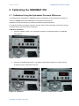
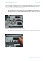
1. Unscrew and remove lower front panel (6 screws).
2. Unplug pressure transducer connector from board.
3. Release LED cable by cutting cable tie.
Version 1.1 (2011-10-12)
Seite 48 von 51
Handbuch OSMOMAT 050
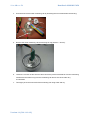
4. Unscrew and remove lower measuring cell by loosening the two screws below the housing.
5. Remove the lower measuring cell and the large O ring (63.22 x 1.78 mm).
6. Loosen the counter nut and unscrew and remove the pressure transducer from the measuring
cell.Remove the small O ring from the measuring cell and do not reuse under any
circumstanes
7. Thoroughly rinse the lower half of the measuring cell using water and dry.
Version 1.1 (2011-10-12)
Handbuch OSMOMAT 050
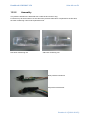
13.2.2
Seite 49 von 51
Assembly
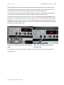
The pressure transducer is delivered with a cable tie and a new O ring.
For devices up to serial number 101122 where the pressure transducer is replaced for the first time,
the lower measuring cell must be replaced as well.
New lower measuring cell
Old lower measuring cell
New pressure transducer
Old pressure transducer
Version 1.1 (2011-10-12)
Seite 50 von 51
Handbuch OSMOMAT 050
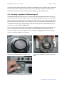
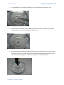
1. If you already have a new lower measuring cell, you have to remove the old O- ring.
2. Clean the lower measuring cell with cleaning solution and rinse it with water very carefully.
Install the new O ring (2 mm) in the lower measuring cell.
3. Screw the pressure transducer into the lower half of the measuring cell. It may be necessary
to back off the counter nut a bit. Screw in the pressure transducer with moderate force until
the O ring is pressed against the cell and the ring becomes visibly deep dark.
Version 1.1 (2011-10-12)
Handbuch OSMOMAT 050
Seite 51 von 51
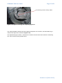
4. Screw the counter nut against the measuring cell to secure the system.
5. Assembly of the lower measuring cell
Replace the large O ring (63.22 x 1.78 mm) in the lower half of the cell and reinstall the cell
half into the housing from below using the two screws.
Insert the yellow LED into the designated bore and secure using cable tie.
Plug the connector of the pressure transducer into the mainboard and replace the lower housing cover using the six screws.
The OSMOMAT 050 is ready for use again.
Version 1.1 (2011-10-12)