1
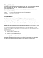
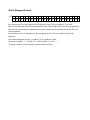
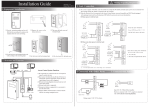
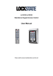
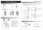
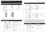
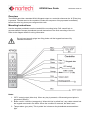
KPW26 User Guide DOC0074 Issue 02 Overview The KPW26 provides a standard 26-bit Wiegand output to a controller whenever the ‘#’ (Enter) key is pressed. The data sent to the controller includes the sequence of keys pressed immediately before the enter key plus a pre-configured site code. Mounting Instructions Use the template provided to mark out and drill the mounting holes. Drill a small hole to accommodate the tamper photodiode to avoid obstruction to the flush mounting of the unit. Refer to the diagram below for wiring information. Do not insert security plugs into fixing holes until the keypad has been fully installed and tested. Notes: 1. CCTV control output (blue wire). When any key is pressed, a 30-second ground pulse is generated (250mA). 2. Buffer control / Hold line (orange wire). When this line is pulled ‘low’, any codes entered into the keypad are stored in the buffer. When the condition is removed, the data is sent. 3. Tamper alarm (grey wire). This is pulled ‘low’ whenever the photodiode senses ambient light. Setting the Site Code The KPW26 is factory programmed with the default site code “000”. This site code can be changed to any value between “000” and “255”. To change the value, follow the example below: To set the site code to “100” Disconnect the power supply for at least 10 seconds. Within 3 seconds of reconnection of the power supply, do the following: Enter - the keypad enters programming mode (LED flashes amber). Enter100# - site code 100 is assigned. Using the KPW26 In the quiescent state the LED on the KPW26 glows red (Brown wire not pulled ‘low’). To enter a code, enter any number below 65,535 followed by a ‘#’ (enter) key (note that the maximum number may be further limited by the controller – refer to the User Manual for the controller). With each key press, the LED flashes amber and the buzzer sounds. Once the enter key has been pressed, the sequence of keys pressed immediately before it are sent to the controller as the ‘card number’ in a 26-bit Wiegand format with the pre-configured ‘site code’. When the LED control input (brown wire) is pulled ‘low’ by the controller, the LED changes to green (the LED control input is pulled to the internal +5V via a 2.2 Kohm resistor). If an invalid key combination is entered, the KPW26 sends an error code (all binary 1’s) to the controller (this may appear as card number 65535 at the controller). The LED flashes amber twice to indicate the error. Invalid key combinations are: Pressing ‘#’ with no preceding digits Including ‘’ in the number preceding ‘#’ Pressing only 0’s before pressing ‘#’ Entering 65535 or any number above it before pressing ‘#’ All other key combinations entered followed by ‘#’ will be sent to the controller as a ‘card number’. It is then up to the controller to determine whether or not it represents a valid user code. 26-bit Wiegand Format BIT 1 2 9 10 25 26 P S S S S S S S S N N N N N N N N N N N N N N N N P Bit 1 (shown as ‘P’) is even parity for the following 12 bits. The sum of bits 1-13 is even. Bits 2 to 9 (shown as ‘S’) are the programmable ‘Site Code’ (000 to 255). Bit 2 is most significant. Bits 10 to 25 (shown as ‘N’) represent the number entered prior to pressing ‘#’ (Enter). Bit 10 is most significant. Bit 26 (shown as ‘P’) is odd parity for the preceding 12 bits. The sum of bits 14-26 is odd. Example: Site Code configured to “004”. A code of “123” is entered (123#). Output to controller: 1 0 0 0 0 0 1 0 0 0 0 0 0 0 0 0 0 0 1 1 1 1 0 1 1 1 The data is sent at 1ms per bit with a pulse duration of 50s KPW26 Drilling Template 180 146