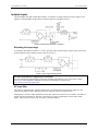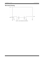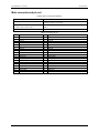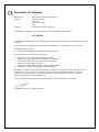
1
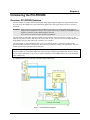
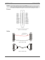
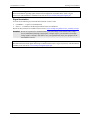
PCI-PDISO8 Isolated Input and Relay Output User's Guide Document Revision 10 April 2012 © Copyright 2012 Your new Measurement Computing product comes with a fantastic extra — Management committed to your satisfaction! Thank you for choosing a Measurement Computing product—and congratulations! You own the finest, and you can now enjoy the protection of the most comprehensive warranties and unmatched phone tech support. It’s the embodiment of our mission: To provide data acquisition hardware and software that will save time and save money. Simple installations minimize the time between setting up your system and actually making measurements. We offer quick and simple access to outstanding live FREE technical support to help integrate MCC products into a DAQ system. Limited Lifetime Warranty: Most MCC products are covered by a limited lifetime warranty against defects in materials or workmanship for the life of the product, to the original purchaser, unless otherwise noted. Any products found to be defective in material or workmanship will be repaired, replaced with same or similar device, or refunded at MCC’s discretion. For specific information, please refer to the terms and conditions of sale. Harsh Environment Program: Any Measurement Computing product that is damaged due to misuse, or any reason, may be eligible for replacement with the same or similar device for 50% of the current list price. I/O boards face some harsh environments, some harsher than the boards are designed to withstand. Contact MCC to determine your product’s eligibility for this program. 30 Day Money-Back Guarantee: Any Measurement Computing Corporation product may be returned within 30 days of purchase for a full refund of the price paid for the product being returned. If you are not satisfied, or chose the wrong product by mistake, you do not have to keep it. These warranties are in lieu of all other warranties, expressed or implied, including any implied warranty of merchantability or fitness for a particular application. The remedies provided herein are the buyer’s sole and exclusive remedies. Neither Measurement Computing Corporation, nor its employees shall be liable for any direct or indirect, special, incidental or consequential damage arising from the use of its products, even if Measurement Computing Corporation has been notified in advance of the possibility of such damages. Trademark and Copyright Information Measurement Computing Corporation, InstaCal, Universal Library, and the Measurement Computing logo are either trademarks or registered trademarks of Measurement Computing Corporation. Refer to the Copyrights & Trademarks section on mccdaq.com/legal for more information about Measurement Computing trademarks. Other product and company names mentioned herein are trademarks or trade names of their respective companies. © 2012 Measurement Computing Corporation. All rights reserved. No part of this publication may be reproduced, stored in a retrieval system, or transmitted, in any form by any means, electronic, mechanical, by photocopying, recording, or otherwise without the prior written permission of Measurement Computing Corporation. Notice Measurement Computing Corporation does not authorize any Measurement Computing Corporation product for use in life support systems and/or devices without prior written consent from Measurement Computing Corporation. Life support devices/systems are devices or systems that, a) are intended for surgical implantation into the body, or b) support or sustain life and whose failure to perform can be reasonably expected to result in injury. Measurement Computing Corporation products are not designed with the components required, and are not subject to the testing required to ensure a level of reliability suitable for the treatment and diagnosis of people. HM PCI-PDISO8.docx Table of Contents Preface About this User's Guide ....................................................................................................................... 4 What you will learn from this user's guide ......................................................................................................... 4 Conventions in this user's guide ......................................................................................................................... 4 Where to find more information ......................................................................................................................... 4 Register-level programming ............................................................................................................................................. 4 Chapter 1 Introducing the PCI-PDISO8................................................................................................................. 5 Overview: PCI-PDISO8 features ........................................................................................................................ 5 Chapter 2 Installing the PCI-PDISO8..................................................................................................................... 6 What comes with your PCI-PDISO8 shipment? ................................................................................................. 6 Hardware .......................................................................................................................................................................... 6 Software ............................................................................................................................................................................ 6 Documentation .................................................................................................................................................................. 6 Optional components ........................................................................................................................................................ 6 Unpacking........................................................................................................................................................... 6 Installing the software ........................................................................................................................................ 6 Installing the hardware ....................................................................................................................................... 6 Signal connections .............................................................................................................................................. 7 P2 pinout ........................................................................................................................................................................... 8 Cabling.............................................................................................................................................................................. 8 Signal termination ............................................................................................................................................................. 9 Chapter 3 Functional Details ...............................................................................................................................10 Relay outputs .................................................................................................................................................... 10 Form C relay ....................................................................................................................................................................10 Form A relay ....................................................................................................................................................................10 Isolated inputs ................................................................................................................................................... 11 Extending the input range ................................................................................................................................................11 AC input filter ..................................................................................................................................................................11 Mechanical drawing ......................................................................................................................................... 12 Chapter 4 Specifications ......................................................................................................................................13 Isolated inputs ................................................................................................................................................... 13 Power consumption .......................................................................................................................................... 13 Environmental .................................................................................................................................................. 13 Main connector and pin out .............................................................................................................................. 14 Declaration of Conformity ..................................................................................................................15 3 Preface About this User's Guide What you will learn from this user's guide This user's guide describes the Measurement Computing PCI-PDISO8 data acquisition device and lists device specifications. Conventions in this user's guide For more information Text presented in a box signifies additional information and helpful hints related to the subject matter you are reading. Caution! Shaded caution statements present information to help you avoid injuring yourself and others, damaging your hardware, or losing your data. bold text Bold text is used for the names of objects on a screen, such as buttons, text boxes, and check boxes. italic text Italic text is used for the names of manuals and help topic titles, and to emphasize a word or phrase. Where to find more information Additional information about the PCI-PDISO8 is available on our website at www.mccdaq.com. You can also contact Measurement Computing Corporation by phone, fax, or email with specific questions. Phone: 508-946-5100 and follow the instructions for reaching Tech Support Fax: 508-946-9500 to the attention of Tech Support Email: [email protected] Register-level programming You should use the Universal Library to control your board. Only experienced programmers should attempt register-level programming. If you need to program at the register level in your application, refer to the Register Map for the PCI-PDISO8. This document is available on our web site at www.mccdaq.com/registermaps/RegMapPCI-PDISO8.pdf. 4 Chapter 1 Introducing the PCI-PDISO8 Overview: PCI-PDISO8 features The PCI-PDISO8 is an eight channel-isolated high voltage digital input and eight relay output interface board. You can use the PCI-PDISO8 for control and sensing applications where high voltages need to be sensed or controlled. Caution! High voltages are present on the PCI-PDISO8 board when you connect high voltage inputs or outputs to the PCI-PDISO8 connector. Use extreme caution! Never handle the PCI-PDISO8 when signals are connected to the board through the connector. Never remove the protective plates from the PCI-PDISO8. The eight inputs are individual, optically-isolated (500 V) inputs that can be read back as a single byte. The inputs are not polarity sensitive and may be driven by either AC (50 - 1000 Hz) or DC. Each input channel has a programmable low-pass filter with a time constant of 5 ms (200 Hz). The eight outputs are electromechanical relays. Five relays provide Form C connections, and three relays provide normally-open Form A connections. The relays are controlled by writing to an eight-bit port. The relay control register can be read back from the same port. Signal conditioning installed The PCI-PDISO8 is a combination digital I/O board with signal conditioning installed. Most accessory boards provide signal conditioning or easy-to-access signal termination. The PCI-PDISO8 does not require additional signal conditioning. PCI-PDISO8 functions are illustrated in the block diagram shown here. Figure 1. PCI-PDISO8 block diagram 5 Chapter 2 Installing the PCI-PDISO8 What comes with your PCI-PDISO8 shipment? The following items are shipped with the PCI-PDISO8. Hardware PCI-PDISO8 Software MCC DAQ CD Documentation In addition to this hardware user's guide, you should also receive the Quick Start Guide. This booklet provides an overview of the MCC DAQ software you received with the device, and includes information about installing the software. Please read this booklet completely before installing any software or hardware. Optional components Cables o C37FF-x and C37FFS-x Signal termination boards Measurement Computing provides signal termination boards for use with the PCI-PDISO8. Refer to Signal termination on page 9 for more information. Unpacking As with any electronic device, you should take care while handling to avoid damage from static electricity. Before removing the PCI-PDISO8 from its packaging, ground yourself using a wrist strap or by simply touching the computer chassis or other grounded object to eliminate any stored static charge. If any components are missing or damaged, notify Measurement Computing Corporation immediately by phone, fax, or e-mail: Phone: 508-946-5100 and follow the instructions for reaching Tech Support Fax: 508-946-9500 to the attention of Tech Support Email: [email protected] For international customers, contact your local distributor. Refer to the International Distributors section on our web site at www.mccdaq.com/International. Installing the software Refer to the Quick Start Guide for instructions on installing the software on the MCC DAQ CD. This booklet is available in PDF at www.mccdaq.com/PDFmanuals/DAQ-Software-Quick-Start.pdf. Installing the hardware The PCI-PDISO8 is completely plug-and-play. There are no switches or jumpers to set. Configuration is controlled by the system BIOS. 6 PCI-PDISO8 User's Guide Installing the PCI-PDISO8 Install the MCC DAQ software before you install your board The driver needed to run your board is installed with the MCC DAQ software. Therefore, you need to install the MCC DAQ software before you install your board. Refer to the Quick Start Guide for instructions on installing the software. Complete the following steps to install the board: 1. Turn your computer off, open it up, and insert your board into an available PCI slot. 2. Close your computer and turn it on. When you connect the device for the first time to a computer running Windows, a Found New Hardware dialog opens when the operating system detects the device. If the information file for this board is not already loaded onto your PC, you will be prompted for the disk containing this file. The MCC DAQ software contains this file. If required, insert the Measurement Computing Data Acquisition Software CD and click OK. 3. To test your installation and configure your board, run the InstaCal utility installed in the previous section. Refer to the Quick Start Guide that came with your board for information on how to initially set up and load InstaCal. Signal connections The table below lists the board connectors, applicable cables and compatible accessory boards. Board connectors, cables, accessory equipment I/O connector type Compatible cable Compatible accessory products (with the C37FFS-x and C37FF-x cables) P2: 37-pin D connector C37FF-x, where x = length in feet C37FFS-x, where x =5 or 10 feet CIO-MINI37 SCB-37 Figure 2 shows the location of the I/O connector P2 and board relays. Figure 2. P2 connector and relays (shown with protective cover removed) The board is shipped with a protective plate covering some components. The board in Figure 2 is shown with the protective cover removed – we recommend that the cover always be left in place during use. 7 PCI-PDISO8 User's Guide Installing the PCI-PDISO8 Caution! Do not remove the protective plate on the PCI-PDISO8. High voltages are present on the board when you connect high voltage inputs or outputs to the board connector. Use extreme caution! Never handle the PCI-PDISO8 when signals are connected to the board through the connector. P2 pinout Figure 3. P2 connector pinout Cabling The red stripe identifies pin # 1 1 1 20 20 37 37 19 19 Figure 4. C37FF-x cable 1 19 20 37 20 19 1 Figure 5. C37FFS-x cable 8 37 PCI-PDISO8 User's Guide Installing the PCI-PDISO8 Information on signal connections General information regarding signal connection and configuration is available in the Guide to Signal Connections. This document is available on our web site at www.mccdaq.com/signals/signals.pdf. Signal termination You can use the following screw terminal board with the C37FF-x cable: CIO-MINI37 – 37-pin screw terminal board. SCB-37 – 37-conductor, shielded signal connection/screw terminal box. Details on these products are available on our web site at www.mccdaq.com/products/screw_terminal_bnc.aspx. Caution! Do not use exposed-screw terminal boards if your field voltage is more than 24 volts. Using a screw terminal board with high voltage inputs or outputs exposes you and others to those high voltage signals. Construct a safe cable to carry your signals directly from your equipment to the PCI-PDISO8 connector. Additional information about digital interfacing Detailed information about digital interfacing is contained in the Guide to Signal Connections. This document is available on our web site at www.mccdaq.com/signals/signals.pdf. 9 Chapter 3 Functional Details Relay outputs Form C relay The Form C relay has a common, normally open (NO) and normally closed (NC) contact. Figure 6 shows the schematic for a Form C relay, like those connected at relay 0 through relay 4. Figure 6. Form C Relay (0) contacts When 0 is written to the output, the common and NC are in contact. When 1 is written to the output, the common and NO are in contact. Form A relay The Form A relay has a common and a normally open (NO) contact. Figure 7 shows the schematic for a Form A relay, like those connected at relay 5 through relay 7. Figure 7. Form A Relay (5) contacts When 0 is written to the output, the common and NO are NOT in contact. When 1 is written to the output, the common and NO are in contact. The Form A and Form C relays on the PCI-PDISO8 board are the same type. Only the connections to the relay poles differ. 10 PCI-PDISO8 User's Guide Functional Details Isolated inputs The PCI-PDISO8 has eight isolated input channels. A schematic of a single channel is shown in Figure 8. The signals are routed through a bridge rectifier so that the inputs are not polarity sensitive. Figure 8. Isolated input schematic - simplified Extending the input range To extend the input range beyond the 5 V to 28 V specified, add an external resistor. Figure 9 shows the resistor and the equations used to calculate resistor values for a given Vin. Figure 9. Input range-extending resistor For more information on digital signal connections For more information on digital signal connections and digital I/O techniques, refer to the Guide to Signal Connections. This document is available on our web site at available on our web site at www.mccdaq.com/signals/signals.pdf). AC input filter The inputs are eight individual, optically isolated (500 V) inputs that can be read back as a single byte. The inputs are not polarity sensitive and may be driven by either AC (50 Hz to 1000 Hz) or DC. Each input has a software enabled/disabled low-pass filter with a time constant of 5 ms (200 Hz). You enable or disable each input with InstaCal. The filter is required for AC inputs, and should be used for almost all DC inputs. Unless you have reason to turn off a filter, you should enable it. 11 PCI-PDISO8 User's Guide Functional Details Mechanical drawing Figure 10. PCI-PDISO8 board dimensions 12 Chapter 4 Specifications Typical for 25°C unless otherwise specified. Specifications in italic text are guaranteed by design. Relay specifications Table 1. Relay specifications Number Contact configuration Contact rating Contact resistance Operate time Release time Vibration Shock Dielectric isolation Life expectancy Power on RESET state 8 5 FORM C (SPDT) RELAY 0 through RELAY 4 3 FORM A (SPST) RELAY 5 through RELAY 7 6 A @ 120 VAC or 28 VDC resistive (see connector rating below) 100 milliohms max 20 milliseconds max 10 milliseconds max 10 to 55 Hz (Dual amplitude 1.5 mm) 10 G (11 milliseconds) 500 V (1 minute) 10 million mechanical operations, min Not energized. NC in contact to Common. Isolated inputs Table 2. Isolated input specifications Number Isolation Resistance Voltage range Input ‘High’ level Input ‘Low’ level Response Filters 8 500 V 1.6 k Ohms min. DC: 5 to 28 V (Not TTL compatible) AC: 5 to 28 V (50 to 1000 Hz) >5V min (positive or negative input voltage - not TTL compatible) <2.5V max (positive or negative input voltage) w/o filter: 20 µS w/filter: 5 mS Time constant: 5 mS (200 Hz) Filter control: Software programmable at each input Power-up /reset: Filters off Power consumption Table 3. Power consumption specifications +5 V Power All relays off: All relays on: 0.4 A typical 1 A typical Environmental Table 4. Environmental specifications Operating temperature range Storage temperature range Humidity 0 to 70 °C -40 to 100 °C 0 to 90% non-condensing 13 PCI-PDISO8 User's Guide Specifications Main connector and pin out Table 5. Main connector specifications I/O connector type Compatible cable Compatible accessory products (with the C37FFS-x and C37FF-x cables) Max current 37-pin D connector C37FF-x, where x = length in feet C37FFS-x, where x =5 or 10 feet CIO-MINI37 SCB-37 5A Table 6. Connector pin out Pin 1 2 3 4 5 6 7 8 9 10 11 12 13 14 15 16 17 18 19 Signal Name Input 7A Input 6A Input 5A Input 4A Input 3A Input 2A Input 1A Input 0A Relay 7 (C) Relay 6 (C) Relay 5 (C) Relay 4 (NC) Relay 4 (NO) Relay 3 (C) Relay 2 (NC) Relay 2 (NO) Relay 1 (C) Relay 0 (NC) Relay 0 (NO) Pin 20 21 22 23 24 25 26 27 28 29 30 31 32 33 34 35 36 37 Signal Name Input 7B Input 6B Input 5B Input 4B Input 3B Input 2B Input 1B Input 0B Relay 7 (NO) Relay 6 (NO) Relay 5 (NO) Relay 4 (C) Relay 3 (NC) Relay 3 (NO) Relay 2 (C) Relay 1 (NC) Relay 1 (NO) Relay 0 (C) 14 Declaration of Conformity Manufacturer: Address: Category: Measurement Computing Corporation 10 Commerce Way Suite 1008 Norton, MA 02766 USA Information technology equipment. Measurement Computing Corporation declares under sole responsibility that the product PCI-PDISO8 to which this declaration relates is in conformity with the relevant provisions of the following standards or other documents: EC EMC Directive 2004/108/EC: Electromagnetic Compatibility, EN 61326-1:2006 (IEC 61326-1:2005) Emissions: Group 1, Class B EN55022 (1995)/CISPR 22: Radiated and Conducted emissions. Immunity: EN61326-1:2006, (IEC 61326-1:2005) EN61000-4-2 (2001): Electrostatic Discharge immunity. EN61000-4-3 (2002): Radiated Electromagnetic Field immunity. EN61000-4-4 (2004): Electric Fast Transient Burst immunity. EN61000-4-5 (2001): Surge immunity. EN61000-4-6 (2003): Radio Frequency Common Mode immunity. EN61000-4-11 (2004): Voltage Dip and Interrupt immunity. Declaration of Conformity based on tests conducted by Chomerics Test Services, Woburn, MA 01801, USA in September, 2001. Test records are outlined in Chomerics Test Report #EMI3053.01. Further testing was conducted by Chomerics Test Services, Woburn, MA. 01801, USA in December, 2008. Test records are outlined in Chomerics Test report #EMI5241.08. We hereby declare that the equipment specified conforms to the above Directives and Standards. Carl Haapaoja, Director of Quality Assurance Measurement Computing Corporation 10 Commerce Way Suite 1008 Norton, Massachusetts 02766 (508) 946-5100 Fax: (508) 946-9500 E-mail: [email protected] www.mccdaq.com