1
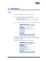
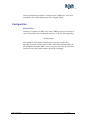
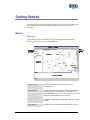
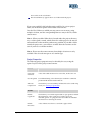
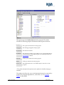
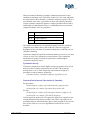
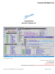
CARE
Computer-Aided Reengineering
Environment
User Guide
Version 2.0.2
August 2004
http://www.atxsoftware.com
CARE – Users Guide
Pág. 2 de 46
1.
INTRODUCTION ......................................................................................................................................... 6
2.
INSTALLATION .......................................................................................................................................... 7
SETUP ................................................................................................................................................................... 7
CONFIGURATION .................................................................................................................................................. 8
External files.................................................................................................................................................... 8
3.
FEATURES.................................................................................................................................................... 9
4.
GETTING STARTED................................................................................................................................. 11
BASICS ............................................................................................................................................................... 11
Work area ...................................................................................................................................................... 11
WORKING WITH PROJECTS ................................................................................................................................. 12
Project Properties ......................................................................................................................................... 13
VIEWING A PROGRAM ........................................................................................................................................ 14
Text Window .................................................................................................................................................. 14
Outline Browser ............................................................................................................................................ 15
SETUP OF THE PROJECT ....................................................................................................................................... 17
5.
REENGINEERING TECHNIQUES .......................................... ERROR! BOOKMARK NOT DEFINED.
6.
RT:TRANSFORMATIONS ....................................................................................................................... 19
TRANSFORMATIONS ........................................................................................................................................... 19
DEFINING TRANSFORMATIONS ........................................................................................................................... 20
What is a Marker ? ........................................................................................................................................ 20
How is the marking information relevant for the transformation process?................................................... 21
How does a marker work ?............................................................................................................................ 21
Creating Markers .......................................................................................................................................... 22
MARKING ENTRIES ............................................................................................................................................. 23
WHAT IS A TRANSFORMATION ?......................................................................................................................... 23
CREATING TRANSFORMATIONS .......................................................................................................................... 24
Used Patch Templates ................................................................................................................................... 25
Generic Patch Templates .............................................................................................................................. 25
WHAT IS A PATCH TEMPLATE ?.......................................................................................................................... 26
CREATING PATCH TEMPLATES ........................................................................................................................... 26
LOADING STORED DATA ..................................................................................................................................... 27
THE TRANSFORMATION PROCESS....................................................................................................................... 28
Marking ......................................................................................................................................................... 28
APPLYING TRANSFORMATIONS ........................................................................................................................... 29
GENERATING THE TRANSFORMED PROGRAM ...................................................................................................... 31
7.
RT: SLICING .............................................................................................................................................. 32
OVERVIEW ......................................................................................................................................................... 32
WORKING WITH SLICING .................................................................................................................................... 32
8.
METRICS .................................................................................................................................................... 36
INTRODUCTION TO METRICS ............................................................................................................................... 36
SIZE AND UNDERSTANDABILITY METRICS ......................................................................................................... 36
Line counts .................................................................................................................................................... 36
Lines of code (LOC, sLOC) ........................................................................................................................... 36
Comment lines ............................................................................................................................................... 37
COMPLEXITY METRICS....................................................................................................................................... 37
Cyclomatic complexity (McCabe) ................................................................................................................. 37
Cyclomatic density......................................................................................................................................... 38
Structural fan-in/fan-out (Constantine & Yourdon) ...................................................................................... 38
Informational fan-in/fan-out and informational complexity (Henry & Kafura) ............................................ 39
Halstead's Software Science Collection of Properties................................................................................... 39
Maintainability index..................................................................................................................................... 40
Depth of call tree ...........................................................................................................................................40
UNSTRUCTURABILITY METRICS .........................................................................................................................40
GoTo’s ...........................................................................................................................................................40
Dead Code .....................................................................................................................................................40
Nested conditionals........................................................................................................................................41
Nested loops...................................................................................................................................................41
CARE METRICS .................................................................................................................................................41
9.
ADVANCED FEATURES ..........................................................................................................................45
RULE LIBRARIES.................................................................................................................................................45
ANALYSIS DATA .................................................................................................................................................45
DOCUMENTATION SITE .......................................................................................................................................45
10.
BATCH TRANSFORMATIONS ...........................................................................................................43
11.
EXAMPLES .............................................................................................................................................46
CARE – Users Guide
Pág. 4 de 46
Pág. 5 de 46
CARE – Users Guide
1. Introduction
The CARE tool is an environment targeting the reengineering,
transformation and documentation of COBOL programs (*).
(...)
(*) CARE version 1.0 only works with COBOL programs. Future versions
will allow other languages, if the parsers of the language to the CARE
internal AST format are available
CARE – Users Guide
Pág. 6 de 46
2. Installation
Setup
The installation of CARE goes through the following steps:
1 – First you should choose the required installation type:
to perform an installation without a JVM and use one previously
installed on the computer or
to perform an installation including a JVM dedicated for CARE
2 – Execute the supplied setup file according to the chosen installation type.
3 – Supply the information required in the different installation steps.
When using an existing JVM, it is necessary to select one of them (it must
be a JVM 1.4.1 or superior).
Confirm the information and click on the ‘Install’ button.
Pág. 7 de 46
CARE – Users Guide
After the installation procedure is completed, the CARE tool is ready to be
launched by the corresponding entry in the Program Menu.
Configuration
External files
During the execution of CARE, when using COBOL projects, the location of
some external files may be prompted to the user with the following dialog
<dialog image>
You should select the folder containing the external executable files,
typically located in a folder named ‘extbin’ under the installation folder. If
the installation procedure didn’t create it, copy the files from the CD to that
location (or any other) and configure the dialog accordingly.
CARE – Users Guide
Pág. 8 de 46
3. Features
CARE is primarily an open reengineering environment, but is capable of
supporting other activities in the software process development (SPD). It
was created as an environment hosting several known re-engineering
techniques.
The architecture used is based on uniform representations enabling the
support of several programming languages, with little effort to integrate
new ones. CARE supplies several basic libraries for the reengineering
techniques, namely transformations, but promotes and supports the use of
user-defined elements incorporating project specific knowledge and
requirements.
The following activities of the SPD/SQA may use the support of CARE
•
Reengineering
•
Program/System Analysis
•
Documentation
•
Code Certification
Basic CARE features are
•
Pág. 9 de 46
Application of one or several Reengineering techniques to a
program, including
o
Transformation - A transformation is used to produce
massive changes in source programs, by applying changes
to (user) identified patterns of code based in structural
information or data/control flow information.
o
Slicing - Slicing a program is identifying and extracting the
relevant sub-program that satisfies some criteria. The result
of a slice is still a valid program.
o
Extraction - Extraction is a technique for automatically
extracting procedural elements from a program, creating its
interface (when necessary) and inserting the appropriate
call instructions in the original program
•
Generation of a documentation website for a set of programs.
•
Visualization of program information in textual/graphical way:
program structure, control flow, dependency graphs.
CARE – Users Guide
CARE – Users Guide
Pág. 10 de 46
Getting Started
This chapter presents the general aspects of the tool. The functionalities and
tasks required to set a project ready to apply transformations are also
described.
Basics
Work area
The work area of the tool includes the typical components existing on a
IDE. We present here the most important ones:
Menu / Toolbar
Explorer Board
Explorer Window
Editor Board
Pág. 11 de 46
CARE – Users Guide
Edit Window
Navigator
Output Window
!
Working with Projects
To work with a set of programs it is required to create a project, where all
the necessary relevant source files will be included. A project is a working
unit with specific customizations and definitions that are valid for the
operations performed on that project. It also allows batch and multiple file
processing, optimizing time and resources in longer operations.
Several projects maybe open simultaneously in CARE.
A project is defined for one of the programming languages available, and is
selected at project creation time. The project language cannot be changed.
Current version of CARE do not support multi-language projects.
Creating a project
Before creating a project in the tool, is a good idea to organize the
source files under a project tree. Create a directory in the disk for the
project that you want to create - <project_dir>.
Create a sub-directory of that one ( eg. '
programs'
) and put the
hierarchy of source files you want to work with inside.
If your sources use include files (copybooks), its also a good idea to
create a sub-directory under the project directory to hold these files
Choose File > New Project. Locate the <project_dir>. Choose a name
for the project with extension .tpr. Click on the New button.
The project explorer appears with an empty project. The project is
saved at creation time.
After creating a project you may add folders to your project. The folder and
all the files with a valid source file extension for the project’s language will
be added to the project hierarchy, recursively.
Adding/removing programs from a project
Choose Add Folder from the project context menu. Locate the directory to
CARE – Users Guide
Pág. 12 de 46
insert. Click on the Select button.
The selected directory appears know as a folder inside the project.
If you want to add all valid sub-directories and files for a given project
folder, use the Refresh option in that folder context menu.
Once the files/folders are added you may remove one or many, using
multiple selection, and the corresponding Remove entry in the file/folder
context menu
Note 1 : When you add a folder that is located under the project directory
tree, a relative path is stored, which allows the whole project to be moved
and transfered to other machine without any problem. If you add a folder
outside the project tree, you will have to make shure the locations are the
same if you move to another machine.
Note 2 : Please note that context menus for multiple selections are only
available if the selected concepts are of a similar type.
Project Properties
The following project properties may be edited by the user, using the
option Properties in the project context menu.
General
Source File
extensions
A list of the valid extensions for source files, in the form '
.xxx'
User Properties
User defined string values that may be used in the comments
produced with the file transformations
Xml Data
Compression
Check this if you want auxiliary xml data files to be stored in zip
mode ( see Auxiliar program data ).
Includes
Pág. 13 de 46
Include
Copybooks
Check this if you want the representation of programs to include
the information of the copybooks. If copybooks are not
included, queries on a program will not consider the included
information for retrieving the results.
Include
Directories
A list of directories where to search the copybook files.
CARE – Users Guide
Copybook
extensions
A list of the valid extensions for copybook files.
SetUp
Check the data that will be produced when a setup operation is
performed ( see Additional project/program operations).
Change Text
The text that will be inserted in the transformed files, signaling
the applied patches. The text may be different according to the
kind of patch.
In the text several variables may be used, as $variable$. A
variable may be a defined User Property or a default property.
Default properties are: LINE, END_LINE, RULE, TIME, DATE.
Documentation
Several layout properties of the Web Site documentation
generation, including some colors and an icon image.
<The properties description must be updated to the current version/project>
Viewing a Program
Text Window
To view a program click on the program in the project tree. A text window
appears with the program source.
CARE – Users Guide
Pág. 14 de 46
When the tool operates with a program, some extra information is loaded (
see Auxiliar program data ). However, this information is only loaded
when it is needed. A dialog appears to confirm the operation or when a
possible mismatch between the program source and the last time the
information was generated requires an update of the information ( see also
Project SetUp).
Please note that by default when a program is open, it is on read only mode.
To change the program source, the option Edit Mode in the text editor
context-menu should be used. These changes will cause an information
update in future operations.
Outline Browser
The text editor presents the source code of the program. For better
understanding and navigability on the program structure, the outline of the
program may be used, by using the option Tools > Program Outline.
Pág. 15 de 46
CARE – Users Guide
This option opens the Outline browser for the program. The outline
includes the following program information and navigation shortcuts:
Includes
The copybook instructions in the program
Paragraphs
The existing paragraphs of the program
Declarations The declared variables
Procedures
The existing procedures. A procedure is a set of paragraphs that are
excuted as a whole, thus behaving like an isolated logical unit. See
"
for details.
Performs
All the perform instructions in the program
Goto's
All the goto instructions in the program
Dead Code
The statements that are not reachable by the control flow of the
program
<The outline information description must be updated to the different laguages
available>
The outline also allows the access to information that may be expressed by
graphs, like paragraph dependencies, control flow, etc. See Program
Graphs for the details.
CARE – Users Guide
Pág. 16 de 46
Setup of the project
The setup activity for a project is the generation of all the required files that
enables the project to be ready to define and apply program
transformations. Since in large projects this task may take a few minutes,
we recommend it to be performed before using the other CARE techniques.
The description of all the files that can be generated will be explained later
in this manual. We present here the minimum information that has to be
available for transforming groups of files in a batch process. Please note
that for applying transformations on a single open file, this setup activity is
not required, since the required files are generated automatically or after
user confirmation.
Set up a project
With the one file/several files selected in the project view or the project itself,
choose the menu option Process>Setup Auxiliary Files.
A dialog is open requiring the selection of which files to create: AST (program
structure) , CFA/DFA (Control/Data flow). Select both, or at least the AST
option.
The files that are not yet created or up-to-date are created while a progress
window displays the file being processed.
Choose now the menu option Process>Create Analysis Files.
A dialog is open requiring the selection of which files to create. Select only the
Interface option. Files are generated in a way similar to
Pág. 17 de 46
CARE – Users Guide
CARE – Users Guide
Pág. 18 de 46
4. Transformations - Definition
Transformations
Transformation is basically a process that performs modifications in
programs. This process relies on the identification of code/structure
patterns in the source program and the production of related modifications
into the transformed program.
When working with transformations, the CARE environment may be used
by two different groups of users:
•
!
#
!
$
$
#
•
!
$
!
!
$
%
Transformation is a technique for transforming a program based in 3
simple concepts: Markers, Transformations and Patches / Patch Templates. In
order to execute a transformation process a set of transformation
definitions has to be configured in a project.
Pág. 19 de 46
CARE – Users Guide
The picture shows a general view of the transformation process and the
data and activities involved. The following sections describe in detail the
definition and application of transformations.
Defining Transformations
A transformation definition includes:
•
one or several markers, that allows to identify patterns in the
program where transformations will occur.
•
a transformation, mapping the result of the markers to patches, that
can be instances of more generic patch templates
•
a patch template, that is a parametric change of the original
program.
What is a Marker ?
A marker identifies patterns in the program structure and gives as result a
set of markings. A marking includes one or more labelled entries which
represent program structure nodes or simple data like a string or a number.
A program node is an entity of the program to which is associated
Example: A marker VAR_12 that identifies all the declarations of variables
of size 12 may retrieve the following result
CARE – Users Guide
Pág. 20 de 46
Var_12 results
DecInst
VarName
Format
(line 43:10-37)
'
NUM-REG'
'
X(12)'
(line 45:14-38)
'
NUM-CONT'
'
9(12)'
Two markings were found, one for the instruction in line 43 and other in
line 45, with the corresponding variable name and format entries.
<code>
How is the marking information relevant for the transformation
process?
The entries that represent program nodes are valid anchors to produce
modifications via patches (see Program Anchors). The data entries may be
used to supply additional data to the modifications.
As an example, a transformation using the VAR_12 marker could apply
patches to produce the following modifications.
•
replace the declaration (43) by
01 NUM-REG-ALT PIC X(16).
•
delete the declaration (45)
•
inserting after declaration (43)
01 OLD-REG PIC X(12).
The choices of the program nodes to be in the result of a marker should be
choosen carefully. In the previous case, consider that the goal of the
transformation was to replace only the variable name, leaving the rest of
the declaration unchanged. The result markings should therefore include as
an entry the program node corresponding to the variable name, (line 43:
XX-YY), allowing a much more localized replacing.
01 NUM-REG-ALT PIC X(12).
How does a marker work ?
A marker typically performs queries on the internal representation of a
program, which is a DOM XML model. It uses the power of the XPath
query language over the model to retrieve the desired results, according to
the semantic of the different types of markers.
In order to write a marker one has to have an understanding the
underlying DOM model of a program, and knowledge about the XPath
language. These are the skills required for the users defining
transformations in CARE. The tool also provide some facilities to visualize
the underlying DOM Model graphically (see Internal Model Visualization)
Pág. 21 de 46
CARE – Users Guide
Creating Markers
Several types of markers can be defined within CARE. The simple types
use the XPath query language over the XML representation of a program.
Alternatinely user-coded Java classes can be registed in CARE to perform
more complex marking processes.
Query
Marker
A marker based on a simple XPath query. This marker result are all the
nodes retrieved by the query
Example: The marker with the expression
//move[identifier/name/@name="NUM-REG"]
marks all the move statements that write on the NUM-REG variable
Equation A marker based on a system of equations defined by XPath queries. An
Marker equation is either a definition of a value, an equality or a constraint. This
marker returns the tuple of nodes/values satisfying all the equations.
Example: Consider the following set of equations
DecInst = //format_1 (EQ)
size($DecInst/picture) = 12 (CONST)
VarName = $DecInst/@name (EQ)
Format = $DecInst/picture/@value (EQ)
These equations will retrieve a result similar to the previous marker
example VAR_12
For more
Java
Marker
A marker implemented by a Java class. (see &
details )
for
'
<Include a detailed description about the semantics of the expressions used in the
Equation marker>
Creating a marker
Select the option New > New Marker on the Project context-menu or
the option New Marker on the Marker Folder contex-menu
In the case of an Equation Marker create/delete equations using the
buttons New and Remove.
For each equation do the following:
CARE – Users Guide
Pág. 22 de 46
•
give the value name
•
introduce the expression
•
select the type (Definition, Equation, Constraint)
•
select if the equation define the main value of the marking or
just a parameter
•
select if the equation define a multiple value (a list of values)
or a single value
Select the OK button.
The new marker appears under the project'
s Markers folder.
The option Edit in the Marker context-menu will open the edit dialog and
allows to update the marker information.
Marking entries
The entries of a marking are classified as follows:
•
main entry - it has to be a structural node, represents the
default location associated with the marking
parameter entry - may be a node or a value, represents additional data that
may be used in the transformation
•
named entry - any entry may have an associated name, that can
used to reference the associated value. Entries resulting from
Equation markers are always named. Other marker types may
produce unnamed entries.
What is a Transformation ?
A Transformation is the central unit of a transformation process. When a
transformation process is activated, the transformations are the concepts
that defines which markers should be executed, and which patches should
be applied. The specification of a transformation is therefore a mapping
between the result of the used markers into the applied patches.
A transformation may define the Patch Templates to apply in two different
ways: by indicating a set of specific patch templates, or by matching the
existing patch templates in the project against a set of generic patch
identifiers.
CARE allows to only to specify simple mapping transformations. As with
markers, if other mappings are required, with complex conditions and
algorithms, a Java class can be used to specify them and registered in the
tool.
Sometimes the transformations and the associated markers cannot acquire
all the information from the program in order to apply the correct
modifications. To allow users to add extra information the concept of
Qualifier is used. A qualifier is specified in the transformation definition
Pág. 23 de 46
CARE – Users Guide
and the user may assign a value for it in each place where the
transformation is going to be applied, during the transformation process (
see
Creating Transformations
Creating a Simple Transformation
Select the option New > New Transformation > Simple Transformation on the
Project context-menu or the option New Transformation > Simple
Transformation on the Transformations folder context-menu.
The Transformation Editor dialog for a new transformation appears. Editing
a transformation requires the user to supply the following information:
a name
a set of markers
a set of used patch templates (optional)
a set of id'
s for matching the existing templates, under the Generic
Patches tab (optional)
a set of qualifier names
Select the OK button.
The transformation appears under the project'
s Transformations folder.
Creating a Java Transformation
Select the option New > New Transformation > Java Transformation on the
Project context-menu or the option New Transformation > Java
Transformation on the Transformations folder context-menu.
The Transformation Editor dialog for a new transformation appears. Editing
a transformation requires the user to supply the following information:
a name
Select the OK button.
The transformation appears under the project'
s Transformations folder.
The typical situation is to have one marker for each transformation, and the
marker is usually the first to be specified. Therefore it is also possible to
create a default transformation from a given marker using the option New
Transformation on the marker context-menu. This will immediately create a
transformation already associated with the marker, with the same name.
CARE – Users Guide
Pág. 24 de 46
Example
Used Patch Templates
In the Patch templates tab of the Transformation Editor dialog it is possible
to add/remove one or several patch templates to the transformation, using
the buttons Add, Remove. This association means that the execution of the
transformation will apply the template to the main entry of the underlying
marking (see Marking entries, What is a Patch Template?).
However, it is possible to apply a given template to a specific marking
entry, and another template to other marking entry. Use the Edit button to
change the name of the '
target'marking entry for the selected template in
the list.
Please note that only the listed templates will be applied during the
transformation. There is another way of specifying the applied templates,
using matching criteria.
Generic Patch Templates
In the Generic Patches tab, you may specify a list of identifiers. This means
that all the templates in the project'
s template list that match the identifier
and are valid will be applied.
Why using template matching? With this definition, adding/removing
templates to a transformation do not change the transformation definition,
and the rules on whether to apply or not a template rely only on the
templates themselves.
Example:
If for a given transformation of call statements we say that it uses templates
matching the identifier EXTCALL, we may define the templates to apply
just by adding to the project template database, for example
•
a template EXTCALL@BEFORE to insert some instruction before
•
a template EXTCALL@WORKING_STORAGE to declare new
variables, if needed
•
a template EXTCALL@PROCEDURE_DIVISION to insert copy
statements
•
several conditional EXTCALL@REPLACE to replace some
information on the call statement, depending on the case
Although the CARE tool provides this '
declarative'way of defining the
applicable templates, it is advisable to use the first alternative to remain
with a consistent and complete definition of transformation.
Pág. 25 de 46
CARE – Users Guide
What is a Patch Template ?
A Patch template is a parameterized block of text. When instantiated by the
transformation process, generates a patch (modification) that will be
applied to the original program.
A patch template has several attributes
Text
!
(
•
•
$
$
&
A place holder has the form $<name>$.
Example:
In the example presented in What is a Marker ?, we refer marker
VAR_12 that may produce markings with the VarName and Format
entries.
A patch template used by a transformation that uses marker
VAR_12, may use in its text $VarName$ to represent the variable
name of each marked declaration, eg
01 $VarName$-ALT
PIC X(16).
to produce
01 NUM-REG-ALT
PIC X(16).
Location
Unique
flag
#
!
#
Keep
indentation
flag
Creating Patch Templates
Create a Patch template
)
"
CARE – Users Guide
"
!
Pág. 26 de 46
!
&
&
#
*
•
•
•
•
#
$
)
!
+"
!
Advanced patch template definition...
Loading stored data
The previous sections described how to create new elements (markers,
transformations, patch templates) inside a project. It is also possible to load
these elements from another project'
s data file (*.tpr.xml), or an xml library
file.
Loading stored elements
Load > Load Markers
Load Markers
$
)
,
"
)
$
)
)
!
$
+
$
The above loading operation is similar for Transformations and Patch Templates.
Note: Currently the tool doesn'
t provide facilities to build independent libraries of these elements.
However that can be easily achieved by externally assembling into a library xml file all the required
xml element definitions taken from project data files (<project>.tpr.xml).
Transformations - Execution
Pág. 27 de 46
CARE – Users Guide
5. The Transformation Process
The transformation process includes the following activities:
•
marking a program
•
applying the transformations to obtain the modification patches
•
produce the final transformed program
Marking
The marking activity of a program may be summarized as follows.
When marking is triggered, all the enabled markers of all the enabled
transformations are executed. They produce a set of markings that will be
displayed under the program tree, grouped by transformation.
After the creation of the marks the user may check their details and
validate if a mark is in fact a valid mark. Disabled marks will not be
considered in the rest of the transformation process.
At anytime the user may save the marking results and its current state to
proceed with the transformation process in a future session.
Marking a program
Open the program to mark by clicking on it in the project browser tree.
The text editor will present the program source code and the program
transformation tree appears.
Select the option Marking in the program context-menu or the marking
button ( ). If the option is disabled you may need to use the option
Remove Marks to remove previously calculated marks. This version
doesn'
t allow marks to be produced incrementally.
Markers are executed and a list of marks grouped by transformation name
will appear under the program.
Each mark displays the name of the marker that produced it and the
corresponding source program location. If the mark relates to an external
include file, the name of the include file is visible
eg : a mark labelled DEC1(32: 12-24)[CBTW001.CPY] was produced by
marker DEC1 and corresponds to a program node between column 12 and
24 of line 32 of file CBTW001.CPY .
Inspecting a mark
$
CARE – Users Guide
$!
Pág. 28 de 46
$
)
$
!
$
•
•
)
Validating a mark
Use the checkable option Enable in the mark context-menu to
enable/disable the mark.
The icon in the tree reflects the current state of the mark. An icon with a
cross ( ) or a dimmed icon represents a disabled mark.
Saving marking results
Select the option Save Marks in the program context-menu or the save
marks button ( ).
The current state of the markings for the program is saved. The next time
the program transformation tree is open, the saved marks will appear.
<picture: mark result with disabled marks>
Applying transformations
Applying transformations is the activity of calculating the potential
modifications (patches) on the original program caused by the enabled
transformations/marks. Each transformation produces one of several
modifications that is '
anchored'in a mark.
Applying the transformations to a program
Select the option Apply Transformations in the program context-menu
or select the Apply button ( ).
All the enabled marks/transformations in the program
transformation tree will be executed, producing the corresponding
Pág. 29 de 46
CARE – Users Guide
modifications (patches) ( ) that appear under the mark. Each patch
is labeled by the template name that originate it or by a specific
label, otherwise.
Similarly with the marks, the user may check if a modification is in fact a
valid modification. Disabled modifications will not be considered in the
final transformed program.
Validating a modification
Use the checkable option Enable in the patch context-menu to enable/disable
the patch.
The icon in the tree reflects the current state of the patch. An icon with a cross
( ) or a dimmed icon represents a disabled patch.
Sometimes a transformation is valid, but the used patch templates only
were able to define the most common situation. If a specific case is
required, some tuning in the modifications to apply has to be done. The
tool allows the user to change the text of a calculated modification.
Example:
Consider the global change of variable formats from X(12) to X(14). The
user may recognize that a specific variable requires a change to X(15).
Changing a modification
Select the option Edit Patch in the patch context-menu. An editing window
with the text of the patch appears.
Change the text in the window
Select the OK button to commit the changes.
The icon of the patch changes to represent that the patch was modified ( ).
The icon of the owner mark also changes to signal that it contains modified
elements ( ).
<picture with patches and modified patches>
CARE – Users Guide
Pág. 30 de 46
Generating the transformed program
The last activity of the transformation process is to produce the final
transformed program. This is the result of applying all the existing enabled
and changed patches to the original program.
Generating a transformed program
Select the option Generate in the program context-menu or select the
Generate button ( ).
The process of merging the modifications into the original source program is
executed. Any error occurring during the process is reported to the output
window.
A file with the same name of the original one containing the transformed
program is created in the '
_new'directory under the project root directory.
The transformed file appears as a node in the transformation browser (
containing references to the locations of all the patches inserted in the
program during the process.
)
A modification of the program appears enclosed in comments, including
extra information about the original location of the modified code and the
transformation that originated it. See Project Properties for customizing
these comments.
<picture with a generated program showing the patches>
Deleting patch comments
Select the option in the program context-menu (program transformation tree)
or the option Process > CleanUp in the project context-menu or in the program
context menu ( project browser).
The corresponding files will be updated as the comment lines introduced by
the transformation process are deleted
Pág. 31 de 46
CARE – Users Guide
6. RT: Slicing
Overview
Program slicing is a technique for simplifying programs by focusing on
selected aspects of semantics. The process of slicing deletes those parts of
the program which can be determined to have no effect upon the semantics
of interest, resulting in a ‘slice’ of the original program. The slicing
technique has applications in many areas like re-engineering, program
comprehension and software measurement.
Formally, a static program slice consists of all statements in a program that
may affect the value of a given variable v at some point p. The slice is
defined for a slicing criterion containing a statements s and a subset of
variables V of the program. Given a criterion, the slice consists of all
statements in the program that potentially affect variables in V at position s.
Slices are computed by finding the transitive closure of indirectly relevant
statements, according to data and control dependencies.
Working with Slicing
In the following we describe how to create and execute a slice in CARE.
The following COBOL program is used for demonstration of the technique.
This program calculates simultaneously the sum, product and average of a
sequence of numbers.
...
000151
000151
000152
000153
000154
000155
000160
000161
000162
000163
000164
000165
000166
000167
000168
000169
000170
000171
000172
000173
000174
CARE – Users Guide
LINKAGE SECTION.
01 N
01 I
01 SUMR
01 PRODUCT
01 AVERAGE
PROCEDURE DIVISION.
THE SECTION.
INIT.
MOVE 10 TO N.
MOVE 1 TO I.
MOVE 0 TO SUMR.
MOVE 0 TO AVERAGE.
MOVE 1 TO PRODUCT.
MAIN.
IF I <= N
GO TO LOOP.
COMPUTE AVERAGE = SUMR / N.
DISPLAY I.
DISPLAY SUMR.
DISPLAY PRODUCT.
PIC
PIC
PIC
PIC
PIC
999.
999.
999.
999.
999.
Pág. 32 de 46
000175
DISPLAY AVERAGE.
000176
EXIT PROGRAM.
000177 LOOP.
000178
ADD I TO SUMR.
000179
MULTIPLY I BY PRODUCT.
000180
ADD 1 TO I.
000190
GO TO MAIN.
Creating a slice
With the given file selected, choose the menu option Tools>Program Slicing.
The slicing view of a file appears.
Select the option New Slice in the file context menu.
Give a name for the slice, in the dialog box that appears, e.g. ‘product’
Select the program elements of the slice criterion, by
•
position the cursor over the variable declaration/ statement to
include in the criterion
•
select the Add Statement or Add Variable from the file context menu or
the corresponding toolbar button
The selected elements are presented in the criterion folder for the slice. They
are also highlighted in the program with a different colour.
Pág. 33 de 46
CARE – Users Guide
Performing the slice
Select the slice to perform in the slicing view of a file.
Check/uncheck the option Backward from the context menu to perform a
backward/forward slicing.
Select the option Perform Slicing from the context menu or the corresponding
toolbar button.
The slice is performed. The resulting statements and declarations are
presented in the Slicing Results folders for the slice. They are also highlighted
in the program with a different colour.
Select the option Export Results from the context menu or the corresponding
toolbar button.
The sub-program constructed from the slice results is presented in the editor
window.
For the example program above, the backward product slicing including
the PRODUCT variable declaration and the DISPLAY PRODUCT statement
produces the following resulting sub-program:
LINKAGE SECTION.
01 N
01 I
01 PRODUCT
PROCEDURE DIVISION.
INIT.
MOVE 10 TO N.
MOVE 1 TO I.
CARE – Users Guide
PIC 999.
PIC 999.
PIC 999.
Pág. 34 de 46
MOVE 1 TO PRODUCT.
MAIN.
IF I <= N
GO TO LOOP.
DISPLAY PRODUCT.
EXIT PROGRAM.
EXIT PROGRAM.
LOOP.
MULTIPLY I BY PRODUCT.
ADD 1 TO I.
GO TO MAIN.
Notice that this program excludes all the statements related with the
average or the sum. As another example, the slice including the AVERAGE
variable declaration and the DISPLAY AVERAGE statement produces the
following result. Notice that now the variables and statements related with
the product are excluded, which are not relevant for the average
calculation.
LINKAGE SECTION.
01 N
01 I
01 SUMR
01 AVERAGE
PROCEDURE DIVISION.
INIT.
MOVE 10 TO N.
MOVE 1 TO I.
MOVE 0 TO SUMR.
MOVE 0 TO AVERAGE.
PIC
PIC
PIC
PIC
999.
999.
999.
999.
MAIN.
IF I <= N
GO TO LOOP.
COMPUTE AVERAGE = SUMR / N.
DISPLAY AVERAGE.
EXIT PROGRAM.
EXIT PROGRAM.
LOOP.
ADD I TO SUMR.
ADD 1 TO I.
GO TO MAIN.
Pág. 35 de 46
CARE – Users Guide
7. Metrics
Introduction to metrics
Metrics are a way to evaluate programming projects and code and a
important instrument for Quality Assurance activities. CARE calculates
several industry standard metrics from source code.
To monitor their programming efforts, software engineers traditionally use
some simple metric, like lines of code or executable file size. Lines counts
and kilobytes are useful numbers, but they'
re rather limited. They tell
something about the size of the project, but almost nothing about the
understandability, complexity, and reusability of the code. Knowing how
big is a project is usually not the most relevant question to answer, but how
difficult it is the project to manage or evolve.
CARE provides metrics of the following groups: size, understandability
complexity and unstructurability .
The supported languages have different structural unit concepts. In this
chapter we use the universal concepts of program, procedure and variable
in the description of the meaning of the metrics.
Size and Understandability Metrics
Code size is usually measured in lines of code or kbytes. You can measure
sizes such as project size, procedure size, source file size, executable file
size and so on.
Line counts
The simplest way to measure the size of a project is to count the lines. This
is the oldest and most widely used size metric.
Lines of code (LOC, sLOC)
There are several ways to count lines:
1. Physical lines
2. Physical lines of code (excluding empty lines and comments)
3. Statements ( a statement may be spread by several lines, or many
statements in the same line)
These metrics are usually referred to as the LOC (lines of code) or sLOC
(source lines of code) metrics. Since there are several ways to calculate
LOC/sLOC, you have to be careful about which metric definition is used,
when working with the calculated metrics values.
Especially when measuring programmers'performance the line counts
aren'
t perfect. One programmer may produce a large number of lines,
CARE – Users Guide
Pág. 36 de 46
while the other spends a long time and succeeds in squeezing the same
function in a small space.
CARE reports as lines of code the metric of type 1 and 3. Since line counts
can vary between programming languages and coding styles, the most
uniform way to have a uniform volume metric is counting the statements of
the language.
Comment lines
This metric measures the amount of comment lines in a program.
Combining this value to the previous ones gives a measure of the ratio
between comments and ‘executable code’ in order to evaluate how well
commented a program is.
Complexity Metrics
High complexity in code may result in bad understandability and more
errors. Complex code needs more time to develop, test and maintain.
Therefore, excessive complexity should be avoided.
There are many kinds of software complexity.
•
Structural complexity comes from conditional statements, loops, and
the relationships between program structure elements (procedures,
functions, .etc) and files. Structural complexity relates with the
control flow at run-time.
•
Psychological complexity means how difficult it is to understand a
program. This is very closely related to structural complexity.
•
Informational complexity is about how data moves in a program. How
much data goes into a procedure and how much comes out. This is
a data flow issue.
•
Mathematical/computational complexity is about how much time and
memory it takes to execute an algorithm.
High complexity may result in bad understandability and more errors.
Complex procedures also need more time to develop and test. High
complexity is also a problem for integrating new features when evolving a
system. Therefore, excessive complexity should be avoided.
Although size can be used to measure complexity, to reach better results
more advanced complexity metrics are required.
Cyclomatic complexity (McCabe)
Cyclomatic complexity is probably the most widely used complexity metric
in software engineering. It'
s easy to understand, easy to calculate, and it
gives useful results. It'
s a measure of the structural complexity of a
procedure, counting the number of linearly-independent paths through a
program module.
Cyclomatic complexity = Number of branches + 1
Pág. 37 de 46
CARE – Users Guide
What are branches? Branches caused by conditional statements. Usual
conditional statements are If..Then..Else, Switch Case, For, Loop and While.
For a procedure with no branches, cyclomatic complexity equals 1. There is
no maximum value, since a procedure can have any number of branches.
A high cyclomatic complexity denotes a complex procedure that'
s hard to
understand, test and maintain. There'
s a relationship between cyclomatic
complexity and the "risk" in a procedure.
1-10
A simple procedure, without much risk
11-20
More complex, moderate risk
21-50
Complex, high risk
>50
Untestable, very high risk
The original, usual limit for a maximum acceptable value for cyclomatic
complexity is 10. Other values, such as 20, have also been suggested.
Regardless of the exact limit, if cyclomatic complexity exceeds 20, you can
consider it alarming.
Cyclomatic complexity equals the minimum number of test cases you must
execute to cover every statement in your procedure. This is important
information for testing. Carefully test procedures with the highest
cyclomatic complexity values.
Cyclomatic density
Cyclomatic complexity is usually higher in longer procedures. How much
decision is there actually, compared to lines of code? The cyclomatic
density allow us to see if the complexity comes from the length of a
procedure or from its intrinsic complexity.
Cyclomatic density = Cyclomatic complexity / logical lines of code
Structural fan-in/fan-out (Constantine & Yourdon)
For procedures
Structural fan-in = number of procedures that call a given procedure
Structural fan-out = number of procedures the procedure calls
For files
Structural fan-in = number of files that require this file to compile or run
Structural fan-out = number of files this file depends on
A file depends on another file if it requires the other file to compile or run.
A high structural fan-in denotes reusable code. That'
s especially true for
procedures that are called from many places in the program. It may also be
true for files. However, excessive dependencies between files are not
desirable.
CARE – Users Guide
Pág. 38 de 46
A high structural fan-out denotes strongly coupled code. The code depends
on other code, and is probably more complex too. A low or zero fan-out
means independent, self-sufficient code, which is easy to migrate from a
project to another.
Informational fan-in/fan-out and informational complexity (Henry
& Kafura)
Lines of code, cyclomatic complexity, or structural fan-out are not perfect in
predicting the "real" complexity of a procedure. They are based on control
flow in the code. However, they don'
t take data flow into account. For
example, a procedure take accesses a number of global variables but calls
no other procedures may be very complex, yet its structural fan-out is zero.
Informational fan-in estimates the information a procedure reads.
Informational fan-in = Procedures called + parameters referenced + global
variables referenced
Informational fan-out estimates the information a procedure returns.
Informational fan-out = Procedures that call this procedure + (by reference)
parameters assigned to + global variables assigned to
Combined, these give a new metric: informational fan-in x fan-out. This is
reportedly good in predicting the effort needed for implementing a
procedure, but not so good at measuring complexity. To measure
complexity, we need a new metric: informational complexity. It is
calculated as follows:
Informational complexity = lines of code x (informational fan-in x
informational fan-out)
Watching for procedures with high informational complexity can reveal the
following issues: procedure has more than one function, procedure is a
stress point in the system (with information traffic), procedure has
excessive functional complexity. High informational complexity indicates
candidate procedures for extensive testing or redesign.
Halstead's Software Science Collection of Properties
Halstead’s metrics measure the computational complexity of a program
module, based on the counting of operators and operands. They include
the following properties:
Pág. 39 de 46
•
n1 Property - number of unique or distinct operators appearing in
that implementation
•
n2 Property - number of unique or distinct operands appearing in
that implementation
•
N1 Property - total usage of all of the operators appearing in that
implementation"
•
N2 Property - total usage of all of the operands appearing in that
implementation
•
Vocabulary Property
•
Length Property
CARE – Users Guide
•
Volume Property
•
Difficulty Property
•
Effort Property
Maintainability index
The maintainability index is a combination of some of the previous metrics
as a measure and a predictor of maintainability over time. It relies on a
equation that may be calibrated according to the type of system/language
being used. The interpretation of the results may also vary from project to
project.
With the default calibration, the results may be analysed according to the
following standard table.
Effort
Value
Difficult to maintain
< 65
Moderate to maintain
65 – 80
Easy to maintain
> 80
Depth of call tree
This metric measures the depth of the (forward) procedure call tree for
every procedure.
Unstructurability Metrics
This group of metrics focuses on the use of language constructs that may
contribute to the level of unstructurability of a program (e.g. spaghetti-like
code, complex logical structures, etc.)
GoTo’s
Counts the number of GOTO statements, or the equivalent statement in the
programming language.
Dead Code
Counts the number of dead code blocks in a program. A block is a sequence
of statements that execute as a whole, without any branches in between.
The metric focuses on blocks instead of statements to provide a measure of
dead ‘places’ in the program instead of individual statement count.
CARE – Users Guide
Pág. 40 de 46
Nested conditionals
Nested conditionals, or depth of conditional nesting, is related to
cyclomatic complexity. Whereas cyclomatic complexity deals with the
absolute number of branches, nested conditionals counts how deeply
nested these branches are.
The recommended maximum for nested conditionals is 5. More nesting
levels make the code difficult to understand and can lead to errors in
program logic. If you have too many levels, consider splitting the
procedure. You may also find a way to rewrite the logic with a Switch Case
statement, or an easier-to-read If..Then..ElseIf..Else structure.
Although it might seem to give a lower figure, it'
s not recommended to join
multiple conditions into a single, big condition involving lots of And, Or
and Not logical operators.
Nested loops
Nested loops is a very rough estimate of the mathematical complexity of a
procedure. The more nested loops there are in a procedure, the more likely
it is that those loops take up a significant amout of time to execute. A
maximum of 2 loops in a procedure is the recommended number.
CARE Metrics
The above presented metrics are currently available in CARE or planned
for the next releases. The following table shows the metrics available in the
current version.
Metric
CARE current version
Line count
x
LOC/sLOC
x
Comment lines
x
Cyclomatic complexity
x
Cyclomatic density
Structural fan-in/fan-out (C&Y)
Informational fan-in/fan-out (H&K)
x
Informational complexity
Halstead'
s properties
x
Depth of call tree
Maintainability index
Pág. 41 de 46
x
CARE – Users Guide
GoTo’s
x
Dead Code
x
Nested conditionals
x
Nested loops
Viewing metrics
With the given file selected, choose the context menu option Metrics or the
corresponding toolbar button ( )..
A new window appears in the editor board with the metric results. Tables
with the interpretation of results may be inspected clicking with the mouse on
the result comments.
Note: It may be required to generate auxiliary files (e.g. interface files) prior
to the calculation of metrics (see Generating Auxiliary files)
CARE – Users Guide
Pág. 42 de 46
8. Batch transformations
The transformation process was described as a three-step process applied
to each relevant program. Usually the targets a large number of programs
that should be processed massively. Since there is are validation activities
that require time from the user, it is recognized that the most optimal
process is not to process all the steps for each program at a time, but rather
each step for all the programs.
Performance reasons also encourage the use of batch processing of
programs, leaving interactivity with the user only to the validation
activities. Therefore the ideal process is described as follows
Processing programs massively
Create a project and add the relevant programs as described in Working
with Projects, or open an existing project.
Generate all the auxiliary files using the option Process > Setup Auxiliary
Files in the project context-menu ( see Auxiliar Program Data for details ).
Select the option Process > Marking in the project context-menu in order to
perform the Marking activity on all the project programs, or use the option
in the program context-menu in order to process the selected programs.
A batch marking process is started, using the enabled transformations
defined in the project. A message dialog about the status of the process is
displayed. Wait until all the programs are processed.
The project tree now presents a different icon for the programs where
markings where found and saved ( ).
Perform the Validation activity on the desired programs by
•
opening the program (double-click on it)
•
inspect/enable/disable/save the marks as described in Marking
Close all the programs.
In the project browser, select the option Process > Generate in the project
context-menu or in the program context-menu in order to perform the
Generation activity.
A batch generation process is started. A message dialog about the status of
the process is displayed. Wait until all the programs are processed.
The project tree now presents a different icon for the programs where a
transformed file was produced ( ). Open the program in order to view the
transformed file and the patches introduced.
Proceed as in Deleting patch comments if you require the programs to be
cleaned up.
Pág. 43 de 46
CARE – Users Guide
Note: Please note that the batch processes work with the saved definitions
of the project. If changes are made to the project, they have to be saved
prior to execution of marking and generation activities.
<picture with a process result>
CARE – Users Guide
Pág. 44 de 46
9. Advanced Features
<chapter to be detailed>
Rule Libraries
Loading rules from a library
Managing a rule library
Analysis Data
Documentation Site
Pág. 45 de 46
CARE – Users Guide
10. Examples
<to be detailed>
CARE – Users Guide
Pág. 46 de 46