1
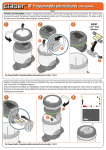
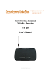
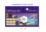
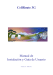
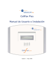
CELLROUTE-GSM
Fixed Wireless Terminal
www.discountcomms.co.uk
Installation & User Guide
Version .05 – Jan 2006
2
CELL Route-GSM
Document Control
Date
Apr 2003
June 2003
Dec 2003
Jan 2004
Jan 2006
Doc
Version
1
2
3
4
5
Change
Authority
1st release of document
Asset protection added
Adjustable gain settings & line reversal
Selectable confidence tone & Power fail Voltage
Notices & WEEE Directive symbol added
CH/TB
CH/TB
CH/TB
CH/TB
CH
Notices
Note: The cellRoute-GSM unit must be connected to the mains power and
allowed to charge for a minimum of 30 minutes before use.
Emergency Calls
This terminal operates using GSM signals, which cannot guarantee connection
in all conditions. Therefore, you should never rely solely
on the terminal equipment for essential communications such as medical or
emergency services.
If the mains plug is removed from the power socket the unit will switch to an
internal battery supply. As there will not be an Earth connection, the output
voltage to the telephone line will automatically be reduced. This is to comply
with the European Low Voltage Directive. This may result in miss-operation
when using in some types of telephone. This condition also applies for mains
failure.
No responsibility is assumed by TFM for the use or reliability of the CellRouteGSM when used in a situation or with other equipment not supplied or
specified by TFM.
TelecomFM shall accept no liability for any error or damages of any kind
resulting from the use of this document or the equipment it relates to.
The wording in this document may change from time to time. Please refer to
the TelecomFM web site WWW.telecomfm.co.uk for the latest release.
www.discountcomms.co.uk
3
CellRoute-GSM
Introduction
Thank you for the purchasing the Cell Route-GSM terminal.
The CellRoute-GSM incorporates:
• CellRoute-GSM terminal (1)
• Internal Antenna (2)
• RJ11 Telephone connector (3)
• RJ45 Data port (4)
• L.E.D Indicators (5)
• Power Connection (6)
• External Antenna Connection & Switch (7)
7
2
1
5
6
4
3
4
CELL ROUTE-GSM
Getting Started
Setting up the terminal
Remove the CELLROUTE-GSM from the packaging, and proceed as
follows:
Warning! To avoid damage do not connect power until you have
inserted the SIM card
• Install the SIM card. (Making sure the PIN lock is deactivated if applicable).
• Install the CELLRoute-GSM in preferred location following guidelines.
• Connect Power to the CELLRoute-GSM using Power Supply Provided.
• Connect a telephone to the CELLRoute-GSM.
• Check Signal Strength
• Make a test call
Note: The cellRoute-GSM unit must be connected to the mains power
and allowed to charge for a minimum of 30 minutes before use.
However for maximum battery standby performance the CellRouteGSM must be connected to the mains for a minimum of 4 hours.
Installing the SIM card
Slide open the SIM cover.
Slide back the SIM door and lift it up.
Slide the SIM into the SIM door making
sure that the clipped corner of the SIM card
lines up with the clipped corner of the SIM
Holder.
Close the SIM door.
Slide SIM door to lock the SIM in place.
Then replace SIM cover.
5
CELL ROUTE-GSM
Getting Started
Location Of Cell Route
For best reception locate your CellRoute-GSM close to a window or
on an external wall within a minimum of 330mm from any metallic
object. The unit must be a minimum of 1 meter from any other sensitive
electronic equipment.
DO NOT locate in direct sun light or near any direct heat source.
Mounting the CellRoute-GSM and Power Supply
Bracket
Using the template provided, mark
location and fix with screws supplied.
Mount the Power Supply bracket within 1
meter from the CellRoute-GSM.
Connecting a telephone or Computer
• Connect your telephone(s)
Into the RJ11 socket provided.
• Connect your Computer into the
RJ45 socket provided.
Connecting the power Supply
• Connect the Mains lead into the
power supply unit then into the AC outlet.
• Connect the power cord from the
power supply unit to the CellRoute-GSM.
Connecting external Antenna if required
To activate the external antenna,
move the antenna switch ( ) to the
up position and screw the external
antenna into the SMA connector provided.
External
Antenna
Internal
Antenna
SMA
Connector
SMA
Connector
6
CELL ROUTE-GSM
Getting Started
Powering Up CellRoute-GSM
Note: The cellRoute-GSM unit must be connected to the mains power
and allowed to charge for a minimum of 30 minutes before use.
On power up the RED and GREEN LEDs will flash 5 times.
The Green LED will come on and remains on. The RED LED will light up for
approximately 10 seconds and then go out for approximately 10 seconds. Once
the unit has logged onto the GSM Network the Red LED will come back on.
Making a test call
Make a test call with the phone connected to the CellRoute-GSM. On
completion of dialled digits you will hear a confidence tone indicating the call is
successful. (Pressing the # key after the dialled digits results in a faster dialup.)
The RED LED will start to flash when the handset is lifted on the telephoneindicating signal Strength. Once the call is connected the RED LED will flash for
45 seconds indicating signal strength then stop leaving both RED and Green
LED lit.
Number of flashes
0
1
2
3
Status
None/Poor
Average
Good
V- Good
Signal strength (in dB)
<-81dB
>-81dB & <-67dB
>-67dB & <-59dB
>-59dB
It is possible to Set Incoming & Outgoing volumes on CellRoute
Outgoing volume adjustment on microphone
To adjust the microphone level
• Lift the receiver
• Dial 0##6
• Dial 1 to 5 followed by # (1 sets lowest volume, 5 sets highest volume)
You will hear an acceptance tone once the digit has been dialled.
Incoming volume adjustment on speaker
To adjust the Speaker level
• Lift the receiver
• Dial 0##3
• Dial 1 to 5 followed by # (1 sets lowest volume, 5 sets highest volume)
You will hear an acceptance tone once the digit has been dialled.
7
CELL ROUTE-GSM
Getting Started
Answering Incoming calls
Lift handset and call is connected.
Missed Call
If both L.E.Ds are flashing simultaneously, this is identifying a missed call.
Switching Off the CellRoute
When switching off the CellRoute-GSM you must first unplug the power cord
from the CellRoute-GSM itself, otherwise this will activate Battery back-up.
Battery Backup
In the event of mains failure the CellRoute-GSM’s battery backup will
automatically activate, giving a standby time of approximately 12 hours and a
talk time of 2 hours (these figures are subject to humidity and temperature).
During a power failure when battery back-up is in use, you may experience a
delay of up to 4 seconds before dial tone is heard.
Network Lock
The CellRoute-GSM has a network lock feature. This is a network security
function. (For further details please contact your service provider)
SIM PIN Lock
The CellRoute-GSM has a SIM card PIN lock feature. This is a SIM card security
function. (For further details please contact your service provider)
Confidence Tone
It is possible to turn confidence Tone ON or OFF
Confidence Tone ON dial 0##561#
Confidence Tone OFF dial 0##560#
You will hear an acceptance tone once the digits have been dialled.
Ringing Cadence
It is possible to adjust the ringing cadence for incoming calls to cell route
To change dial 0##8 (1 – 4)
1=USA, 2=UK, 3=SPAIN, 4=ETR
You will hear an acceptance tone once the digits have been dialled.
• Data
Please refer to Data documentation.
• PC Fax
Please refer to Fax documentation.
8
CELL ROUTE-GSM
Troubleshooting
• First Things to Check If No Operation
1. Check that Power is connected.
2. Check that SIM card is installed correctly.
3. Check that the telephone is connected correctly.
• LED Status
1. If NO LED’s are lit.
• Check for mains power
2. If RED LED is flashing with high pitch Interrupted Tone when
handset lifted check the following:
• No SIM connected
• SIM has a PIN set and this is not recognised in Cellroute memory
• SIM has been swapped with a SIM that has a PIN set which is not
Recognised in Cellroute memory
• Network lock is set to on, with incorrect network SIM connected
3. If NO RED LED with low pitch Interrupted Tone when handset
lifted.
• Cannot detect a network signal. (See Reception is poor)
4. If RED LED flashing at 100ms on / off.
• CellRoute is networked locked and does not recognise the networked
SIM Installed (GPRS unit Only)
5. RED & GREEN LEDs flash 5 times.
• CellRoute is Initialising.
6. RED & GREEN LEDs flashing on / off at the same rate.
• Missed call Indicator.
7. RED & GREEN flashing alternately at the same rate.
• CellRoute in data mode operation.
• Dial Tone Is Not Heard
1. Check that Power is connected.
2. Are batteries charged (Min 30 minutes before use)
3. Check L.E.D status. (Both battery and signal strength LED should
be lit).
4. Check SIM lock is deactivated.
5. Check that the telephone connected is working correctly.
6. During a power failure when battery back-up is in use, you may
experience a delay of up to 4 seconds before dial tone is heard.
9
CELL ROUTE-GSM
Troubleshooting
• Noise Is Heard during a Call
This maybe due to poor signal strength or the unsuitable location of
the CellRoute-GSM. It is recommended that CellRoute-GSM is
positioned a minimum of 1 meter away from other telephones and
other electronic devices.
• Reception is Poor
The CellRoute-GSM comes with a built in antenna. However If you
are experiencing problems with poor reception, check that you are
getting adequate signal strength. This can be achieved by moving the
CellRoute-GSM to another location, for examples move closer to a
window or higher up in the building.
In some locations your Coverage area may require a higher gain
external antenna for optimal Call clarity and performance. An external
3Db antenna is supplied with the unit.(see Connecting external
Antenna)
Contact your service provider for advice on other types of external high
gain antenna that can be connected to CellRoute-GSM.
10
CELL ROUTE-GSM
Technical Specification
Telephony Interface
Call Control
Line Voltage
Loop Current
Line impedance
Ring Voltage
Ring Load
CLIP
DTMF
48v on hook
40mA off hook
600-ohm complex
70Vrms
REN 4
Bellcore FSK
Features Overview
High Ringer Equivalence POTS Interface
Supports up to 4 additional extensions
Highly compatible POTS user interface
Integral Battery Back-up
Caller Line ID Presentation (Bellcore)
GSM Interface
Bands
Transmit Power
Speech Codecs
E-GSM 900MHz
GSM 1800MHz
GSM Phase 2+
Class 4 (2W) for E-GSM 900 MHz Class 1 (1W)
for GSM 1800MHz
Half Rate (ETS 06.20)
Full Rate (ETS 06.10)
Enhanced Full Rate(ETS 06.50 /
06.60 / 06.80)
Additional GSM network features may be available
Subject to network availability and support
RS232 Data Port for emails/web and transmission /
reception of PC faxes (using WinFax Pro)
SIM lock for asset protection
(For details contact your service provider)
Network Lock for asset protection
(For details contact your service provider)
Remote Software Upgrades
Remote Antenna facility
Data Rate
2400,4800,9600,Baud
Off-hook Howler
SIM Card
3V
Gain adjustment on microphone 1>5
Antenna
Integral Omni directional Antenna
With MCX connector for external
Antenna option
Gain adjustment on speaker 1>5
Physical Interfaces
Power Supplies
Telephone
Analogue / RJ11
Primary
110-240Vac @ 47-63Hz
Data Port
RS232 / RJ45 with optional DB-9
Converter
Secondary
2xA size NiMH rechargeable batteries
with Auto switch over to mains failure
GSM Antenna
An SMA male connector
Performance
11 hours standby time (subject to
Humidity and temperature)
SIM Card
3V Small card retained under rear panel
Indication
2 x LED indication for battery / Transmission
Status
Up to 2 hours Talk time (subject to
Humidity and temperature)
Approvals
Physical Specifications
CE Certification to R & TTE directive 1999/S/SEC
Height
150mm
GSM Certifications:
Width
122mm
• ETS 300 607-1 Digital Cellular Telecommunications Systems
Depth
42mm
• EN 301 419-1 Global System for Mobile Communications
Weight
460gm
• ETS 300 342-1 Radio Equipment and Systems
Operational Temperature Range
0C to 45C