1
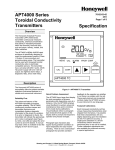
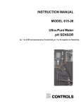
Moranlord Ltd
Unit 3H
Northland Business Park
Warnham
West Sussex
RH12 3SH
Tel: 01306-628480
Fax: 01306-628481
Email [email protected]
http://www.moranlord.co.uk
RM-33
Rinse Water Control System
User Guide
July 2012
Contents
1 Introduction
2 Principles of rinse water control using conductivity :- FAQs
3 Installing the RM-33
4 How the RM-33 operates
5 Setting the RM-33 to suit your process
6 Specifications
7 Options
8 Safety precautions
9 Block diagram
2
Section 1
Introduction
The RM-33 is a precision instrument that uses the latest contact-free electrodeless sensor
technology to control the use of rinse water.
The control of rinse water gives the following important advantages:Lower, more consistent water usage and cost.
More consistent chemical concentration in tank outflow resulting in simpler water treatment
process control.
Lower operator intervention needed to suit changing work patterns.
The RM-33 is a complete rinse water control system kit including everything required to
control the rinse water in a single swill tank. The kit comes pre-wired and installation time has
been reduced to a minimum.
A specially designed polypropylene encapsulated conductivity sensor is used to measure the
concentration of chemical contamination in the rinse tank, and a rugged solenoid valve is
used to regulate the flow of water.
The volume of rinse water flow is measured with an integrated digital flow meter.
The system uses low 24 volt power to operate the controller and solenoid valve, so that the
maximum safety benefits can be gained from use in the plating environment.
3
Section 2
Principles of rinse water control using conductivity FAQs
2.1 What is conductivity?
The conductivity of a liquid is a measure of its ability to conduct an electric current from one
point to another. In liquids this current flow is made possible by positively and negatively
charged ions, cations (+) and anions (-) respectively. When the liquid conducts a current the
ions move to the oppositely charged regions in the liquid, so the anions flow to the anode (+)
and the cations flow to the cathode (-). This is the basis of electrolytic conduction, the greater
the number of ions present, the greater the conductivity of the liquid.The two main techniques
for measuring conductivity are contacting sensors (electrode) and non-contacting sensors
sometimes known as electrodeless or toroidal.
2.2 How does an electrodeless sensor work?
Electrodeless, conductivity measurement does not require any electrode contact with the
liquid being measured. Instead, a pair of wire-wound toroidal cores encapsulated in a
protective body act as the sensor.
One toroid is driven with a constant voltage which generates a magnetic field in the liquid. In
turn the current induced by this magnetic field in the liquid magnetically couples with the
second toroid to produce a current. This current induced in the second toroid's windings is in
direct proportion to the amount of magnetic coupling, and so varies proportionally to the
conductivity of the solution. This current is amplified, and gives an output of conductivity in the
solution being measured.
2.3 Temperature Compensation
A characteristic of conductive liquids is that as their temperature increases so does their
conductivity. The conductivity measured at a certain temperature therefore has to be
compensated for so all readings for different liquids can be compared at a fixed temperature.
The RM-33 conductivity sensor actually contains signal processing electronics which carry out
temperature compensation, ensuring very accurate conductivity measurement with variations
in water temperature.
2.4 What are the units of conductivity?
Conductivity of water is expressed in the inverse of resistance, and the units are Siemens.
One Siemen represents a very conductive solution and is not usually experienced in most
situations, so a smaller unit is used, the micro-Siemen.
There are 1000,000 uS to 1 Siemen.
2.5 How conductive is water?
Distilled water and de-ionised water have low conductivity. The conductivity of water purified
in this way is about 2-5uS.
2.6 What is the conductivity of my water supply?
The baseline conductivity of the water supply varies from area to area, and there is also a
small variation over time dependent on the amount of dissolved solids in the water supply.
This conductivity is usually in the region of 100 to 700 uS.
2.7 How can I measure the baseline conductivity of my water supply?
Baseline conductivity of the water supply can be measured with our new compact
electrodeless conductivity meter – the Stick Meter 5JI. It is ideally suited for this purpose and
is specifically designed for on-site dipping into water supply and rinse tanks giving precise
conductivity measurements.
The meter used to measure baseline conductivity must be recently calibrated as otherwise it
may give false reading which will cause problems.
4
Fig 2.7 – Stick Meter 5JI.
Another way of measuring the baseline conductivity is to fill the rinse tank with clean water
and take a reading from the RM-33 in the
mode.
When measuring the baseline conductivity, it is essential to ensure that the tank is fairly clean
of deposits and chemicals, as this value will be needed for the correct setting of the control
set-point.
2.8 How does this apply to the regulation of rinse water in my rinse tank?
When work parts enter a rinse tank, they carry in chemicals from a previous process, and this
carry in of chemicals causes the conductivity of the water to rise in proportion to the strength
of the ionic solution formed.
The RM-33 monitors the conductivity of the rinse water, and opens the water control
valve into the rinse tank when a preset level of conductivity is reached.
The set-point will be determined by the type of process and the level of rinse water purity that
is required. Factors to consider are staining, discoloration, rusting, or contamination of
following processes.
2.9 What should I use as an initial setting for the RM-33?
Section 5 gives details of how to set up the RM-33.
5
Section 3
Installing the RM-33
3.1) Fitting Conductivity Sensor in rinse tank:
Step 1) Positioning Sensor & rinse tank considerations:
The correct positioning of the sensor is critical to ensure the optimal performance from your
system. In a counter-flow system the sensor goes in the clean final swill. The sensor should
be positioned by the tank outflow or, in the case of a counter-flow system, by the weir into the
dirty swill.
Depending on your tank design, this is usually in the corner diagonally opposite the water
feed, as shown in the diagram below. A sensor position on the same side of the tank as the
outflow, and the opposite side to the water entry is acceptable.
Fig 3.1a – Typical tank layout.
It is important that the sensor is not next to the water supply to the tank as this will dilute the
reading, and cause the water control valve to cycle needlessly.
The tank sensor comes with 5m of cable to connect to the control unit. Extension cables in
5m and 10m lengths are available if necessary, depending on where the control unit is to be
mounted.
6
Water supply pipe
It is good practice to direct the water supply pipe back towards the edge of the tank so that
water is forced to mix as much as possible before exiting the tank. This can be achieved by
fitting an elbow on the end of the inlet pipe. A baffle can be used to achieve the same result.
Fig 3.1b – directing water feed pipe.
Step 2) Mounting the conductivity sensor to the tank
The sensor clamps to the side of the tank – tighten the screw so that the sensor is held firmly
in place.
Fig 3.1c – tank conductivity sensor clamp.
It is possible to add a rubber gasket that goes between the clamp plate and the tank side for
increased grip.
7
Adjusting sensor submersion depth
The sensor head up to the welding joint must be completely submerged in water as shown in
picture below. The position of sensor mounting clamp can be adjusted by moving the clamp
up and down the sensor tube until desired level of submersion is achieved.
Lowest limit
of water level
Fig 3.1d – lowest possible sensor submersion depth in rinse water.
8
3.2) Installing Water Control Valve & Flow Meter Module.
Note Flow Direction
Fig 3.2a – water control valve & flow meter module.
The RM-33 has a pre-assembled water control valve and integrated flow meter module.
Connecting to pipe work:
The module is terminated at either end with plain 25mm PVC socket unions for insertion into
the water feed pipe work.
IMPORTANT: Ensure that you fit the solenoid and flow meter in the correct water flow
direction (marked by arrow on valve – see fig 3.b above). The preferable orientation of the
valve is with the operating coil uppermost. Take care the excessive strain is not placed on the
flow meter wire and that there is some slack in the wiring when in its final position.
Prepare the sockets first with an abrasive paper and ensure they are clean using a suitable
solvent.
Apply a thin, even layer of glue to both the pipe and the solenoid adaptor and push both firmly
together. It is important to ensure that solvent is not allowed to enter the valve body/flow
meter assembly itself, otherwise damage may occur to the valve seating and sealing as well
as to the flow meter bearings.
The module comes pre-wired to 5m of cable for connection to the control unit cabinet.
Extension cables in 5m and 10m lengths are available if necessary depending on the
mounting position of the control unit.
IMPORTANT:
Remember to wait until the solvent adhesive is thoroughly hardened before
pressurising the system.
The flow meter and valve assembly contain very small orifices which can be blocked
by debris in the water system.
Ensure that the pipe system is flushed through before fitting the assembly.
9
3.3) Installing the Control Unit
With the sensor fitted to the tank and the water control valve and flow meter module fitted in
the water feed the next step is to install the control unit.
Fig3.3a – the control unit.
10
Mounting the control unit.
Mount the control unit at a convenient wall position where it will not be subjected to direct
spills of water or chemicals. The control unit has 3 mounting points, 2 at the lower corners
and one on the upper rear of the case.
Drilling measurements are moulded on the rear of the case.
The cabinet should be positioned within reach of the water control valve module, the tank
conductivity sensor and a mains supply. However if the cabinet has to be mounted further
away than the 5m reach of the cables, 5m and 10m extension cables are available for both
the water control valve/flow meter module and the tank sensor.
Connections:
Valve /
Flow Meter
Power
24V DC
Sensor
Fig 3.3b – connections to the control unit.
The water control valve/flow meter module plugs into the 6-pin socket, and the conductivity
sensor plugs into the 4-pin socket as shown in picture above.
When plugging in the connectors line up the polarising keyways on the plug and socket, push
gently in and then turn the locking ring gently clockwise to hold in place.
Power Supply Connection
RM-33 system comes with universal switching power supply which is able to operate on both
110 volts and 240 volts mains voltages. The power supply is mounted in separate waterproof
box and supplies 24 volts DC. The power cable has 3-pin female socket on one end and 3-pin
male connector on another end. The female socket plugs into the controller while the male
connector plugs into the power supply. The mains cable comes with 3-amp fused English
mains plug by default, although other plugs may be fitted upon customer’s request.
11
Fig3.3c – control unit’s power supply with power cable
12
Section 4
How the RM-33 operates
4.1 The control panel:
Adjust up/down
Flow meter
Tank conductivity
Mode select
Conductivity set-point
Valve open
Fig 4.1a – RM-33 control panel.
In order to switch between display modes press the Mode select button – the selected mode
will be indicated by a red LED. All values are displayed on the LCD display.
The display modes are as follows:
– flow meter display mode. The RM-33 has an integrated digital flow meter.
In this mode the amount of water used is displayed in cubic metres and litres.
– tank conductivity display mode. In this mode the conductivity of the rinse tank
is displayed in S.
– set-point adjust mode. In this mode the set-point conductivity value at which
the water control valve starts dosing the rinse tank is determined.
13
– solenoid open. A blue led comes on whenever the conductivity is above the
set-point to indicate that the water control valve is set to open. If the water valve
has been shut for less than 10 seconds however, the LED will light, and the
valve will open after a delay to prevent the valve from excessive wear.
4.2 Viewing rinse tank conductivity:
To view the conductivity of the rinse water in the tank;
-
Repeatedly press the Mode select button until the
-
The LCD display indicates the level of conductivity in the tank in S.
LED lights up.
4.3 Adjusting rinse water conductivity set-point:
To adjust the rinse water conductivity set-point at which the water control valve opens
to control the tank carry-in level;
-
Repeatedly press the Mode button until the
-
Hold the Mode button down for 10 seconds and the
LED lights up.
LED will start
to flash.
-
Now use the Up/Down adjust buttons to change the Set-point indicated
on the LCD display to the desired value.
-
Once the desired set-point is reached, press the Mode button - this value
will be stored as the new set-point and the water control valve will now be
opened whenever this value is reached.
14
4.4 Water flow meter:
How to show the amount of rinse water used;
-
Repeatedly press the Mode select button until the
-
The display first shows the cubic metres of water used (1000’s of litres).
-
By pressing the mode button again (
LED is illuminated.
LED still illuminated) the
remaining litres (indicated by an L on the display) are displayed.
-
Once the counter reaches 9, 999, 999 litres it will roll over to zero. If you
wish to manually reset the counter to zero litres at any time press the
up/down buttons simultaneously.
15
Section 5
Setting the RM-33 to suit your process
5.1 Establish the baseline water supply conductivity
Section 2.7 details how this can be done using the RM-33 or the Stick Meter 5JI.
5.2 Adjusting the set-point level to suit your process
If the set-point level is adjusted to be the same conductivity as the incoming water supply,
then the solenoid will open continuously, and no water saving will be made. Setting the setpoint to a higher value will cause the water control valve to close until such time as the rinse
water contamination reaches the conductivity level that is set. The higher the value above the
incoming water conductivity, the more contamination will be permitted, and the more water
will be saved. The exact level to be set is very much a matter of judgment where the quality
and sensitivity of the processes to rinse water contamination will be the deciding factor.
The table below is a good starting guide for setting the system initially. Generally speaking,
processes that require conductivity levels of less than 500uS will require demin water in order
to meet the uS levels that are shown below, unless local water purity is unusually high in that
area.
One way of empirically determining the set-point is to set it to a very high value which will
effectively shut off the water supply to the tank, at a time when it contains clean water, and
take note of the conductivity reading during rinse tank use.
Take note of the reading in uS, when the contamination has reached a level which is
estimated to be acceptable. This can be used as the control set-point, and then further refined
if more savings are required.
Guideline Rinse water Contaminant Limits
Alkaline cleaner
1,700 S
Hydrochloric acid
5,000 S
Sulfuric acid
4,000 S
Tin acid
500 S
Tin alkaline
70-340 S
Gold cyanide
260-1,300 S
Nickel acid
640 S
Zinc acid
630 S
Zinc cyanide
280-1,390 S
Chromic acid
450-2,250 S
16
Section 6
RM-33 Specifications
RM-33 Kit comprises:
Control unit (wall-mounted)
Enclosure dimensions : 180 x 240 x 120 mm (HxWxD)
Power Supply:
220V to 250V AC supply
Display:
0 – 9999 S temperature compensated conductivity, resolution 1 S
LCD display.
Valve opening set-point: 0 - 9999 S in 1 S increments.
Set-point Hysteresis:
none, solenoid off-time is restricted to 10secs min
Enclosure IP:
to IP65
External Connections: IP68 connectors
Mains plug:
3amp fused
Conductivity sensor
Electrodeless technology (no cleaning required).
High temperature all-polypropylene construction.
Cable length:
5m
Water control valve & flow meter module
24VDC Burkert Fluid Control Systems type 6213 13mm dia seat direct acting.
Integrated digital flow-meter.
Other valves to suit, eg larger seat sizes for low pressure operation.
Cable length
5m
RM-33-DI Kit comprises:
Control unit (wall-mounted)
Enclosure dimensions : 180 x 240 x 120 mm (HxWxD)
Power Supply:
220V to 250V AC supply
Display:
0 – 999.9 S temperature compensated conductivity, resolution
0.1 S LCD display.
Valve opening set-point: 0 – 999.9 S in 0.1 S increments.
Set-point Hysteresis:
none, solenoid off-time is restricted to 10secs min
Enclosure IP:
to IP65
External Connections: IP68 connectors
Mains plug:
3amp fused
Conductivity sensor
Stainless Steel contacts.
High temperature all-polypropylene construction.
Cable length:
5m
Water control valve & flow meter module
24VDC Burkert Fluid Control Systems type 6213 13mm dia seat direct acting Stainless Steel
Integrated digital flow-meter.
Cable length
5m
17
Section 7
Options:
Audible Alarm Option: RM-33-A
An option allows the factory addition of an audible alarm which is actuated if the feed water
flow drops below 4 litres/min as would occur in the case of a failure in the water supply, or a
tap being closed inadvertently.
This can offer an important safety feature which can prevent lost work when used with robotic
lines.
The alarm can be cleared by pressing the up or down keys but will sound again after 1 minute
if the flow is still below 4 litres/min.
Tank Sensor Extension Cable: RM-33-S5, RM-33-S10
Extension cable available in 5 and 10 metre lengths.
Water control valve/Flow meter Extension Cable: RM-33-V5, RM-33-V10
Extension cable available in 5 and 10 metre lengths.
Compact electrodeless conductivity meter Stick Meter 5JI
Small and easy to use conductivity meter designed for on-site dipping into rinse tanks and
water supply. It uses the same electrodeless technology as the RM-33 sensor. The meter is
autoranging and measures conductivity from 1µS to 500mS, and temperature as well.
18
Section 8
Safety precautions
The RM-33 can be used in environments where toxic and corrosive chemicals are present.
The user of this system must be aware of dangers of these hazardous substances and take
all necessary precautions in this respect when installing and using the RM-33.
The RM-33 control unit must be powered by suitable 24 volts DC power supply. Ensure that
proper cables with the right connectors are used, and never try to cut or shorten the mains
lead.
CAUTION!
To avoid electric shock never place the power supply in places where water could get
inside, and never open the box of power supply as it contains live mains voltage!
Never attempt to connect the control unit directly to the mains, and never short circuit
the output of power supply as it will result permanent damage to the control unit or
power supply!
If conductivity sensor needs to be replaced use protective clothing to protect your skin from
hazardous chemicals, and make sure that sensor surface is rinsed after pulling the sensor out
of the tank. Care should also be taken to avoid electrical shock when it is used in an
electroplating environment, since although the body of conductivity sensor is made of
insulator, circumstances can occur when current may track across the wetted surface of the
sensor.
19
Section 9
Block Diagram
Conductivity
Sensor
Mains
input
Solenoid
valve
RM-33
Control board
Flow
meter
Optional
RM-33-A
Alarm
RM-33
control unit
20
110-240V to 24V
power supply