1
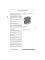
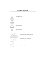
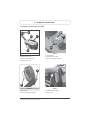
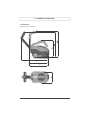
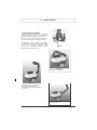
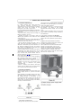
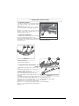
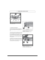
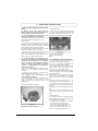
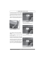
User Guide
VCSD-01 Mains Powered
Scrubber drier
VCSD-02 Battery Powered
Scrubber drier
0121 347 6047
[email protected]
vaxcommercial.co.uk
2
1 - CONTENTS
1 - CONTENTS
2.3
2.4
2.5
7.13.1
7.13.2
2 - GENERAL INFORMATION
2.1
MANUAL PURPOSE
2.2
T E R M I N O L O GY
AND SYMBOL LEGEND
PRODUCT IDENTIFICATION
SPECIFIC USE
ECHNICAL MODIFICATIONS
7.13.3
7.13.4
7.13.5
7.14
3 - SAFETY INFORMATION
3.1
BASIC RECOMMENDATIONS
3.2
SCRAPPING OF THE MACHINE
3.3
NOISE AND VIBRATIONS
8 - MAINTENANCE
8.1
TANKS
8.2
SOLUTION FILTER CLEANING
8.3
SUCTION HOSE
8.4
SQUEEGEE
8.5
ACCESSORIES
8.6
MACHINE BODY
8.7
BATTERY*
8.8
THERMAL BREAKERS
8.9
PERIODIC MAINTENANCE
8.9.1
DAILY OPERATIONS
8.9.2
WEEKLY OPERATIONS
8.9.3
OPERATIONS AT EXTENDED
INTERVALS
8.10
RECOMMENDED SPARE PARTS
4 - HANDLING INSTRUCTIONS
4.1
PACKING LIFTING AND TRANSPORT
4.2
CHECKS UPON DELIVERY
4.3
UNPACKING
4.4
DIMENSIONS AND WEIGHT OF THE
PACKAGING
5 - TECHNICAL INFORMATION
5.1
SYMBOLS USED ON THE MACHINE
5.2
MACHINE STRUCTURE AND
FUNCTIONS
5.3
DIMENSIONS
6 - INSTALLATION
6.1
HANDLEBAR POSITIONING
6.2
BATTERY INSTALLATION*
6.2.1
BATTERY CONNECTION*
6.3
BATTERY CHARGER CONFIGURATION*
9 - TROUBLESHOOTING
9.1
THE MACHINE DOESN’T WORK
9.2
THE BRUSH DOESN’T ROTATE
9.3
NOT ENOUGH OR NO CLEANING
SOLUTION
9.4
NO SUCTION
9.5
INSUFFICIENT SUCTION
9.6
THE BRUSH MOTOR OR THE
SUCTION MOTOR DOESN’T STOP
9.7
THE SQUEEGEE DOESN’T CLEAN OR
DRY EFFICIENTLY
9.8
THE BATTERIES DO NOT WORK*
9.9
THE BATTERIES DO NOT CHARGE OR
DO NOT HOLD A CHARGE*
7 - OPERATING INSTRUCTIONS
7.1
MACHINE PREPARATION
7.2
BATTERY CHARGING*
7.3
BRUSH ASSEMBLY / DISASSEMBLY
7.4
MACHINE TRANSPORT
7.5
SQUEEGEE ASSEMBLY
7.6
SQUEEGEE DISASSEMBLY
7.7
SQUEEGEE BLADES DISASSEMBLY/
ASSEMBLY
7.8
SQUEEGEE ADJUSTMENT
7.9
FILLING AND DRAINING THE
SOLUTION TANK
7.10
DRAINING THE RECOVERY TANK
7.11
ADJUSTING THE SOLUTION WATER
FLOW
7.12
DRIVING THE MACHINE
7.13
WORK METHOD
* Only applies to VCSD-02 model
PREPARATION AND WARNINGS
BATTERY CHARGE LEVEL
CONTROLS*
DIRECT SCRUBBING OR FOR
SLIGHTLY DIRTY SURFACES
INDIRECT SCRUBBING OR FOR
VERY DIRTY SURFACES
POST-SCRUBBING OPERATIONS
SPECIFIC INSTRUCTIONS FOR THE USE
OF VCSD-02
2
2 - GENERAL INFORMATION
2.1 MANUAL PURPOSE
To make it easier to read about and look up various
subjects, refer to the table of contents at the
beginning of this manual.
This manual has been prepared by the
manufacturer and is an integral part of the product.
As such, it must be kept in a safe place for the
machine’s en- tire service life until demolition.
The customer must ensure that machine operators
have read or are familiar with the contents of this
manual so that they strictly follow the instructions
described herein.
Constant compliance with the instructions provided
in this manual is the only way to guarantee the best
results in terms of safety, performance, efficiency
and service life of the product you now own. Noncompliance with these rules may cause injuries to
people and damage to the machine, the scrubbed
surface and the environment: in no case can such
injuries or damage be attributed to the
manufacturer.
This manual refers in detail to the machine and provides instructions and descriptions only about the
battery and the battery charger provided.*
2.2 TERMINOLOGY AND SYMBOL LEGEND
For the sake of clarity and to efficiently highlight
the various aspects of the instructions provided,
terms and symbols were used that are defined and
illustrated here below:
- Machine.
This
definition
replaces
the
commercial name to which this manual refers.
- Operator. An operator is considered the person
who normally uses the machine and is familiar with
its operating features but does not have the
specific technical skills to work on that machine.
- Technician. A technician is considered a person
who has the experience, technical education,
legislative and regulatory knowledge that allows
him to carry out any type of required work, and the
ability to recognize and to avoid possible risks
during machine installation, operation, handling
and maintenance.
- INDICATION SYMBOL (☞). Particularly
important information to avoid machine
malfunctions.
- ATTENTION SYMBOL (!). Very important
information to avoid serious damage to the machine
and to the environment in which it operates.
- DANGER SYMBOL ( ◊). Vital information
provided to avoid serious (or extreme)
consequences affecting the health of persons
and causing damage to the product and the
environment in which it operates.
* Only applies to VCSD-02 model
4
2.3 PRODUCT IDENTIFICATION
The nameplate located in the backside of the
machine contains the following information:
• Manufacturer ID
• CE mark
• Model code
• Model
• Overall power rating
• Serial number
• Year built
2.4 SPECIFIC USE
This machine is a floor scrubber-drier: it must be
used to scrub and to vacuum liquids of flat, rigid,
horizontal, smooth or moderately rough and
uniform floors that are free from obstacles in both
civic and industrial environments. Any other use is
prohibited.
Please refer very carefully to the safety information
reported in this manual.
The scrubber-drier distributes a quantity of a water
and detergent solution (adjustable) on the surface
to be cleaned, while the brushes remove any dirt on
the ground. The machine’s suction system, using a
ground squeegee, perfectly dries the liquids and
the dirt just removed from the front brushes in a
single pass.
By efficiently combining a cleaning detergent with
various types of brushes (or abrasive disks), the
machine can adapt to all the various combinations
of floors and dirt.
2.5 TECHNICAL MODIFICATIONS
This machine was designed and built in accordance
with the fundamental requirements for user safety
and health as set forth in European directives. For
this reason the CE mark was placed on the ID label.
The European directives to which the equipment
conforms are referenced are available upon request.
This certificate will become invalid if the equipment
is modified in any way without the manufacturer’s
prior authorization.
The manufacturer reserves the right to make
technical modifications to the product, without prior
notice, in order to make the necessary technical
upgrades or improvements. For this reason, some
details of your machine may be different from the
information in the sales catalogues or from the
illustrations presented in this booklet. However, this
will not reduce safety or invalidate the information
supplied to this regard.
3 - SAFETY INFORMATION
3.1 BASIC RECOMMENDATIONS
(☞) Carefully read the “instruction manual”
before
starting,
using,
performing
unscheduled or routine maintenance or
any other work on the machine.
(! ) Rigorously comply with all the
instructions provided in this manual and in
those for the batteries and battery chargers
(with particular attention to warnings and
danger notices).*
The manufacturer will not be held
responsible for injuries to persons or damage
to property due to non-compliance with
the aforementioned instructions.
(☞) Before using the machine, make sure that
each part is in the correct position.
(! ) The machine should only be used by
personnel who have received appropriate training.
To avoid unauthorized use, keep the machine in a
place that denies access to unauthorized
personnel when not being used and remove the
key from the control panel.
(! ) This commercial appliance can be used by
those under 16 (but not below 8) years and
persons with reduced physical, sensory or mental
capabilities or lack of experience and knowledge if
they have been given instruction concerning use of
the appliance in a safe way and understand the
hazards involved. Cleaning and user maintenance
shall not be performed without supervision.
(! ) Do not operate this machine for any other
purpose except for the use for which it was
specifically designed. Evaluate the type of building
where it will be utilized and rigorously comply
with the current safety regulations and conditions.
(◊) Do not use the machine in places without
adequate lighting, in explosive environments,
when harmful dirt is present (dust, gas, etc.), on
roads or public passageways and in outdoor
environments in general.
( ! ) The machine operating temperature range is
+4°C to +35°C; when not being used, store the
machine in a dry and non-corrosive environment
within a temperature range of between + 10°C and
+50°C. When using the machine under any
condition the humidity must range between 30%
and 95%.
(◊) Never use or vacuum liquids, gases, dry
dust, acids and solvents (e.g. paint thinners,
acetone, etc.), even if diluted, inflammables
or explosives (e.g. petrol, fuel oil, etc.); never
vacuum flaming or incandescent objects.
( ! ) Do not use the machine on slopes or
ramps steeper than 2%.
For small slopes, do not use the machine sideways,
always handle it with caution and never move backwards. When transporting the machine on steeper
ramps or slopes, be very careful to avoid tipping
and/or uncontrolled accelerations.
* Only applies to VCSD-02 model
5
The machine can be handled on ramps and/or
steps only with the brush head and squeegee lifted
off the ground.
(!) Never park the machine on a slope.
(☞) Never leave the machine unattended with the
key in and connected; it may be left only after
having disconnected it and taken the key out and
guaranteeing against accidental movements
and, if necessary, disconnecting it from the
electrical power supply.
(◊) Make sure there are no other persons, and
children in particular, in the area where the machine
is being used.
(!) Do not use the machine to transport
persons/things or to tow objects. Do not tow the
machine.
(☞) Do not use the machine as a support surface
for any weight for any reason.
(☞) Do not block or cover any openings
(!) Do not remove, modify or by-pass the safety
devices.
(!) The appropriate Personal Protective
Equipment should be worn to operate the
machinery and protect the user. This should be
in accordance with an appropriate risk
assessment prior to its first use. Before starting
to work, remove necklaces, watches, ties and
other objects that may cause serious injuries.
(!) Do not insert hands between moving parts.
(☞) Do not use detergents that differ from those
recommended and follow the instructions
indicated on the chemical’s relevant safety d at a
sheets. Follow all storage, disposal and safety
instructions of each individual or group of
detergents as listed on the product.
(!) Make sure that the battery charger power
sockets are connected to an efficient earthing
system and that they are protected by magneto
thermal and differential circuit breakers.*
(!) Follow the battery manufacturer’s instructions
and comply with safety instructions and legal
provisions. The batteries should always be clean
and dry to avoid surface leakage currents.
Protect the batteries against impurities, such as
metallic dust.*
(◊) Do not place tools on top of the batteries: they
may cause a short-circuit or an explosion.
(◊)Never spray water on the machine to clean it.
(☞) Recovered fluids contain detergents,
disinfectants, water, as well as organic and
inorganic material
collected during
work
operations: dispose of them in accordance with
current legal provisions.
3 - SAFETY INFORMATIONS
Each homogeneous group must be
accordance with recycling laws. In
recommended to eliminate those
machine that may be dangerous,
children.
(! ) If the machine malfunctions and/or operates
inefficiently, turn it off immediately (disconnecting
from the electric power supply or from the
batteries) and do not tamper with it. Contact the
Vax contact centre.
(◊) All maintenance or accessory replacement
operations must be carried out in environments
with adequate lighting and only after having
disconnected the machine from the electric power
supply or by detaching the battery connector.
(☞) All work on the electrical system and all
maintenance and repair operations (especially
those not explicitly described in this manual)
should be carried out only by authorized service
centers or by specialized technical personnel who
are experts in the sector and in the pertinent
safety regulations.
(☞) The machine owner can only use
original accessories and spare parts
supplied exclusively by the manufacturer
since such parts are the only ones that
guarantee that the equipment will operate
safely without any problems. Do not use
parts disassembled from other machines or
other kits as spare parts.
disposed of in
addition, it is
parts of the
especially for
As owner of an electrical or electronic
product, you are not allowed by law
(according
to
EU-Directive
2002/96/EC of 27 January 2003 on
waste electrical and electronic
equipment and the particular national
laws of the EU-Member States transforming this
Directive) to dispose of this product or its
electrical/electronic accessories as unsorted
domestic waste. You shall use the designated
gratis possibilities for re- turn instead.
3.3 NOISE AND VIBRATIONS
- Acoustic pressure: LpL = 73 dB
- Acoustic power measured: LwA = 82 dBA
- Acoustic power granted: LwA = 83 dBA
- Vibrations: 0,29 m/s² (Uncertainty ±15%)
(☞) Before each use, check the machine and, in
particular, check that the battery charging cable and
the connector are in perfect condition and safe
for use. If they are not in perfect condition, do not
use the machine for any reason until an authorized
specialist repairs the defective parts.
(☞) Do not use the machine on textile flooring,
such as rugs, carpeting, etc.
(☞) If foaming or leakages occur, immediately turn
off the suction motor. Wax, foaming detergents or
dispersions along the hoses may cause serious
problems for the machine or clog the hoses.
3.2 SCRAPPING OF THE MACHINE
If the machine will no longer be used, remove the
batteries and dispose of them in accordance with
the eco-compatibility regulations as set forth in
European standard 91/157/EEC or deposit them in
an authorized collection centre.
To dispose of the machine, comply with the current
laws where it is used:
- disconnect the machine from the mains and clean
it after emptying any liquids;
- separate the machine into groups of
homogeneous materials (plastics in accordance
with the recycling symbol, metals, rubber,
packing). For parts containing different materials,
contact the competent authorities;
6
4 – HANDLING INSTRUCTIONS
4.1 PACKING LIFTING AND TRANSPORT
During all lifting or transportation make sure that
the packed machine is securely anchored to
prevent it from tipping over or falling accidentally.
Transport vehicle loading and unloading operations
must be carried out with adequate lighting and by
trained professionals only.
The packed machine must be handled using
adequate devices, making sure not to
damage/strike any part of the packing, not to tip it
over and to be very careful when placing it on the
ground.
(☞) All these instructions also apply to the batteries and the battery charger. *
4.4 DIMENTIONS AND WEIGHT OF THE
PACKING
4.2 CHECKS UPON DELIVERY
(☞) When the goods are delivered (machine,
battery or battery charger) by the transporter,
carefully check the condition of the packing and its
contents. If the contents have been damaged,
notify the transporter and reserve the right, in
writing (select the word “reserve” on the
document), to submit a claim for compensation
before accepting the goods.
4.3 UNPACKING
(! ) Wear safety clothing appropriate to those
identified by a qualified risk assessment.
The machine is packed with in a cardboard housing
placed on a wooden crate; to unpack the machine
carry out the following steps:
- Use scissors or clippers to cut and eliminate the
plastic straps.
- Slip off the cardboard housing from the top of the
packed machine.
- Remove the envelops inside and check their contents (use and maintenance manual, battery
charger connector*, power cable**)
- Remove the metallic brackets or plastic straps that
secure the machine to the pallet. You will require
an adjustable spanner or socket set to do this.
- Take out the scrubber pad from the packaging
(the squeegee is already attached to the unit)
- Take the machine off the pallet (pushing it backward) by using an inclined surface that is solidly
attached to the floor and to the pallet.
It is recommended to keep all the pieces of the
packing since they might be useful in the future to
protect the machine and the accessories during
transport to another location or sent for
evaluation/repair. If not, the packing can be
disposed in accordance with current disposal laws.
* Only applies to VCSD-02 model
** Only applies to VCSD-01 model
7
Volume: Weight:
0,38 m³
Model VCSD -01
53 kg
Model VCSD -02 (with battery)
61kg
Model VCSD -02 (without battery)
41.5 kg
5 – TECHNICAL INFOMATION
5.1 SYMBOLS USED ON THE MACHINE
General ON/OFF switch
Brush motor switch
Suction motor switch
Solenoid valve switch
Symbol of the solution water flow adjustment
Symbol of the recovery tank drain hole
Symbol of the squeegee lifting/lowering
8
5 – TECHNICAL INFOMATION
5.2 MACHINE STRUCTURE AND FUNCTIONS#
A
B
C
C
A
D
Photo 3
Photo 1
A) Handlebar
A) Suction filter
B) Recovery water tank
B) Automatic shut-off float
C) Suction compartment cover
C) Recovery tank inspection plug
D) Solution water tank
B
B
A
A
Photo 4
Photo 2
A) Control lever
A) Handlebar release pedal
B) Suction hose
B) Squeegee lifting/lowering lever
#
Images shown may vary from the final product
9
5 – TECHNICAL INFOMATION
Model VCSD-01
A) General ON/OFF switch
B) Suction motor switch
C) Solenoid valve switch for solution
water outlet
D) Brush motor switch
Model VCSD-02
A) Suction motor switch
B) Solenoid valve switch for solution
water outlet
C) Brush motor switch
C
Model VCSD-02
Model VCSD-01
A) Power supply cable
A) General ON/OFF key / battery
cut-out switch
B) Protecting cap
C) Battery charger
10
#
Images shown may vary from the final product
5 – TECHNICAL INFOMATION
5.3 DIMENSIONS
All dimensions are in centimetres.
114
81
79
11
6 - INSTALLATION
6.1 HANDLEBAR POSITIONING
To place the machine handlebar in the working
position (handlebar opened) it is necessary to
operate the handlebar release pedal (Photo 9 - A);
press the pedal, pull the handlebar towards you
and place it in the appropriate working position.
The handlebar can be set in three fixed positions:
one “handlebar closed” position for the machine
storage or the machine transportation (Photo
10) and two “handlebar opened” working
positions (Photo 11 and Photo 12).
A
Photo 9
Photo 10
Handlebar closed position
Photo 11
Handlebar opened - middle position.
To operate in small spaces it is
recommended to set the handlebar in
this position.
Photo 12
Handlebar opened
12
6 - INSTALLATION
6.2 BATTERY INSTALLATION*
The battery compartment is placed underneath
the recovery tank (Photo 14) and to access it, it is
necessary to remove the recovery tank. To
remove the recovery tank, detach the suction
hose from its housing (Photo 4 - B) and lift the
tank by pulling it up as shown in Photo 13.
Place the battery in the battery compartment
(Photo 14) checking that it is in perfect condition.
6.2.1 BATTERY CONNECTION*
(◊) Attach the battery wiring to the battery,
connecting the terminals only on the poles
marked with the same symbol (red wiring
“+”, black wiring “-“) as shown in the
connection diagram in Photo 15.
Photo 13
(◊)Take care to avoid short circuits over the
battery terminals
After checking that all the controls on the panel are
in position “0” or at rest, connect the battery
connector to the machine connector (Photo 16 B). Photo 16 shows the correct battery
connection.
( ! ) Close the battery compartment, replacing
the recovery tank, making sure not to crush any
wire.
6.3 BATTERY CHARGER CONFIGURATION*
( ! ) The machine is equipped with a battery
charger
configured
for
ENERSYS
maintenance free battery.
We recommend that you use an ENERSYS battery
as replacement. Use of any other battery may
affect the warranty of the product.
Photo 14
A
Photo 15
D
A) 12V Battery with cabling
B) Battery connector
C) Suction motor thermal breaker
B
C
D) Traction motor thermal breaker
Photo 16
* Only applies to VCSD-02 model
13
7 – OPERATING INSTRUCTIONS
7.1 MACHINE PREPARATION
( ! ) Before starting work, select and apply
any
personal protective
equipment
as
appropriate to any risk assessed by a qualified
person when using the machine or any
detergents to be used in conjunction.
(☞) Do the following before starting to work. Refer
to the relative sections for a detailed description of
these steps:
- Check the battery charge level and charge the
battery if necessary (see 7.2).*
- Assemble the brush or pad driver (with the
abrasive pad) suitable for the surface and work
involved (see 7.3).
- Check that the squeegee is solidly attached and
connected to the suction hose and that the drying
blades are not too worn (see 7.5).
- Fill the detergent solution tank with a mix of
clean water and non-foaming detergent in an
adequate concentration (as per the directions on
the detergent packaging) through the anterior
hole. Leave 2 cm between the mouth of the plug
and the level of the liquid (see 7.9).
(!) Ensure that the arrow on the lid of the Suction
compartment cover align with the arrow on the
Solution Water Tank to avoid reduction in suction.
(☞) To avoid risks, become familiar with the
machine movements by carrying out test runs on a
large surface without obstacles.
(!) To obtain the best results in terms of cleaning
and equipment service life, you should do the
following simple but important operations:
- Identify the work area, moving all possible
obstacles out of the way; if the surface is very
extensive, work in continuous and parallel
rectangular areas.
- Choose a straight work trajectory and begin
working from the farthest area to avoid passing
over areas that have already been cleaned.
The progress of the charging process is shown by
three LED’s: red, yellow and green, as in the whole
range of the battery chargers.
The green LED (Photo 18 - C) shows the end of
the charging – the battery is fully charged.
Disconnect the battery charger from the mains
power.
( ! ) For further information refer to the use and
safety manual of the battery charger provided by
the manufacturer.
If the machine is equipped with Pb-Acid
batteries, charge only in a well-ventilated area,
remove the recovery tank and open the battery
plugs.
(�) Follow the steps indicated in the battery
manufacturer’s operating and safety manual (see
the battery maintenance section).
Use an hydrometer to check the element liquid
intensity on a regular basis: if one or more
elements are discharged and the others fully
charged, the battery has been damaged and
should be replaced or repaired (refer to the
battery service manual). Close the element plugs
and lower the superior cover.
7.2 BATTERY CHARGING*
Connect the patch cord to the power cable of the
battery charger (Photo 19 - A) and to the mains
power.
When switching on, the battery charger will check
the battery voltage and decide whether to start
the charging process. If the battery is not
connected to the battery charger, the red LED will
flash (Photo 18 - A). If the result of the test is
positive, after 1 second the charging of the battery
can start, with the red LED on.
A
Photo 18
* Only applies to VCSD-02 model
#
Images shown may vary from the final product
14
7 – OPERATING INSTRUCTIONS
7.3 BRUSH ASSEMBLY / DISASSEMBLY
( ! ) Never use the machine if the brush or the pad
holder with abrasive pad is not perfectly installed.
Automatic Brush Assembly:
- Place the brush on the floor; lift the squeegee
using the lifting/lowering lever (Photo 2 - B)
- Holding the handlebar (Photo 1 - A) push it
downward in order to lift the front part of the
machine by rotating it on the rear wheels; move
the machine and place it over the brush, taking
care that the coupling flange on the brush is
under the metal coupling of the machine (Photo
20A and 20B).
(!) Note-It is very important to achieve
correct position of the machine first (Photo
21A) before continuing otherwise brush will
not
couple
automatically.
Incorrect
positioning (Photo 21B) can cause coupling
not to occur correctly
- Switch on the machine using the key switch
(Photo 8 - A) or the general ON/OFF switch on the
control panel (Photo 5 - A).
- Select the brush rotation with the brush switch
(Photo 5 - D; Photo 7 - C) and start the brush
rotation pulling the control lever (Photo 2 - A): the
brush will couple automatically.
- To assemble the pad holder follow the same
procedure.
(! ) Do not allow the length of the rows of brushes
to become lower than 1 cm.
(! ) Do not allow the thickness of the abrasive
disks to become less than 1 cm.
- Working with excessively worn brushes or
excessively thin abrasive disks may damage the
machine and the floor.
- Regularly check the wear on these parts
before starting to work.
lever to stop the rotation: the brush will unhook
automatically.
To disassemble the pad holder follow the same
procedure in reverse.
7.4
MACHINE TRANSPORT
To transport the machine while not working,
proceed as follows:
Switch OFF the machine using the key switch
(Photo 8 - A) or general ON/OFF switch on the
control panel (Photo 5 - A).
Lift the squeegee using the lifting/lowering lever
(Photo 2 - B).
Holding the handlebar (Photo 1 - A), push it
downward in order to lift the front part of the
machine by rotating it on the rear wheels;
While holding the machine in this position, push
it to the new working area or to the storage area.
Photo 20A
Manual Brush Assembly
- Disconnect machine from mains or attach
battery cut-off key. Recline the machine and
attach brush to coupling system.
Disassembly or replacement:
- Lift the squeegee using the lifting/lowering lever
(Photo 2 - B)
- Holding the handlebar (Photo 1 - A) push it
downward in order to lift the front part of the
machine by rotating it on the rear wheels;
- Select the brush rotation with the brush switch
(Photo 5 - D; Photo 7 - C) and start the brush
rotation pulling the control lever (Photo 2 - A) while
holding the machine lifted up; release the control
Photo 20B
Photo 21A
16
Photo 21B
7 – OPERATING INSTRUCTIONS
7.5 SQUEEGEE ASSEMBLY
- Put the two fixing pins of the squeegee (Photo
23-A) inside the holes in the squeegee support
(Photo 22 - A).
- Screw the two knobs (Photo 22 - B) in order to
secure the squeegee to the support (Photo 22 A).
- Connect the suction hose coming from the
machine to the suction coupling pipe on the
squeegee body (Photo 23 - B).
7.6 SQUEEGEE DISASSEMBLY
- Disconnect the suction hose from the coupling
pipe on the squeegee body (Photo 23 - B).
- Unscrew the two knobs (Photo 22 - B) that secure
the squeegee to its support and push down the
squeegee to free it.
A
B
B
A
Photo 22
A) Squeegee support
B) Squeegee fixing knob
A
C
Photo 23
A) Squeegee fixing pin
B) Suction hose coupling pipe
D
B
7.7 SQUEEGEE BLADES DISASSEMBLY / ASSEMBLY
- Disassemble the squeegee from its support (see
7.5).
- Unscrew the knobs (Photo 24 - A) and remove
metal blade retainer (Photo 24 - B)
- Extract the fixing bolts (Photo 24 - C) and remove
the front metal blade retainer (Photo 25 - A);
remove the squeegee rubber blades tearing them
from a side.
- To replace the squeegee rubber blades, follow the
same procedure on the contrary starting from the
front blade; lock the fixing bolts (Photo 24 - C)
retaining them in the squared seats in the
squeegee body; then, place the rear rubber blade
(Photo 24 - D) and the metal blade retainer
(Photo 24 - B), locking them with the fixing knobs
(Photo 24 - A).
Photo 24
A) Squeegee fixing knob
B) Metal retainer for rubber blades
C) Fixing bolts
D) Rear rubber blade
17
7 – OPERATING INSTRUCTIONS
A
B
Photo 25
A) Metal retainer for front rubber blade
B) Front rubber blade
7.8 SQUEEGEE ADJUSTMENT
The two wheels at the sides of the squeegee
(Photo 26 -A) and the central wheel (Photo 27 –A)
are to adjust the pressure of the squeegee to the
floor.
These adjusting wheels allow differing ride heights
in order to change the squeegee pressure on the
floor. By unlocking the fixing nut (Photo 26 -B, 27 B) it is possible to rotate the wheel up or down and
move the blade. When the squeegee is perfectly
adjusted, the rear squeegee blade, sliding as it
moves, bends in all points forming an angle of
45° with the floor.
B
A
Photo 26
A) Eccentric wheel for squeegee pressure
adjustment - side wheel
B) Fixing nut of the eccentric wheel
(!) Changing the squeegee position adjusts the
pressure to the floor; which in turn may affect a
uniform drying line. Damp patches mean that
drying is insufficient; which requires the squeegee
to be adjusted to reach optimal drying.
A
B
Photo 27
A) Eccentric wheel for squeegee pressure
adjustment - central wheel
B) Fixing nut of the eccentric wheel
18
7 – OPERATING INSTRUCTIONS
7.9 FILLING AND DRAINING THE SOLUTION
TANK
(!) Always ensure that water filler cap
(Photo 29) and recovery tank drain plug are
firmly in place prior to filling machine
(☞) The temperature of the water or the
detergent should never exceed 50°C.
(☞) Always empty the recovery tank (Photo 1 - B)
before filling the solution tank (Photo 1 - D)
To fill the tank:
- Pour into the tank the required quantity of the
chemical product, considering the percentage
indicated by the supplier, with reference to the full
tank capacity listed on the product sheet.
(! ) Use only those products suitable for the floor
surface and the dirt type to be removed.
- Slowly pour water in the filling opening placed
in the front of the machine (Photo 28 - A).
Leave 2 cm between the filling opening and the
liquid level. Do not fill beyond this point!
(!) The machine has been designed for the
use with non-foaming and biodegradable
detergents made specifically for scrubberdriers. The use of other chemical products
(such as sodium hypochlorite, oxidizers,
solvents or hydrocarbons) may damage or
destroy the machine.
- Follow the safety regulations specified in the
relative section and indicated on the detergent
container.
- Contact the Vax to obtain a complete list of
available and suitable detergents.
(☞)
Always
use
non-foaming
and
biodegradable detergents
- Do not leave the water hose unattended and
insert it completely into the tank: the hose
might move and get sensitive parts of the
machine wet.
Close the tank with its foam plug.
Photo 28
A) Solution tank filling opening
Images shown may vary from the final product
A) Water filter cap for the
drainage of the solution
tank
7.10 DRAINING THE RECOVERY TANK
The dirty water must be drained in
accordance with national regulations.
The user is completely responsible for
ensuring compliance with such rules.
After the detergent solution has been fully
used, always empty the recovery tank
(Photo 3O - A) before filling it again.
In general, the recovery tank can be emptied
when ever required, and even during breaks
in the cleaning cycle.
Solution tank is 11L and Recovery tank is
12L and to avoid situations of potential
danger for the suction motor it is necessary
to
empty the recovery tank (Photo 1 - B)
before filling the solution tank ( Photo 1 - D
); in any case, a safety float ( Photo 3 - B )
will stop the suction if the dirty liquid level is
too high
(◊) If water or foam starts leaking from under
the
tanks for any reason, immediately turn off
the suction motor and empty the recovery
tank.
To drain the tank:
(!) The recovery tank when full will be heavy
and unstable if lifted. Risk of injury to the
user and dirty water spillage.
- Machine should be taken to a suitable
area to drain the recovery tank.
- Pull out the recovery tank drain hose
and run to suitable draining point
- Pull out the recovery tank drain plug
(Photo 30) and allow dirty water to
A
#
To drain the tank:
- Unscrew the cap of the water filter placed in
lower part of the solution tank and wait until
the tank is completely empty (Photo 29 - A).
- Ensure the water filter cap is fully applied.
19
7 – OPERATING INSTRUCTIONS
- A) and empty the tank in the selected drainage
point. After the drainage of the recovery tank it is
recommended to check how much dirt is still in the
tank unscrewing the inspection cap (Photo 3 - C)
and, if necessary, wash it inside to remove the solid
dirt.
- Once the drainage and the cleaning of the tank is
finished, close the tank screwing the drain plug
(Photo 30 – A) and the inspection cap (Photo 3 - C).
Photo 31
Solution water valve closed
A
Photo 30
A) Recovery tank drain plug
7.11 ADJUSTING THE SOLUTION WATER
FLOW
To adjust the flow of the solution water it is
necessary to operate the water valve placed
over the brush unit.
Set the solution flow control lever in an
intermediate position between the closed (Photo
32) and fully opened (Photo 33) position,
according to the kind of cleaning to be performed.
Photo 32
Solution water valve partially opened
The machine is provided with a solenoid valve; the
solution water outlet occurs only when the machine
is working, by pulling the control lever (Photo 2 A); to allow the water solution outlet it is
necessary to set the solenoid valve switch (Photo
5 - C ; Photo 7 - B) and the brush motor switch
(Photo 5 - D ; Photo 7 - C) to the “ON” position.
Photo 33
Solution water valve fully opened
#
Images shown may vary from the final
20
7 – OPERATING INSTRUCTIONS
7.12 DRIVING THE MACHINE (Model VCSD-01)
- Connect the power cable of the machine (Photo
6 - A) to the power mains using a patch cord.
- Switch ON the general ON-OFF switch (Photo 5 A).
- Switch ON the brush motor switch (Photo 5 - D)
(!) The brush will start the rotation only
when the operator will pull the brush
operation lever (Photo 2 - A).
- Switch ON the suction motor switch (Photo 5 B).
- Switch ON the solenoid valve switch for solution
water outlet (Photo 5 - C).
- Open the solution water valve rotating the lever
(Photo 31, 32, 33).
- Lower the squeegee unit by using the lift/lower
lever (Photo 2 - B).
- Wash the floor moving forward slowly, pulling the
brush operation lever (Photo 2 - A) to start the
brush rotation and the solution water outlet; releasing the lever the brush rotation will stop after
few seconds.
(! ) Remember to lift the squeegee before driving
In reverse, to avoid damaging it.
Model VCSD-02
- Verify that the battery connector placed under the
recovery tank (Photo 16 - B) is connected.
- Put the ignition key (Photo 8 - A) in and turn ON
the machine.
- On the on-board battery charger (Photo 19)
check the battery charge status (Photo 18).
- Switch ON the brush motor switch (Photo 7 - C)
(!) The brush will start the rotation only
when the operator will pull the brush
operation lever (Photo 2 - A).
- Can the user charge and use the unit at the
same time?
- Switch ON the suction motor switch (Photo 7 A).
- Switch ON the solenoid valve switch for solution
water outlet (Photo 7 -B).
- Open the solution water valve rotating the lever (
Photo 31, 32, 33 )
- Lower the squeegee unit by using the lift/lower
lever (Photo 2 - B).
- Wash the floor moving forward slowly, pulling the
brush operation lever (Photo 2 - A) to start the
brush rotation and the solution water outlet; releasing the lever the brush rotation will stop after
few seconds.
(! ) Remember to lift the squeegee before driving
reverse to avoid damaging it.
7.13
WORK METHOD
* Only applies to VCSD-02 model
7.13.1 PREPARATION AND WARNINGS
Remove any loose solid residue from the surface to
be treated (using suitable tools, such as vacuum
cleaners, sweepers, etc.). If this is not done, the
solid dirt might prevent the squeegee from operating
correctly, reducing drying efficiency.
Only trained personnel can drive this machine.
7.13.2 BATTERY CHARGE LEVEL CONTROLS*
The sequence of lights of the battery charge control
(Photo 18 - C, B, A) shows the battery discharging.
When the red light turns on (Photo 18 - A), turn off
the brush motor, close the detergent solution outlet,
finish drying the small residual moisture and go to the
battery charging area to charge the battery.
(!) The battery may be irreparably damaged
if the residual charge level drops too low (see
the battery operating manual). Do not force
the battery discharge beyond the safety limits,
turning the key off and on or in any other
manner.
7.13.3 DIRECT
SCRUBBING
OR
FOR
SLIGHTLY DIRTY SURFACES
Scrubbing and drying in a single pass.
Prepare the machine as previously described and
use it as described in paragraph 7.12.
(☞) Never use the machine without the detergent
solution: the floor might be damaged.
7.13.4 INDIRECT SCRUBBING OR FOR VERY
DIRTY SURFACES
Scrubbing and drying in various passes. Prepare the
machine as previously described.
First set of operations:
Wash the floor as described in paragraph 7.11 without drying the floor
Allow the detergent solution to work on the
dirty floor according to what is indicated in
the information relative to the detergent
used.
Second set of operations:
Proceed as explained in the previous “Direct
Washing” paragraph (7.13.3) to also proceed with
drying the floor.
(☞) Never use the machine without the detergent
solution: the floor might be damaged.
7.13.5 POST-SCRUBBING OPERATIONS
Close the detergent solution outlet. After having
completely dried any traces of water on the surface,
wait a few seconds and then lift the squeegee and
turn off the suction motor.
Move to a suitable location to drain the
tanks; empty and clean the tanks -See 7.10
21
7 – OPERATING INSTRUCTIONS
If necessary, charge the battery (see the relative
section).*
7.14 SPECIFIC INSTRUCTIONS FOR THE USE
OF MODEL VCSD-01
Connect VCSD-01 machine to a suitable 240V
power supply. It is recommended that a RCD
circuit breaker is used to provide earthed
protection.
Do not damage the feed cable; do not crush or pull
on it.
Do not run over the feed cable with the machine.
The cable could wind up in moving parts causing a
short circuit.
(◊) ATTENTION !!! - The VCSD-01 machine
has parts, which are connected to the
current; contact with these could cause
grave injuries or even death.
- Before executing any type of operation on the machine always disconnect it from the electrical
source.
- Never touch electric cables that are defective or
worn.
- Before gaining access to the electrical system it is
always necessary to disconnect the machine from
the electrical source.
- In the case of defective, damaged, or cracked
electric cables, replace immediately with authentic
replacement parts.
- The network of connections must be protected
from water spray.
- The patch cord for the connection of the
machine to the mains power must conforms
to current safety rules.
- The electrical system to which the machine is
connected must be equipped with a RCD cutout
switch.
- It is absolutely forbidden to use the machine in
proximity to swimming pools or stretches of water.
(◊) EMERGENCY SITUATIONS
In case of emergency:
- Immediately disconnect the machine from
the power mains.
- Immediately apply proper first-aid.
If an accident should occur the machine must not
be put into operation until the machine has been
sent back to Vax for inspection.
22
8 - MAINTENANCE
(◊) Turn the key, remove it from the control panel
and disconnect the battery from the machine
wiring.
(☞) All work on the electrical system as well as all
maintenance and repair operations (especially
those not explicitly described in this manual) should
be carried out only by Vax service technicians.
To replace the worn blades, follow the instructions
in the relative section. Turn the blades around to
wear down the other sharp corners or to install new
ones.
8.5 ACCESSORIES
Remove and clean the brush or the abrasive pad
disk.
Performing regular maintenance on the machine,
and carefully following the manufacturer’s
instructions, is the best guarantee for obtaining
the best performances and extended machine
service life.
(!) To avoid damaging the floor and the machine,
carefully check if foreign matter, such as metallic
parts, screws, chips, cords or similar items, has become jammed.
8.1 TANKS
Drain the two tanks as described in the relative
sections.
Remove any solid dirt by filling and draining the
tanks until all dirt has been eliminated: use a
washing hose or similar tool to do this.
(! ) Water hotter than 50°, a high-pressure
cleaner or excessively powerful sprays may
damage the tanks and the machine.
Leave the plugs of the tanks open (only while the
machine is not being used) so that they can dry and
thus prevent the formation of foul odors.
Check that the brushes are flat as they work on the
surface (check for any irregular wear on the
brushes or on the abrasive disks). If necessary,
adjust the slant of the action on the floor.
Use only the accessories recommended by the
manufacturer: other products may reduce
operating safety.
8.2 SOLUTION FILTER CLEANING
Remove the transparent cap (Photo 29 - A) then
remove the metal strainer.
Clean them, reinstall the metal strainer in its seat
and close the water filter screwing the transparent
cap.
8.6 MACHINE BODY
Use a sponge or a soft cloth to clean the exterior of
the machine and, if necessary, a soft brush to
eliminate tough dirt. The machine’s shockproof
surface is rough to make it harder to see scratches
caused during use. However, this does not make it
easier to remove tough stains on the surface. It is
prohibited to use steam machines, hoses
with running water and high-pressure
cleaners.
8.3 SUCTION HOSE
Detach the suction hose from the squeegee (Photo
23 - B). Now you can wash the hose and remove
any obstructions.
Firmly insert the hose on the squeegee body.
8.7 BATTERIES*
PB-Acid batteries
Carry out maintenance operations in accordance
with the manufacturer’s instructions and with all the
other instructions provided in this manual.
8.4 SQUEEGEE
Exposing the element plates (not completely
immersed in the acid solution) will lead to rapid
oxidation and irreparably reduce the element’s
operating capacities.
(! ) Do not handle the squeegee with bare hands:
wear gloves and any safety clothing needed to
carry out the operation (as determined by
appropriate risk assessment).
Detach the squeegee from the machine and clean
it under running water using a sponge or a soft
brush. Check the efficiency and the wear on the
strips in contact with the floor. They are designed
to scrape the film of detergent and water on the
floor and to isolate that portion of the surface to
enhance the vacuum of the suction motor: this
ensures that the machine will dry very efficiently.
Working constantly in this manner tends to round
or to deteriorate the sharp edge of the strip, thus
reducing drying efficiently. This is why the
squeegee strips must be replaced.
* Only applies to VCSD-02 model
An overflowing acid solution may corrode the machine.
Use battery chargers recommended by the
manufacturer and, in any case, those that are
suitable for the type of battery to be charged.
Always charge batteries in well-ventilated rooms:
there is an explosion risk!
The use of gel or maintenance-free batteries is
highly recommended.
GEL batteries
Carry out maintenance operations in accordance
with the manufacturer’s instructions and with all the
other instructions provided in this manual.
Use only those battery chargers recommended by
the manufacturer.
23
8 - MAINTENANCE
8.8 THERMAL BREAKERS
The machine is equipped with electric protection
devices on the main operating components to avoid
costly malfunctions.
Thermal breakers are installed to protect the
suction motor (Photo 16 - C) wherever foreseen
and the brush motor (Photo 16 - D).
When one of these breakers trips automatically, the
disabled function can be reactivated by fully depressing the button of the breaker.
When the thermal breakers trip, especially when
the machine is used during the first few weeks, it
might not be caused by actual machine
malfunctions. However, a specialized technician
should check the device if the relative breaker
continues to trip.
8.9 PERIODIC MAINTENANCE
For all the operations described herein, refer to the
instructions and detailed warnings in the relative
sections.
8.9.1 DAILY OPERATIONS
Disassemble and check the brush or the pad driver
disk (with the abrasive pad assembled).
Check that there are no foreign bodies that may
impede the movement or efficiency of all
cleaning parts.
Check the squeegee: clean the blades and check
their condition/wear.
If Pb-Acid batteries are used, carefully carry out the
operations described by the battery manufacturer.
Charge the batteries.*
8.9.3 OPERATIONS AT EXTENDED
INTERVALS
Even though the machine was built with great
precision and conforms to the most severe
quality tests, the electrical and mechanical parts
will inevitably be subjected to wear and aging
after ex tended periods of use.
For safe and problem-free operation, your machine
should be carefully checked every year by our
authorized technical service centre (or by a
specialist in the sector familiar with all the
pertinent safety regulations contained in this
manual).
This type of work may have to be carried out more
frequently
if
the
machine
operates
in
particular/difficult situations and/or if required
maintenance was not performed.
8.10 RECOMMENDED SPARE PARTS
You’ll always be able to use your machine as
efficiently as possible by maintaining a stock of
the most common consumable materials and by
scheduling routine and extraordinary maintenance.
Contact your dealer for a list of these spare parts.
8.9.2 WEEKLY OPERATIONS
Check and, if necessary, replace the splash guard.
Carefully check the profile of the squeegee blades
and replace them, if necessary.
Check that the suction hoses and conduits are not
clogged;
Thoroughly clean the solution and recovery tanks.
For other models with the Pb-Acid battery: check
the level of the electrolyte in all elements and, if
necessary, top up with distilled water. Refer to the
battery manufacturer’s detailed instructions.*
Lift the filter compartment cover and check under
the impermeable sponge filter for any signs of
liquid; if there is any, drain it off into the dirty
water tank.
24
* Only applies to VCSD-02 model
9 - TROUBLESHOOTING
9.1 THE MACHINE DOESN’T WORK
L The key isn’t inserted or correctly turned.
J Insert and turn the key to position ON.
L The battery connector is disconnected or
poorly attached to the main wiring connector.
J Firmly connect the two connectors.
L The machine is charging.
J Complete the charging operation.
L The batteries are discharged.
J Charge the batteries.
9.5 INSUFFICIENT SUCTION
L The cover of the suction compartment is
not perfectly closed.
J Close it correctly.
L The suction hose or the squeegee conduit
are obstructed.
J Clean out and remove any obstructions
from the conduits.
9.2 THE BRUSH DON’T ROTATE
L The brush motor switch is not selected.
J Press the button to activate the brushes.
L The brush motor thermal breaker tripped;
the motor overheated.
J Troubleshoot the cause (cords or similar
items that impede movement, surface too
rough, etc.) and press the reset breaker (the
first from the top).
L The transmission belt is broken.
J Replace it.
L The motor relay or brush motor is broken.
J Replace it.
9.3 NOT ENOUGH OR TOO MUCH CLEANING
SOLUTION
L The solution water tank is empty.
J Fill the solution water tank after having
emptied the recovery tank.
L The solenoid valve switch at OFF position
J Set the solenoid valve switch to the ON
position
L The solution water valve is closed or
almost closed.
J Adjust/increase the detergent solution
outlet flow by turning the adjustment lever.
L The solution water filter is dirt and clogged
in some point.
J Open the filter and clean it removing the dirt.
9.4 NO SUCTION
L The suction hose is not connected to the
squeegee.
J Connect it correctly.
L The suction hose or the squeegee conduit
are obstructed.
J Clean out and remove any obstructions
from the conduits.
L The suction motor is turned off.
J Activate it.
L The recovery tank is full.
J Empty it.
L The suction motor is not receiving electric
power or is burned.
JCheck the connections and, for the latter case,
replace the motor.
9.6 THE BRUSH MOTOR OR THE SUCTION
MOTOR DOESN’T STOP
J Stop the machine, cutting off the main power
supply and disconnecting the main battery
connector, and contact the technical service
centre.
9.7 THE SQUEEGEE DOESN’T CLEAN OR DRY
EFFICIENTLY
L The squeegee blades are worn or are
dragging solid dirt.
J Replace or clean them.
L The squeegee adjustment is not correct;
the advancement must be exactly
perpendicular to the running direction.
J Adjust the squeegee.
L The suction hose or the squeegee conduit
are obstructed.
J Clean out and remove any obstructions
from the conduits.
9.8 THE BATTERY CHARGER DOESN’T WORK
L The battery charge doesn’t start .
J Check that the battery charger is
connected to the battery. Consult the battery
charger manual.
9.9 THE BATTERIES DO NOT CHARGE OR DO
NOT HOLD A CHARGE
L The batteries are new and do not
generate 100% of the rated performances.
J The accumulator reaches the maximum
performance after 20-30 complete charge
cycles.
L The electrolyte has evaporated and does
not completely cover the plates.
J Check the battery manufacturer’s use and
maintenance manual.
L There are significant differences in density
among the various elements.
J Replace the damaged battery.
Always consult the battery and battery charger use
and maintenance manual. If this does not solve the
problem, contact the authorised technical service
centre.
The manufacturer CANNOT solve problems
caused by using batteries and battery
chargers that were not directly supplied.
Warning- Before undertaking maintenance operations or adjustments switch off the machine
and unplug from the electricity supply or safely disconnect the battery connector.
25
25
Conditions of Warranty
All our appliances are subjected to rigorous tests and
are covered by warrant y against mat erial or
manufacturing defects for a period of 12 months. The
warranty comes into effect from the date of purchase.
The date of purchase is the date indicated on the receipt
issued by the Reseller when the appliance is consigned.
The manufacturer shall repair or replace any faulty
parts free of charge during the period covered by the
warranty. Any defects, which cannot be clearly attributed
to material or manufacturing defects shall be examined
by one of our Technical Service Centres and charged in
accordance with the outcome. The following are
not covered by the warranty: accidental damage
during transportation or handling, accidental damage
caused by negligence or unsuitable conduct, damage
due to incorrect or improper uses or installations
which do not conform with the warnings included in
the instruction manual,. Appliances requiring repair
must be delivered at the Technical Service Centre
complete with all their original accessories together
with proof of purchase. If the appliance has been
repaired or tampered with by unauthorised third
parties, the warranty shall be considered void. The
warranty shall also be considered void if the user is
not able to produce an original (legible and complete)
document proving purchase or if it not possible to
read the appliance serial number located on the
frame. The appliance shall not be replaced once the
appliance has been affected by a fault. Repairs shall
be carried out at one of our authorised technical
service centres. Appliances for repair must be sent
carriage free, that is, the user shall pay and be
responsible for carriage. The warranty does not
cover the cleaning of working parts, any scheduled
maintenance nor the repair or replacement of parts
subject to normal wear and tear. The manufacturer
shall not be held liable for damage to persons or
things caused by any installation which does not
comply with the instructions in the manual or faulty
use of the appliance.
As owner of an electrical or electronic product, you are not allowed by law (according to
EU-Directive 2002/96/EC of 27 January 2003
on waste electrical and electronic equipment
and the particular national laws of the EUMember States transforming this Directive) to
dispose of this product or its electrical/electronic accessories as unsorted domestic
waste. You shall use the designated gratis
possibilities for return instead.
26
Vax Commercial
Kingswood Road
Hampton Lovett
Droitwich
Worcestershire
WR9 0QH, UK
[email protected]
vaxcommercial.co.uk
27