1
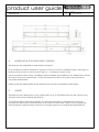
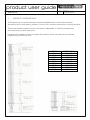
product user guide
title:
issue:
Superprop
1.
5
issue date:
August 2012
PRODUCT DESCRIPTION
The Superprop comprises double channels welded back to back with spacers
and which are connected in groups of four to form cruciform sections in varying lengths.
These are pinned together end to end and to adjustable or fixed head and base
units using four pins at each joint.
Modular twin header beams complete the system which can also be connected
together by pins end to end.
ASSEMBLY
SPA1
SPA2
SPA3
SPA4
SPA5
SPA6
SPA7
SPA8
SPA9
1
WEIGHT (KG)
344.45
452.24
276.52
187.43
108.05
197.71
366.43
803.86
12166.49
product user guide
title:
issue:
Superprop
2.
5
issue date:
August 2012
HANDLING & STACKING AND LOADING
Superprops are supplied as assemblies as listed.
Prop bodies should be stacked in groups of three or less on suitable timber dunnage on
level ground and no more than two high, ie. a maximum stack of six.
Care should be taken when handling head and base assemblies as the adjustment screw
is loose in the prop base/head. A stop screwed into the end of the screw prevents
complete withdrawal.
Head and base assemblies should always be stored and handled individually.
3.
USAGE
Superprops are designed to carry axial loads of up to 2500kN and may be used an any
vertical, horizontal or raking application.
The safe working load is dependant on the crew extension, unbraced prop length,
horizontal loads and load eccentricity and reference should b made to the Superprop
Data Sheets for safe working load's prop length graphs for the different applications.
2
product user guide
title:
issue:
Superprop
4.
5
issue date:
August 2012
ASSEMBLY AND INSTALLATION
Superprops are delivered to site pre-assembled in modules which are then pinned
together to form the required length and prop type. Should AB51 panel pins be used
then AB 205 circlip pliers will be required.
M24 bolts are used for the fixing of bracing panels to the props only requiring
36mm AF spanner.
Assembly should take place on a clean flat area adjacent to their final location.
A typical erection crew should comprise a foreman and three operatives competent in
basic structural steelwork erection.
Superprops should be lifted and erected by a crane in preference to say a rough terrain
forklift although the latter may be required in limited headroom locations.
In view of the many and varied Superprop applications it is strongly recommended that
method statements are prepared and the risks assessed for each contract.
MSSL will advise on all technical and erection matters if required.
4.1
5OTe Plain Ram Jack
As the jack does not incorporate a screw collar we strongly recommend a separate
means of mechanical support, either a screw jack or packing, is provided to support the
load in the event of a sudden loss of pressure within the hydraulic circuit.
4.2
Reading the Pressure Gauge
All Mabey Support Systems pressure gauges read in pounds per square inch (PSI).
Some gauges have dual scales reading in PSI and tonnes or bar.
The tonnes scales should not be used.
Mabey Support Systems have a range of pressure gauges with different full-scale readings
(for example 4,000 PSI, 7000 PSI and 10,000 PSI). Unless specifically requested the gauge
supplied with the jacks will read to 10,000 PSI.
When more than one jack is connected to a pressure gauge via a manifold, the gauge will
show the force in each jack.
Example: 4 screw ram jacks connected to a pressure gauge reading 10,000 PSI means
each jacks is carrying 539kN, ie. 2156 kN total.
3