1
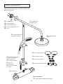
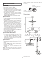
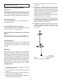
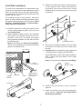
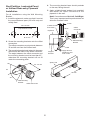
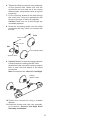
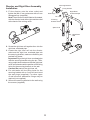
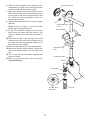
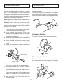
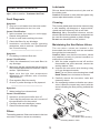
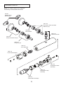
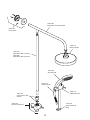
Mira atom ERD
Thermostatic Bar Valve
Installation & User Guide
These instructions must be left with the user.
1
Contents
Introduction
Introduction
2
Guarantee
2
Recommended Usage
2
Patents and Design Registration
3
Safety Warnings
3
Pack Contents
4
Specifications
5
Pressures
5
Temperatures
5
Thermostatic Shut-down
5
Connections
5
Dimensions
5
Installation Thank you for purchasing a quality Mira product. To
enjoy the full potential of your new product, please
take time to read this guide thoroughly, having
done so, keep it handy for future reference.
The Mira Atom thermostatic bar valve is a
thermostatic shower control designed for wall
mount installations.
The thermostatic bar valve has two knobs, one
knob controls the flow and the other knob controls
the temperature.
The Mira Atom ERD is supplied with a deluge
head, rigid riser and divertor assembly, in addition
to a single mode showerhead and shower fittings
kit.
The thermostatic bar valve incorporates a wax
capsule temperature sensing unit, which provides
an almost immediate response to changes in
pressures or temperature of the incoming water
supplies, to maintain the selected temperature. An
adjustable maximum temperature stop is provided
which limits the temperature to a safe level.
Inlet filters are fitted to protect the thermostatic
cartridge.
6
Suitable Plumbing Systems
6
General
6
Solid Wall Installation
7
Stud Partition, Laminated Panel,
or Unfixed Rear-entry Pipework
Installation
Divertor and Rigid Riser Assembly
Installation
Commissioning
Maximum Temperature Setting
Operation
8
10
12
12
Adjusting the Flow
12
Operating the Divertor
12
Fault Diagnosis
Spare Parts
13
13
14
Accessories
16
Notes
17
Customer Service
For domestic installations, Mira Showers
guarantee the Mira Atom against any defect in
materials or workmanship for a period of three
years from the date of purchase (shower fittings
for one year).
For non-domestic installations, Mira Showers
guarantee the Mira Atom against any defect in
materials or workmanship for a period of one year
from the date of purchase.
For terms and conditions refer to the back cover
of this guide.
12
Adjusting the Temperature
User Maintenance
Guarantee
12
Recommended Usage
Back Page
Application
If you experience any difficulty with the
installation or operation of your new
thermostatic mixer, please refer to ‘Fault
Diagnosis’, before contacting Kohler Mira Ltd.
Our contact details can be found on the back
cover of this guide.
2
Valve with
Fittings
Domestic
ü
Light Commercial
ü
Heavy Commercial
û
Healthcare
û
Patents and Design Registration
Safety Warnings
Patents
GB:
2 407 138
The function of a thermostatic mixing valve is to
deliver water consistently at a safe temperature. In
keeping with every other mechanism, it cannot be
considered as functionally infallible and as such,
cannot totally replace a supervisor’s vigilance
where that is necessary. Provided it is installed,
commissioned, operated and maintained within
manufacturers recommendations, the risk
of failure, if not eliminated, is reduced to the
minimum achievable.
Mira thermostatic mixers are precision engineered
and should give continued safe and controlled
performance, provided:
1.They are installed, commissioned, operated
and maintained in accordance with the
manufacturer’s recommendations.
2. Periodic attention is given, when necessary,
to maintain the product in good functional
order.
Caution!
1.Read all of these instructions.
2.Retain this guide for later use.
3. Pass on this guide in the event of change of
ownership of the installation site.
4. Follow all warnings, cautions and instructions
contained in this guide.
5. Anyone who may have difficulty understanding
or operating the controls of any shower should
be attended whilst showering. Particular
consideration should be given to the young,
the elderly, the infirm or anyone inexperienced
in the correct operation of the controls.
6. Rapid/Excessive movement of the flow and/
or temperature control levers may result in
momentary unstable blend temperatures.
7.Care is required when adjusting flow or
temperature, make sure that the temperature
has stabilised.
8. When this product has reached the end of its
serviceable life, it should be disposed of in a
safe manner, in accordance with current local
authority recycling, or waste disposal policy.
Design Registration
000793401-0001-0004
3
Pack Contents
Tick the appropriate boxes to familiarise yourself
with the part names and to confirm that all of the
parts are included.
q 2 x Wall Plugs
q 2 x Fixing Screws
q 1 x Securing Bracket
q 1 x Securing Bracket Cover
q 1 x Pin
q 1 x Rigid Riser
Overhead Pipe
q 1 x Rigid Riser Rail
q 1 x Deluge Head
(supplied in 2 parts)
& Seal
q 2 x Concealing Plates
q 2 x Washers / Filters
q 1 x Divertor Assembly
(inc Nut, Olive & M4 x
5 mm Grubscrew)
q 2 x Inlet Connectors
q 1 x EV Fittings Kit
q 1 x 2 mm
q 2 x Wall Mounting Brackets
Hexagonal Key
q 1 x Flow Regulator
(12 L/Min)
q 1 x Mira Atom
Documentation
q 1 x Guarantee Registration Document
4
Offset connector (inlet centres are 150 mm
± 24 mm).
Specifications
Pressures
¾" BSP
Connection to Bar Valve
• Max Static Pressure: 10 Bar.
• Max Maintained Pressure: 5 Bar.
• Min Maintained Pressure: (Gas Water Heater):
•
1.0 Bar (for optimum performance supplies
should be nominally equal).
Min Maintained Pressure (Gravity System):
0.1 Bar (0.1 bar = 1 Metre head from cold tank
base to showerhead outlet).
Note! 0.25 Bar when running both outlets.
½" BSP
Connection to Pipework
Dimensions
Temperatures
• Close temperature control is provided between
20°C and 50°C.
• Optimum Thermostatic Control Range: 35°C
59
Ø70
100
•
•
1000
•
to 45°C (achieved with supplies of 15°C cold,
65°C hot and nominally equal pressures).
Recommended Hot Supply: 60°C to 65°C
(Note! The mixing valve can operate at
temperatures up to 85°C for short periods
without damage. However for safety reasons
it is recommended that the maximum hot water
temperature is limited to 65°C).
Minimum Differential between Hot Supply and
Outlet Temperature: 10°C.
Cold Water Range: 5°C - 25°C.
Thermostatic Shut-down
• For safety the thermostat will shut off the
100 Min to Wall
hot supply within 2 Seconds if the cold
supply fails (achieved only if the hot supply
temperature is greater than 10°C above the
set blend temperature).
150 ± 24
340
Connections
145
• Hot: Left (side nearest flow control), ½”  BSP
Male.
• Cold: Right (side nearest temperature
control), ½” BSP Male.
• Outlet: top, 15 mm compression from
190
divertor.
Note! This product does not allow for reversed
inlets and will deliver unstable temperatures if
fitted incorrectly.
Dimensions in mm
5
100 Min to Wall
80
5. Pipework dead-legs should be kept to a
minimum.
6.Decide on a suitable position for the mixer.
The position of the mixer and the shower
fittings must provide a minimum gap of 25 mm
between the spill-over level of the shower tray/
bath and the showerhead (refer to illustration).
This is to prevent back-siphonage.
Note! Only use shower fittings recommended
by the manufacturer or supplier.
7. All pipework must be checked for leaks before
the product installation is completed. The
product should be pressurised & the inlet &
outlet connections inspected.
8. Do Not overtighten grubscrews as product
damage may occur. Use hexagonal key
provided and hand tighten only, do not use
powertools.
Installation
Suitable Plumbing Systems
Gravity Fed:
The thermostatic mixer must be fed from a cold
water cistern (usually fitted in the loft space) and
a hot water cylinder (usually fitted in the airing
cupboard) providing nominally equal pressures.
Gas Heated System:
The thermostatic mixer can be installed with a
combination boiler.
Unvented Mains Pressure System:
The thermostatic mixer can be installed with an
unvented, stored hot water system.
Mains Pressurised Instantaneous Hot Water
System:
The thermostatic mixer can be installed with
systems of this type with balanced pressures.
Pumped System:
The thermostatic mixer can be installed with
an inlet pump (twin impeller). The pump must
be installed on the floor next to the hot water
cylinder.
General
Installation must be carried out in accordance
with these instructions, and must be conducted by
designated, qualified and competent personnel.
The installation must comply with the “Water
Supply Regulations 1999 (Water Fittings)” or any
particular regulations and practices, specified by
the local water company or water undertakers.
Note! Make sure that all site requirements
correspond to the information given in section:
‘Specifications’.
25 mm
Spill Over
Level
1. The mixer must not be installed in an area
where it may freeze.
2. For stud partitions alternative fixings may be
required.
3. Isolating valves must be installed close to the
mixer for ease of maintenance.
4. Pipework must be rigidly supported and avoid
any strain on the connections.
6
Solid Wall Installation
3.Tighten the offset connectors using a spanner
on the spanner flats. Make sure that the
connectors are level and set at the correct
distance apart, using the bar valve as a guide
to spacing.
For solid wall installations the thermostatic bar
valve can be supported by the pipework provided
that it is securely fixed to the wall. Alternatively
for unfixed rear entry pipework the wall mounting
bracket can be used.
For installation onto a stud partition, laminated
panel, or onto unfixed rear‑entry pipework (using
the wall mounting bracket) refer to section: ‘Stud
Partition, Laminated Panel, or Unfixed Rearentry Pipework Installation’.
150 ± 24 mm
Cold
Spanner Flats
1. Install the pipework, making sure that it is set
at the correct distance apart (150 ± 24 mm)
and solidly fixed.
2.Apply suitable thread sealant (not supplied)
and attach the offset connectors to the
pipework in the wall. The offset connectors
must protrude between 35 and 40 mm from
the finished wall.
Note! Connections are: Hot-Left, Cold-Right.
This is very important as this product does not
allow for reversed inlets.
Hot
Concealing Plates
4.Screw the concealing plates onto the offset
connectors until they come into contact with
the wall.
5. Caution! Make sure that the supply pipework
is flushed before installing the Bar Valve.
Assemble the bar valve with a sealing washer/
filter in each inlet and attach to the offset
connectors.
Note! Connections are: Hot-Left, Cold-Right.
35 - 40 mm
½" BSP Female
Connection
Offset
Connector
Sealing
Washer / Filter
Tile
Support
Bracket
Pipework
Wall
Apply Silicone
Sealant to seal
hole in wall
Spirit Level
6.Tighten the connections using a suitable
spanner.
7. Install the divertor and rigid riser assembly,
go to section: ‘Divertor and Rigid Riser
Assembly Installation’.
150 mm
7
Stud Partition, Laminated Panel,
or Unfixed Rear-entry Pipework
Installation
4.The mounting bracket boss should protrude
to the rear, facing the wall.
5.Apply suitable thread sealant (not supplied)
and attach the offset connectors to the
pipework in the wall.
Note! Connections are: Hot-Left, Cold-Right.
This is very important as this product does not
allow for reversed inlets.
For all installations using the Wall Mounting
Bracket:
1. Install the pipework, make sure that it is set at
the correct distance apart (150 ± 24 mm) and
solidly fixed.
10 mm
150 ± 24 mm
½" BSP Female
Connection
Pipe Centres in Wall
Pipework
Offset
Connector
Boss
Ø 27 mm
Wall Mounting
Bracket
2.Screw the mounting brackets onto the offset
connectors.
The offset connectors must protrude between
35 and 40 mm from the finished wall.
3. The mounting bracket must extend in the same
direction as the offset of the offset connector.
The angle between the offset connector and
the mounting bracket must be less than 45°,
otherwise the mounting bracket will not fit
under the concealing plate.
Wall
Support
Bracket
Apply Silicone
Sealant to seal
hole in wall
Spirit Level
35 - 40 mm
45°
150 mm
45°
Wall Mounting
Bracket
Offset Connector
8
6.Tighten the offset connectors using a spanner
on the spanner flats. Make sure that the
connectors are level and set at the correct
distance apart, using the bar valve as a guide
to spacing.
7. Fix the mounting bracket to the wall through
the small hole, using the appropriate wall
fixings for the type of wall (not supplied).
Caution! Take care not to drill though any
concealed pipework.
8.Screw the concealing plates onto the offset
connectors until they come into contact with
the wall.
Cold
150 ± 24 mm
35 - 40 mm
Hot
Concealing Plates
Spanner Flats
9. Caution! Make sure that the supply pipework
is flushed before installing the Bar Valve.
Assemble the bar valve with a sealing washer/
filter in each inlet and attach to the offset
connectors.
Note! Connections are: Hot-Left, Cold-Right.
Sealing
Washer / Filter
10.Tighten the connections using a suitable
spanner.
11.Install the divertor and rigid riser assembly,
go to section: ‘Divertor and Rigid Riser
Assembly Installation’.
9
Divertor and Rigid Riser Assembly
Installation
Securing Bracket
Fixing Screws
1. Fit the divertor onto the mixer outlet and
tighten the M4 x 5 mm grubscrew with a 2 mm
hexagonal key (supplied)
Note! The divertor must be fitted as illustrated,
with the divertor knob at the right and the outlet
at the back of the mixing valve.
Rigid Riser
Overhead Pipe
Wall Plugs
Pin
Securing
Bracket Cover
Spirit Level
Rigid Riser
Rail
2. Screw the rigid riser rail together then into the
rigid riser overhead pipe.
3.Locate the rigid riser rail into the divertor
outlet and the rigid riser overhead pipe into
the securing bracket, make sure that they are
pushed fully home.
Important! Align the rigid riser overhead pipe
with the securing bracket using the pin. Then,
using a spirit level make sure that the rigid riser
rail is vertical and mark the position of the fixing
holes for the securing bracket on the wall.
Caution! Do not cut the rigid riser rail.
4. For solid walls drill the fixing holes for the
securing bracket with a 6 mm drill and insert
the wall plugs (supplied). For other types
of wall structure alternative fixings may be
required (not supplied).
5. Secure the securing bracket to the wall using
the screws (supplied).
10
6. Slide the clamp bracket, hose retaining ring,
compression nut and olive onto the rigid riser
rail and locate into the divertor outlet.
7. Make sure that the securing bracket cover is
fitted onto the rigid riser overhead pipe, then
fix the pipe to the securing bracket with the
pin. Screw the securing bracket cover over
the securing bracket.
8. Tighten the compression nut using a suitable
spanner.
Note! Hold the divertor in position whilst
tightening the compression nut.
9. Fit the 12 L/Min flow regulator into the hose
then screw the hose onto the outlet of the
divertor, making sure that the hose seal is
fitted.
10.P ass the flexible hose through the hose
retaining ring and screw the remaining end of
the hose onto the showerhead making sure
that the hose seal is fitted.
11.Place the showerhead in the clamp bracket.
18.Make sure that the hose washer is fitted and
screw the deluge head onto the rigid riser
arm.
12.Turn on the hot and cold water supplies and
check for leaks.
13.Before using the shower, refer to section:
‘Commissioning’.
Securing Bracket
Pin
Securing Bracket
Cover
Clamp Bracket
Hose Retaining
Ring
Compression Nut
Olive
Hose Seal
12 L/Min Flow
Regulator
11
Hose
Commissioning
Operation
Maximum Temperature Setting
Adjusting the Temperature
Before using the shower the maximum temperature
must be checked to make sure that it is at a safe
level. It has been preset to a safe showering
temperature under ideal conditions at the factory,
appropriate for most systems. However, site
conditions and personal preference may make it
necessary to reset this temperature.
Note! Make sure that the hot water temperature is
at least 55°C and that there is sufficient supply.
Caution! Before testing the mixer, make sure
that the hot and cold water is flowing correctly by
exercising the temperature selector knob between
the cold and hot stops.
1.Turn the temperature selector knob to position
7 and test that the temperature of the water
from the shower outlet is hot enough.
2. If not, depress the override button and
carefully rotate towards position 9. If the water
temperature is still not hot enough complete
the following procedure.
3.Rotate the temperature selector knob back to
position 7.
4. Using a suitable screwdriver carefully prise
off the concealing cap and unscrew the fixing
screw.
5. Pull off the temperature selector knob without
disturbing the stop assembly.
The temperature is controlled by rotating the
temperature knob.
For safety reasons, the temperature is limited by
an override stop. To obtain a higher temperature,
press the override button on the temperature knob
and continue to rotate.
+
Adjusting the Flow
The flow is controlled by rotating the flow knob.
ON
Temperature
Selector Knob
OFF
Operating the Divertor
Concealing Cap
The flow is switched between the deluge head,
the showerhead and both together by rotating
the divertor knob.
Fixing Screw
6.Replace the temperature selector knob so that
the 6 mark is in line with the stop assembly.
7.Rotate the temperature selector knob to
position 7, wait for the water to stabilise and
test that the temperature of the water from the
shower outlet is hot enough.
If the water temperature is still not hot enough
repeat the procedure until a maximum safe
temperature is achieved at position 9.
8. Refit and tighten the fixing screw, refit the
concealing cap.
12
Lubricants
User Maintenance
Silicone based lubricants must only be used on
the rubber seals.
Caution! Oil based or other lubricant types may
cause rapid deterioration of seals.
If you require a Mira trained service engineer or
agent, refer to section: ‘Customer Services’.
Fault Diagnosis
Cleaning
Symptom:
Only hot or cold water from the mixer outlet.
Outlet temperature too hot / too cold.
•
•
The chrome plated parts should be cleaned using
a mild washing up detergent or soap solution,
rinsed and then wiped dry with a soft cloth.
Warning! Many household cleaners contain
abrasive and chemical substances, and should not
be used for cleaning plated or plastic fittings.
Do not use descalents on this product.
Cause / Rectification:
Inlets reversed (hot supply to cold supply).
Rework inlet pipework.
No hot or cold water reaching the mixer.
Check the filters for any blockage.
Installation conditions outside operating
parameters, refer to sections: ‘Specifications’
and ‘Commissioning’.
•
•
•
•
Maintaining the Non-Return Valves
The non-return valves are located in the
thermostatic bar valve body, and are accessible
through the inlet connectors.
Caution! Make sure that the non-return valves
are installed correctly to prevent crossflow or
malfunction of the valve.
1. With the water supplies turned off and the
thermostatic bar valve removed, remove the
sealing washer / filter.
2. Unscrew the non-return valve housing using
a 12 mm hexagonal wrench.
Note! The non-return valve housing has a Left
Hand Thread, turn clockwise to unscrew.
3. Carefully remove the non-return valve and
clean any debris.
4.On re assembly make sure that the non-return
valve is fitted the correct way round (with the
arrow indicating the flow pointing towards the
valve).
—————————————
Symptom:
Fluctuating or reduced flow rate.
•
Cause / Rectification:
Check the showerhead, hose and filters for
any blockage.
Make sure that the maintained inlet pressures
are nominally balanced and sufficient, refer to
section: ‘Specifications’.
Make sure that the inlet temperature
differentials are sufficient, refer to section:
‘Specifications’.
Flow regulator fitted incorrectly.
Air lock or partial blockage in the pipework.
•
•
•
•
•
—————————————
Symptom:
Water leaking from showerhead.
•
Cause / Rectification:
Normal for a short period after shut off.
Check that the pressures are not in excess of
the specifications for the product.
Cartridge inlet seals damaged, renew.
Renew the thermostatic cartridge.
•
•
•
•
Filters
Non-Return
Valve
The sealing washers / filters are located in the inlet
connector. Clean or renew as necessary.
Inlet Connector /
Non‑Return Valve Housing
Sealing Washer / Filter
13
Spare Parts
Note! All spare parts are supplied
individually unless stated otherwise.
456.29
Wall Mounting
Bracket (x2)
1663.113
Non Return Valve and Filter
Washers (x2)
1630.049
Filter Washer
1663.170
Outlet Connector
1630.041
Offset Connector Kit (x2)
1663.311
Long Inlet (x2)
1663.117
Flow Cartridge
1663.118
Flow Knob Assembly
1663.116
Temperature Knob
Assembly
1663.115
Temperature Stop
Assembly
1663.114
Thermostatic Cartridge
14
1663.289
Rigid Riser Overhead Pipe
1660.162
Fixing Pack
1660.161
Deluge Head
1660.163
Rigid Riser Rail (1 Piece)
1660.289
Rigid Riser Rail (2 Piece)
1663.190
Showerhead
1603.137
Flexible Hose
1660.172
Clamp Bracket
1660.178
Compression Nut
& Olive
1660.165
Divertor Assembly
1595.073
Hose Retaining
Ring
15
accessories
ACCESSORIES
Genuine mira accessories can be purchased direct from customers services (our contact details can
be found on the back cover of this guide) or from approved stockists or merchants.
Eco Showerhead
White - 2.1668.001
Chrome - 2.1668.002
the eco shower head gives
you an invigorating shower, but
reduces water consumption and
heating costs.
Everclear Showerhead
White - 2.1616.030
Chrome - 2.1616.031
mira's new everclear range has
been specially designed for hard
water areas and reduces the risk
of lime scale build up.
Logic Showerhead Holder
White - 2.1605.149
White/Chrome - 2.1605.150
an alternative to the traditional
slide bar. often a useful addition
when positioned for the smaller
members of the family.
Wall Mounted Soap Dish
White - 1.1540.278
Chrome - 1.1540.279
Wall mounted for use anywhere in,
or outside the showering area.
BarValveFixingKit
Chrome - 2.1663.017
A fixing kit designed to make the
installation of bar valves easier
and more secure than traditional
'Z' connectors.
MiraBarValveFixingElbows
Chrome - 2.1712.002
designed to allow any bar valve
with 3/4” female connections to
be easily installed onto exposed,
rising or falling inlet supply
pipework.
Shower Seat
White - 2.1536.128
White/Chrome - 2.1536.129
For use in or out of the showering
area. Folds up when not in use.
maximum User Weight - 127 kg
(20 stone) Note! must be installed
onto a solid wall.
Premium Shower Seat
White/Chrome - 2.1731.001
Grey/Chrome - 2.1731.002
stylish, slim-line and robust
shower seat for use in or outside
of the shower area. Folds up when
not in use. maximum User Weight
- 150 kg (23.5 stone) Note! must
be installed onto a solid wall.
16
notes
17
notes
18
notes
19
Customer Service
Guarantee
your product has the benefit of our manufacturer’s
guarantee which starts from the date of purchase.
to activate this guarantee, please return your completed
registration card, visit our website or free phone 0800
0731248 within 30 days of purchase (UK only).
Within the guarantee period we will resolve defects in
materials or workmanship, free of charge, by repairing or
replacing parts or product as we may choose.
This guarantee is in addition to your statutory rights
and is subject to the following conditions:
● The product must be installed and maintained in
accordance with the instructions given in this user
guide.
● Servicing must only be undertaken by us or our
appointed representative. Note! if a service visit
is required the product must be fully installed and
connected to services.
● Repair under this guarantee does not extend the original
expiry date. the guarantee on any replacement parts
or product ends at the original expiry date.
● For shower fittings or consumable items we reserve
the right to supply replacement parts only.
The guarantee does not cover:
● Call out charges for non product faults (such as
damage or performance issues arising from incorrect
installation, improper use, lack of maintenance, build up
of limescale, frost damage, corrosion, system debris or
blocked filters) or where no fault has been found with
the product.
● Water or electrical supply, waste and isolation issues.
● Compensation for loss of use of the product or
consequential loss of any kind.
● Damage or defects caused if the product is repaired
or modified by persons not authorised by us or our
appointed representative.
● Routine maintenance or replacement parts to comply
with the requirements of the tmV 2 or tmV 3 healthcare
schemes.
Helpdesk Service
our dedicated customer services team is comprehensively
trained and can offer help and advice, spare parts,
accessories or a service visit. We will need you to have your
model name or number, power rating (if applicable) and date
of purchase. as part of our quality and training programme
calls may be recorded or monitored.
Mira Showers Website (www.mirashowers.co.uk)
From our website you can register your guarantee,
download additional user guides, diagnose faults, purchase
our full range of accessories and popular spares, refer to
our FaQ’s and request a service visit.
Spares and Accessories
We maintain extensive stocks of genuine spares and
accessories and aim to provide support throughout the
product’s expected life. Payment can be made by phone
at time of order using most major credit or debit cards and
we aim to despatch orders within two working days. Items
purchased from us are guaranteed for 12 months from date
of purchase. For safety reasons spares exposed to mains
voltages should only be fitted by competent persons.
Returns – items can be returned within one month of date of
purchase, providing that they are in good condition and the
packaging is unopened. Please obtain authorisation from
our customer services team before return. We reserve the
right to apply a 15% restocking charge.
Service / Repairs
We have a nationwide team of service technicians who can
carry out all service or repair work to your product within the
guarantee period and beyond. you have the assurance of a
fully trained mira technician, genuine mira spare parts and
a 12 month guarantee on any chargeable work done.
Payment should be made directly to the service technician
who will accept most major credit or debit cards.
To Contact Us
UK
Telephone: 0844 571 5000
mon to Fri 8:00 am - 5:30 pm, sat 8:30 am - 3:30 pm
e-mail: [email protected]
If your product does not function correctly when you first Fax: 01242 282595
use it, contact your installer to check that it is installed By Post: mira customer services dept, cromwell road,
and commissioned in accordance with the instructions in cheltenham, Gloucestershire, Gl52 5eP
this manual.
should this not resolve the issue, contact our customer Eire
services team who will offer you or your installer advice and Telephone: 01 459 1344
if applicable arrange for a service technician to call.
mon to Fri 9:00 am - 5:00 pm
If the performance of your product declines, check in this e-mail: [email protected]
manual to see if simple home maintenance is required. If Fax: dublin 01 459 2329
you require further assistance call our customer services
By Post: modern Plant ltd (dublin),
team.
otter house, naas road, clondalkin, dublin 22
What to do if something goes wrong
ExtendedGuarantees
a selection of protection plans are available that
enable you to cover repair bills for the life of your policy
(excludes eire). ring 01922 471763 for more details.
mira is a registered trade mark of
Kohler mira limited.
the company reserves the right to alter
product specifications without notice.
1098814-W2-F (H04B) (1663)
UKAS
20
© Kohler Mira Limited, April 2010