1
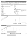
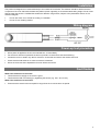
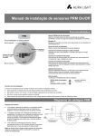
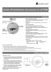
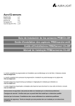
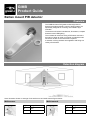
GIMB Product Guide Batten mount PIR detector Overview The GIMB miniature PIR (passive infrared) presence detector provides automatic control of lighting loads. It is specifically designed for mounting onto a batten style luminaire. The detector will switch incandescent, fluorescent, compact fluorescent and LED lighting. The unit detects movement using a PIR sensor and turns the load on. When an area is no longer occupied the load will switch off after a 10 minute time out period. A selection of fixing washers are supplied to aid fixing to a variety of luminaires. Detection diagram Note: illustration shows an average of the walk across and walk towards figures below. Walk across Walk towards Height Range Diameter Height Range Diameter 7m 16m 7m 10m 2.8m 9m 2.8m 5m Installation Do not grip unit at the lens end. Hold the square body near the threaded end when installing and tightening the nut. Care must be taken to prevent damage to the lens and surrounding IP seal. Components Part Mounting hole without key Quantity Supplied IP Spacer with silicone coating 1 Silicone washer 1 5º washer 1 Mounting hole with key Note. Key to be at top of sensor. 5º spacer 1 M20 nut 1 Standard luminaire fitting IP luminaire fitting Important Ensure that the Silicone washer and/or the IP spacer are used to ensure IP rating. Note. Use the 5º spacers where the luminaire housing has a draft angle. 2 Installation The product is designed to be mounted directly to the outside of a luminaire. The detector should be sited so that the occupants of the room fall inside the detection pattern (shown opposite), at a recommended ceiling height of 2.8m. Note that the lower the sensor is installed the smaller the detection range will be, subject to the parameters shown on the detection diagram. Do not site within 1m of forced air heating or ventilation.. Do not fix to a vibrating surface. Wiring diagram Power-up test procedure When power is applied to the unit, the load will turn on immediately. For the first 5 minutes of operation the time out period is 10 seconds to aid commissioning. Vacate the room or remain very still for more than 10 seconds and wait for the load to switch off. Check that the load switches on when movement is detected. When the 5 minutes have elapsed the time out will be 10 minutes. Fault finding What if the load does not turn ON? Check that the live supply to the circuit is good. Check that the load is functioning by bypassing the sensor (e.g. link L and L/ Out). What if the load does not turn OFF? Ensure that the area is left unoccupied for longer than the 10 minute time out period. 3 Technical data Dimensions Weight Supply Voltage Frequency Maximum Switching Load Power consumption Cable specification Temperature Humidity Material Type IP rating Compliance See diagrams opposite. 0.10kg 230VAC +/- 10% 50Hz 2 Amps fluorescent and incandescent lighting. 2 Amps compact fluorescent lighting. 2 Amps low energy lighting. 2 Amps low voltage lighting (switch primary of transformer). Switch SON lighting loads via a contactor. On 799mW, Off 807mW 1m 1/1.13 solid core cable 105ºC -10ºC to 50ºC 5 to 95% non-condensing Flame retardant ABS/PC Class 2 IP65 EMC-2004/108/EC LVD-2006/95/EC IMPORTANT NOTICE! This device should be installed by a qualified electrician in accordance with the latest edition of the IEE Wiring Regulations and any applicable Building Regulations. FM 45789 EMS 534520 Due to our policy of continual product improvement CP Electronics reserves the right to alter the specification of this product without prior notice. 4 C.P. Electronics Ltd Brent Crescent London NW10 7XR United Kingdom Tel: + 44 (0) 333 900 0671 Fax: + 44 (0) 333 900 0674 www.green-iswitches.co.uk [email protected] Ref: #WD639 Issue 2