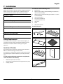
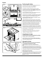
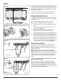
1
900S Induction User Guide Installation & Service Instructions ArtNo.000-0008 Falcon logo shaded U109999-04 Contents 1. 2. 3. Before You Start... 1 Installation 17 Installation and Maintenance 1 Dear Installer 17 Peculiar Smells 1 Safety Requirements 17 Ventilation 1 Location of Cooker 17 Personal Safety 1 Positioning the Cooker 18 Hob Care 2 Unpacking the Cooker 18 Cooker Care 2 Moving the Cooker 18 Cleaning 2 Completing the Move 19 Overview 3 Fitting the Flue Grille 19 The Hob 3 Levelling 19 The Multi-function Oven 6 Fitting a Stability Bracket 20 Energy Saving Feature 8 Electrical Connection 20 Accessories 9 Repositioning the Cooker following Connection 21 Oven Light 10 Hob Check 21 Storage 10 Oven Check 21 11 Fitting the Plinth 21 Cooking with a Multi-function Oven 11 Refitting the Drawer 21 General Oven Tips 11 Refitting the Oven Door 21 Customer Care 21 Cooking Tips 4. Cooking Table 12 5. Cleaning Your Cooker 13 6. 7. 8. Circuit Diagrams 22 9. Technical Data 24 Hob 13 Control Panel and Oven Doors 14 Cleaning Table 14 If you have a problem 25 15 Notes 25 Out of Warranty 25 Spare Parts 25 Troubleshooting 10. Warranty/After Sales Service 25 English 1. Before You Start... DocNo.015-0301 - Introduction - Induction cooker implanted insulin pump and are concerned please consult your doctor for medical advice. Thank you for buying a Falcon cooker. It should give you many years of trouble-free cooking if installed and operated correctly. It is important that you read this section before you start, particularly if you have not used an induction cooker before. This appliance is designed for domestic cooking only. Using it for any other purpose could invalidate any warranty or liability claim. In particular, the oven should NOT be used for heating the kitchen – besides invalidating claims this wastes fuel and may overheat the control knobs. Installation and Maintenance In the UK the electrical installation should be in accordance with BS 7671. Otherwise, all installations must be in accordance with the relevant instructions in this booklet, with the relevant national and local regulations, and with the local electricity supply companies’ requirements. This appliance is not intended for use by persons (including children) with reduced physical, sensory or mental capabilities, or lack of experience and knowledge, unless they have been given supervision or instruction concerning use of the appliance by a person responsible for their safety. Children should be supervised to ensure that they do not play with the appliance. DO NOT use a steam cleaner to clean the cooker. Accessible parts will become hot during use and will retain heat even after you have stopped cooking. Keep babies and children away from the cooker and never wear loose-fitting or hanging clothes while the appliance is in use. Always be certain that the controls are in the OFF position when the oven is not in use, and before attempting to clean the cooker. Take care when touching the marked cooking areas of the hob. When the oven is on, DO NOT leave the oven door open for longer than necessary, otherwise the control knobs may become very hot. Make sure that the cooker is wired in and switched on. The hob control display will flash for about 2 seconds during first power setting – this is normal. The cooker should be serviced only by a qualified service engineer, and only approved spare parts should be used. Always allow the cooker to cool and then switch it off at the mains before cleaning or carrying out any maintenance work, unless specified otherwise in this guide. Peculiar Smells When you first use your cooker it may give off a slight odour. This should stop after a little use. When the hob is in use keep magnetic items, such as credit and debit cards, floppy disk, calculators, etc. away. Cooking high moisture content foods can create a ‘steam burst’ when the oven door is opened. When opening the oven stand well back and allow any steam to disperse. Before using for the first time, make sure that all packing materials have been removed and then, to dispel manufacturing odours, turn the ovens to 200°C and run for an hour. Make sure the room is well ventilated to the outside air (see ‘Ventilation’ below). People with respiratory or allergy problems should vacate the area for this brief period. Ventilation Always keep combustible materials, e.g. curtains, and flammable liquids a safe distance away from your cooker. The use of a cooking appliance results in the production of heat and moisture in the room in which it is installed. Therefore, ensure that the kitchen is well ventilated: keep natural ventilation holes open or install a powered cooker hood that vents outside. If you have several hotplates on, or use the cooker for a long time, open a window or turn on an extractor fan. Personal Safety Important information for pacemaker and implanted insulin pump users: The functions of this hob comply with the applicable European standards on electromagnetic interference. If you are fitted with a pacemaker or 1 DO NOT use harsh abrasive cleaners or sharp metal scrapers to clean the oven door glass since they can scratch the surface, which may result in shattering of the glass. DO NOT spray aerosols in the vicinity of the cooker while it is on. Use dry oven gloves when applicable – using damp gloves might result in steam burns when you touch a hot surface. Do not use a towel or other bulky cloth in place of a glove – it might catch fire if brought into contact with a hot surface. English NEVER operate the cooker with wet hands. DO NOT use aluminium foil to cover shelves, linings or the oven roof. NEVER heat unopened food containers. Pressure build up may make the containers burst and cause injury. Do not stand or rest heavy objects on the hob. Although the ceramic surface is very strong, a sharp blow or sharp falling object (e.g. a salt cellar) might cause the surface to crack or break. DO NOT use unstable saucepans. Always ensure that you position the handles away from the edge of the hotplate. Make sure to use adequately sized pans with flat bottoms that are large enough to cover the surface of the hotplate heating area. Using undersized pans will expose a portion of the hotplate surface to direct contact and may result in the ignition of clothing. DO NOT place anything between the base of the pan and the hob surface (e.g. asbestos mats, aluminium foil, Wok stand). Care should be taken that no water seeps into the appliance. Only certain types stainless steel, enamelled steel pans or cast iron pans with enamelled bases are suitable for induction hob cooking. The ceramic surface should be washed after use to prevent it from becoming scratched or dirty. However, you should clean the hob with caution as some cleaners can produce noxious fumes if applied to a hot surface. NEVER leave a chip pan unattended. Always heat fat slowly, and watch as it heats. Deep fry pans should be only one third full of fat. Filling the pan too full of fat can cause spill over when food is added. If you use a combination of oils or fats in frying, stir them together before heating, or as the fats melt. DO NOT use abrasive cleaners/pads, oven aerosols/pads or stain removers on the surface. We recommend that you avoid wiping any surface unit areas until they have cooled and the indicator light has gone off. Sugar spills are the exception to this (see ‘Cleaning your Cooker’). After cleaning, use a dry cloth or paper towel to remove any cleaning cream residue. Foods for frying should be as dry as possible. Frost on frozen foods or moisture on fresh foods can cause hot fat to bubble up and over the sides of the pan. Carefully watch for spills or overheating of foods when frying at high or medium high temperatures. Never try to move a pan of hot fat, especially a deep fat fryer. Wait until the fat is cool. Cooker Care Do not use the top of the flue (the slot along the back of the cooker) for warming plates, dishes, drying tea towels or softening butter. As steam can condense to water droplets on the cool outer trim of the oven, it may be necessary during cooking to wipe away any moisture with a soft cloth. This will also help to prevent soiling and discolouration of the oven exterior by cooking vapours. DO NOT use water on grease fires and never pick up a flaming pan. Turn off the controls and then smother a flaming pan on a surface unit by covering the pan completely with a well-fitting lid or baking tray. If available, use a multipurpose dry chemical or foam-type fire extinguisher. Cleaning In the interests of hygiene and safety, the cooker should be kept clean at all times as a build up in fats and other food stuff could result in a fire. This appliance is heavy so take care when moving it. Clean only the parts listed in this guide. Hob Care Clean with caution. If a wet sponge or cloth is used to wipe spills on a hot surface, be careful to avoid steam burns. Some cleansers can produce noxious fumes if applied to a hot surface. DO NOT use the hob surface as a cutting board. Do not leave utensils, foodstuffs or combustible items on the hob when it is not is use (e.g. tea towels, frying pans containing oil). DO NOT place plastic or aluminium foil, or plastic containers, on the hob. DO NOT leave the hob zones switched on unless being used for cooking. Should a crack appear in the surface, disconnect the appliance immediately from the supply and arrange for its repair. Always LIFT pans off the hob. Sliding pans may cause marks and scratches. Always turn the control to the OFF position before removing a pan. Never leave the hotplate unattended at high heat settings. Pans boiling over can cause smoking, and greasy spills may catch on fire. Use a deep fat thermometer whenever possible to prevent fat overheating beyond the smoking point. NEVER allow anyone to climb or stand on the hob. 2 English 2. Overview � Fig.2-1 � 100° 140° 180° 220° � � The Falcon induction cooker (Fig.2-1) has the following features: A. B. C. D. Fig.2-2 5 induction cooking zones A control panel A multi-function oven A storage drawer The Hob ArtNo.312-0004 Correct pans ceramic Use only pans that are suitable for induction hobs. We recommend stainless steel, enamelled steel pans or cast iron pans with enamelled bases. Note that some stainless steel pans are not suitable for use with an induction hob so please check carefully before purchasing any cookware. Pans made of copper, aluminium or ceramic are not suitable for use on an induction hob. The kind of pan you use and the quantity of food affects the setting required. Higher settings are required for larger quantities of food. Pots and pans should have thick, smooth, flat bottoms (Fig.2-2). This ensures the maximum heat transfer from the hob to the pan, making cooking quick and energy efficient. Never use a round-bottomed wok, even with a stand. 3 English The very best pans have bases that are very slightly curved up when cold (Fig.2-3). If you hold a ruler across the bottom you will see a small gap in the middle. When they heat up the metal expands and lies flat on the cooking surface. Fig.2-3 ArtNo.312-0005 Curved bottomed pan ceramic Make sure that the base of the pan is clean and dry to prevent any residue burning onto the hob panel. This also helps prevent scratches and deposits. Always use pans that are the same size as (or slightly larger than) the areas marked on the hob. Using a lid will help the contents boil more quickly. Fig.2-4 The induction hob comprises of five cooking zones containing induction elements with different ratings and diameters each with a pan detector and residual heat indicator, and a hob control display. � � � � � ArtNo.313-0003 110 Induction hob display ������������ Always take care before touching the surface, even when the hob is turned off. It may be hotter than you think! The hob control display (Fig.2-4) informs you of the following induction hob functions: H A L U P �������������������� ������������� Pan detector Residual heat indicator Automatic heat-up Child lock Low temperature setting Power boost setting ���������� ��� ��������� ��� Pan Detector, ������ ��� ���������� ��� IMPORTANT: After use, switch off the hob element by its control and DO NOT RELY on the pan detector. ArtNo.051-0002 - Min pan diameter ����������� ��� If a cooking area is switched on and there is no pan in place or if the pan is too small for the cooking area, then no heat will be generated. The symbol [ ] will appear on the hob control display; this is the “pan-missing symbol”. Place a pan of the correct size on the cooking area and the [ ] symbol will disappear and cooking can begin. After 10 minutes without detecting a pan the cooking zone will switch off automatically. Table 2-1 Table 2-1 shows the minimum pan sizes recommended for each cooking zone. Note: Using pans with a base diameter smaller than those recommended will result in a power reduction. Residual Heat Indicator, H After use, a cooking zone will remain hot for a while as heat dissipates. When a cooking zone is switched off the residual heat indicator symbol [H ], will appear in the display. This shows that the cooking zone temperature is above 60°C and may still cause burns. Once the temperature has dropped to below 60°C the [H ] will go out. Automatic Heat-up, A This function is available on all of the cooking areas. It allows rapid heating up of the element to bring the selected cooking zone up to temperature. Once the zone is at the required cooking temperature the power level will reduce automatically to the preset level. 4 English The function is selected by turning the control knob to the ‘A’ position. This can be selected by either turning the control knob momentarily anti-clockwise from the zero position or clockwise past the ‘9’ until the symbol [A ] is shown on the hob control display. Once the [A ] is displayed, turn the control knob to the level of your choice (1 to 9). The pan will heat up at 100% power for a specified time before the power is reduced to the level selected. ����������� ���������������������� ����������������� � ���� � ���� � ���� � ���� � ���� When the Automatic Heat-up function is activated, the hob control display will alternately flash between the [A ] setting and the chosen power level. � ���� � ���� Once the automatic heat-up time has ended the hob control display will stop flashing and will display the chosen power level. � �ArtNo.051-0001 - Induction power levels ���� ���� Table 2-2 The Automatic Heat-up function can be stopped by either turning the control knob back to the ‘0’ power setting or turning the control knob to the ‘9’ power setting. For your guidance Table 2-2 shows the time available at 100% power depending on the power level selected in the Automatic Heat-up mode. Child Lock, L To prevent the unwanted use of the hob, by children, it can be locked. This can only be activated when all the cooking zones are off. To lock the hob, turn together induction controls 2 and 4 simultaneously anti-clockwise for approximately 3 seconds until [L ] appears in the hob control display for all cooking areas. This will NOT affect the oven; it can still be used. To unlock the hob, turn controls 2 and 4 simultaneously anticlockwise until the [L ] symbol disappears. Low Temperature Setting, U Each cooking area is equipped with a Low Temperature Setting. Turn the control knob clockwise to between the 0 and the 1, until [U ] is displayed. This will maintain a temperature of around 65°C, which will keep food warm or water very gently simmering ready to cook vegetables or is useful for melting butter without it burning. The maximum time this setting can be used is 2 hours. To increase the heat, just turn the control knob to the required level. Power Boost Setting, P All of the induction cooking zones have Power Boost available, activated by turning the control knob clockwise until [P ] is shown on the hob control display. Power Boost allows additional power to be made available for each of the cooking areas. This is useful to bring a large pan of water to the boil quickly. The Power Boost function operates for a maximum of 10 minutes on each zone, after which the power is automatically reduced to setting 9. When using the Power Boost function, the cooking areas are paired. 5 English Fig.2-5 shows the hob layout. Areas A and B are paired together as are areas D and E. The centre area C runs independently, regardless of the use of other cooking areas. Fig.2-5 ������� This means when using area A on power boost and then switching area B to power boost as well, then area A will have its power slightly reduced. The last one of the pair switched to power boost takes priority. Areas D and E work in the same way. � � � ArtNo.314-0014 Induction zone identifiers � � This is a built in safety device. Deactivate the Power Boost function by turning the control knob to a lower setting. � Induction The Multi-function Oven � Fig.2-6 The oven is a multi-function oven (Fig.2-6). As well as the oven fan and fan element, it is fitted with two extra heating elements, one visible in the top of the oven and the second under the oven base. Take care to avoid touching the top element and element deflector when placing or removing items from the oven. � The multifunction oven has 3 main cooking functions, fan, fan assisted and conventional cooking. These functions should be used to complete most of your cooking. ArtNo.326-0009 - Albertine SC - MF oven elements EU The browning element and base heat can be used in the latter part of the cooking process to fine tune the results to your particular requirements. � A - Grill Elements, B - Convection Elements, C - Base Heat Elements Use fanned grilling for all your grilling needs and defrost to safely thaw small items of frozen food. Function Use Table 2-3 gives a summary of the multi-function modes. Defrost To thaw small items in the oven without heat Fan oven A full cooking function, even heat throughout, great for baking Fanned grilling Grilling meat and fish with the door closed Note: The multi-function oven has many varied uses. We suggest you keep a careful eye on your cooking until you are familiar with each function (Fig.2-7). Remember – not all functions will be suitable for all food types. Fan assisted A full cooking function good for roasting and baking Conventional oven A full cooking function for roasting and baking in the lower half of the oven Browning element To brown and crisp cheese topped dishes Base heat To crisp up the bases of quiche, pizza or pastry Multi-function oven modes Defrost This function operates the fan(s) to circulate cold air ArtNo.061-0005 90 induction - 900S MF s only. No heat is applied. This enables- small items such as desserts, cream cakes and pieces of meat, fish and poultry to be defrosted. Defrosting in this way speeds up the process and protects the food from contamination. Pieces of meat, fish and poultry should be placed on a rack, over a tray to catch any drips. Be sure to wash the rack and tray after defrosting. Table 2-3 Defrost with the oven door closed. Defrosting should not be carried out in a warm oven. Large items, such as whole chickens and meat roasts should not be defrosted in this way. We recommend this be carried out in a refrigerator. Ensure that dairy foods, meat and poultry are completely defrosted before cooking. 6 English Fan oven This function operates the fans and the heating ArtNo.061-0005 - 90Aninduction - 900S MF symbols element around them. even heat is produced throughout the oven, allowing you to cook large amounts quickly. Convection oven cooking is particularly suitable for multirack cooking and is a good ‘all-round’ function. It may be necessary to reduce the temperature by approximately 10°C for recipes previously cooked in a conventional oven. Fig.2-7 � � � � ArtNo.061-0001 - 90 induction - 900S MF oven controls If you wish to preheat the oven, wait until the indicator light has gone out before inserting the food. � Fanned grilling This function operates the fan while the top element ArtNo.061-0005 induction - 900S MFless symbols is on. -It90 produces a more even, fierce heat than a conventional grill. For best results place the food to be grilled on the pan provided. Thick pieces of meat or fish are ideal for cooking in this way, as the circulated air reduces the fierceness of the heat from the grill. The oven door should be kept closed while cooking is in progress, so saving energy. You will also find that the food needs to be watched and turned less than for normal grilling. Preheat this function before cooking. � � A - Defrost, B - Fan Oven, C - Fanned Grilling, D - Fan Assisted Oven, E - Conventional Oven, F - Browning Element, G - Base Heat Fan assisted oven This function operates the fans, circulating air heated -0005 - 90 induction - 900S MF symbols by the elements at the top and the base of the oven. The combination of fan and conventional cooking (top and base heat) makes this function ideal for cooking large items that need thorough cooking, such as a large meat roast. It is also possible to bake on two racks at one time, although they will need to be changed over during the cooking time, as the heat at the top of the oven is greater than at the base, when using this function. Note: This is a fast, intensive form of cooking; keep an eye on the food cooking until you have become accustomed to this function. Conventional oven (top and base heat) This function combines the heat from the top and uction - 900S MFbase symbols elements. It is particularly suitable for roasting and baking pastry, cakes and biscuits. The exposed top element may cook some foods too quickly, so we recommend that the food be positioned in the lower half of the oven to cook. The oven temperature may also need to be lowered. Similar items being cooked will need to be swapped around for even cooking. Browning element This function uses the element in the top of the MF symbols oven only. It is a useful function for the browning or finishing of pasta dishes, vegetables in sauce and lasagne, the item to be browned being already hot before switching to the top element. 7 English Base heat This function uses the base element only. It will crisp up your pizza or quiche base or finish off cooking the base of a pastry case on a lower rack. It is also a gentle heat, good for slow cooking of casseroles in the middle of the oven or for plate warming. WARNING! Take great care- 90 when removing theMF divider NOT to ArtNo.061-0005 induction - 900S symbols scratch the inner glass door surface. Scratches in the glass can cause stress and may cause the door to fail. The Browning and Base heat functions are useful additions to your oven, giving you flexibility to finish off items to perfection. With use, you will soon realize how these functions can combine to extend your cooking skills. Fig.2-8 Energy Saving Feature The oven has a divider feature (Fig.2-8). When this is in place only one half of the oven is heated and only the right-hand side elements are used. This saves energy and is ideal for cooking most foods. When using the divider, condensation may appear in the left-hand oven – this is normal. ArtNo.281-0150 - Oven Divider For very large loads, or large dishes for special occasions then the divider can be removed. This brings into use the elements on the left-hand side as well as those on the right when a function is selected. ArtNo.062-0005 - Removing the divider (wrong) All oven functions are available in full and divided forms and shelves are provided for use in both forms. WARNING! Take great care when removing the divider NOT to scratch the inner glass door surface. Scratches in the glass can cause stress and may cause the door to fail. Removing the Divider Make sure the cooker is cool before attempting to remove the divider. Fully open the door and remove the oven shelves. When removing the divider, tilt it slightly upwards and grip the underside to prevent the metal base making contact with the door glass (Fig.2-9 and Fig.2-10). We recommend that you place a tea towel or similar on the door glass before removing the divider. This should prevent the door inner from scratching. Fig.2-9 ArtNo.062-0004 - Removing the divider (right) DO NOT place or slide metallic objects, including cookware, on the door glass as this may cause scratching and subsequent failure to occur. Fig.2-10 8 English Operating the Oven Fig.2-11 The Multi-function oven has two controls, a function selector and a temperature setting knob (Fig.2-11). Turn the function selector control to a cooking function. This is the Convection oven setting (Fig.2-12). Turn the oven temperature knob to the temperature you need. 100 ° 220 ° ° 140 180 ° ArtNo.061-0001 - 90 induction - 900S MF oven controls The oven heating light will glow until the oven has reached the temperature you selected. It will then cycle on and off during cooking as the oven maintains the selected temperature (Fig.2-13). Fig.2-12 Your oven has many varied uses. We suggest you keep a careful eye on your cooking until you are familiar with each function. Remember, not all functions will be suitable for all food types. Fig.2-13 ArtNo.061-0001 - 90 induction - 900S MF oven controls ArtNo.061-0001 - 90 induction - 900S MF oven controls 100 ° 220 Accessories Fig.2-14 ° 180 ° ° 140 Please remember that all ranges vary – temperatures in your new ovens may differ to those in your previous range. Fig.2-15 Oven racks Each oven is supplied with: ArtNo.326-0002 - Energy saving shelf • One full capacity shelf (Fig.2-14) • Two energy saving shelves (Fig.2-15) • One full capacity shelf with grill tray (Fig.2-16) • One pastry tray (Fig.2-17) • And one divider (Fig.2-18) Any shelf can be fitted in any of the positions. The oven shelves are retained when pulled forward but can be easily removed and refitted. Fig.2-16 Fig.2-17 ArtNo.326-0014 - Cradle rack (Falcon) To remove the shelf The shelf has a small recess on either side. To remove the shelf these must be in line with the shelf brackets (Fig.2-19). Lift and pull the shelf forward (Fig.2-20). Fig.2-18 ArtNo.331-0008 - 90SC grill pan & trivet Fig.2-19 ArtNo.280-0055 - Removing Shelf Detail Refitting the shelf Place the shelf in between two side shelf runners at the position you require (Fig.2-21). Slide back until it reaches the rear of the oven cavity. ArtNo.281-0028 - Albertine divider The shelves should not be fitted directly one above the other. When cooking on more than one shelf always leave at least one runner space between them. Fig.2-20 ArtNo.280-0056 - Removing Flat Side 9 Fig.2-21 ArtNo.280-0057 - Removing Flat Side 2 English Oven Light Fig.2-22 Press the button to turn the oven light on. If one of the oven lights fail, turn off the range circuit breaker before you change the bulb. See the ‘Troubleshooting’ section for details on how to change an oven light bulb (Fig.2-22). ArtNo.320-0023 Oven light USA Storage The bottom drawer is for storing oven trays and other cooking utensils. It can get very warm, so do not store anything in it that may melt or catch fire. Never store flammable materials in the drawer. This includes paper, plastic and cloth items, such as cookbooks, plasticware and towels, as well as flammable liquids. Do not store explosives, such as aerosol cans, on or near the appliance. Fig.2-23 Flammable materials may explode and result in fire or property damage. ArtNo.281-0138 - Drawer pulled out To remove the drawer, pull it fully forward (Fig.2-23). Lift up the ends of the plastic clips (one each side) to release the catches holding the drawer to the side runners and at the same time pull the drawer forward and away from the side runners (Fig.2-24). Fig.2-24 � For safety’s sake push the drawer runners back out of the way. To refit the drawer, pull the side rails fully out. Carefully move the drawer back between the rails and rest it on the side rails. At each side, hold the front of the drawer and pull the side rail forward so that the clips click into position, holding the drawer to the side rails (Fig.2-25). � ArtNo.341-0002 - 90 Drawer clip lift Fig.2-25 ArtNo.341-0003 - Drawer locking 10 English 3. Cooking Tips Cooking with a Multi-function Oven Remember: not all modes are suitable for all food types. The oven cooking times given are intended for a guide only. General Oven Tips The wire shelves should always be pushed firmly to the back of the oven. Baking trays with food cooking on them should be placed level with the front edge of the oven’s wire shelves. Other containers should be placed centrally. Keep all trays and containers away from the back of the oven, as overbrowning of the food may occur. When the oven is on, do not leave the door open for longer than necessary, otherwise the knobs may get very hot. • Always leave a ‘fingers width’ between dishes on the same shelf. This allows the heat to circulate freely around them. • To reduce fat splashing when you add vegetables to hot fat around a roast, dry them thoroughly or brush lightly with cooking oil. • Where dishes may boil and spill over during cooking, place them on a baking tray. • Sufficient heat rises out of the oven while cooking to warm plates in the grill compartment. • If you want to brown the base of a pastry dish, preheat the baking tray for 15 minutes before placing the dish in the centre of the tray. To help keep your oven clean, cover meat when roasting with foil or use a roasting bag. Brush vegetables with fat before placing around the meat. 11 English 4. Cooking Table DocNo.031-0004 - Cooking table - electric & fan single cavity The oven control settings and cooking times given in the table below are intended to be used AS A GUIDE ONLY. Individual tastes may require the temperature to be altered to provide a preferred result. Top Centre Food is cooked at lower temperature in a fan oven than in a conventional oven. When using recipes, reduce the fan oven temperature by 10°C and the cooking time by 5-10 minutes. The temperature in the fanned oven does not vary with height in the oven so you can use any shelf. Base °C position °C 160 C 150 200 C 190 160 C 150 200 C 190 160 C 150 200 C 190 160 C 150 20-25 minutes per 500g +20-25 minutes. 200 C 190 15-20 minutes per 500g +15-20 minutes. 160 C 150 20 minutes per 500g +20 minutes. 200 C 190 15 minutes per 500g +15 minutes. 160 C 150 25-30 minutes per 500g. 200 C 190 20 minutes per 500g. 140-150 C 130-140 220 C 210 Large tins 30-35 minutes; individual 10-20 minutes. Fillet 190 C/B 180 15-20 minutes. Whole 190 C/B 180 15-20 minutes per 500g. Steak 190 C/B 180 Steaks according to thickness. 140 C/B 130 45-50 minutes per 500g of mixture. Fruit 180 mm tin 150 C/B 140 2-2½ hours. Fruit 230 mm tin 150 C/B 140 Up to 3½ hours. Madeira 180 mm 160 C/B 150 80-90 minutes. Queen cakes 190 C/B 180 15-25 minutes. Scones 220 C/B 210 10-15 minutes. 180 mm tin 180 C/B 170 20-30 minutes. 210 mm tin 180 C/B 170 30-40 minutes. Shortcrust tarts 200 C/B 190 20-30 minutes on a preheated tray. Fruit pies 200 C/B 190 35-45 minutes. Tartlets 200 C/B 190 10-20 minutes according to size. Puff pastry 230 C/B 220 20-40 minutes according to size. Meringues 100 C/B 90 2-3 hours. Baked egg custard 160 C/B 150 45-60 minutes. 40-45 minutes. Meat Oven Shelf Positions ArtNo.050-0065 - Cooking table - electric & fan single cavity Conventional Oven Fan Oven Temperature Shelf Temperature Food ArtNo.050-0007 Oven shelf positions Approximate cooking time ArtNo.050-0001 Gas cooking table Beef (no bone) Lamb Pork Poultry Chicken Turkey Duck Casserole Yorkshire pudding 30-35 minutes per 500g +30-35 minutes. Thoroughly thaw frozen joints before cooking. Meat may be roasted at 20-25 minutes per 500g +20-25 minutes. 220°C (210°C for fan oven) and the 30-35 minutes per 500g +30-35 minutes. cooking time adjusted accordingly. 25-30 minutes per 500g +25-30 minutes. For stuffed and rolled meats, add approximately 10 minutes per 500g, 35-40 minutes per 500g +35-40 minutes. or cook at 200°C (190°C) for 20 25-30 minutes per 500g +25-30 minutes. minutes then 160°C (150°C) for the remainder. 2-4 hours according to recipe. For stuffed poultry, you could cook at 200°C (190°C) for 20 minutes then 160°C (150°C) for remainder. Do not forget to include the weight of the stuffing. For fresh or frozen prepacked poultry, follow instructions on the pack. Thoroughly thaw frozen poultry before cooking. Fish Cake Very rich fruit - Christmas, wedding, etc. Victoria sandwich Desserts Baked sponge pudding Milk pudding Bread 190 C/B 180 140-150 C/B 130-140 220 C 210 2 to 3 hours. 20-30 minutes. 12 Using the conventional oven: when two tier cooking leave at least one runner space between shelves. Position the baking tray with the front edge along the front of the oven shelf. If cooking a two tier load, the trays should be interchanged approximately halfway though the cooking time. Up to three tiers can be cooked in a fan oven at the same time but make sure to leave at least one runner space between each shelf being cooked on. English 5. Cleaning Your Cooker Isolate the electricity supply before carrying out any major cleaning. Allow the cooker to cool. Fig.5-1 Never use paint solvents, washing soda, caustic cleaners, biological powders, bleach, chlorine based bleach cleaners, coarse abrasives or salt. Do not mix different cleaning products – they may react together with hazardous results. All parts of the cooker can be cleaned with hot soapy water – but take care that no surplus water seeps into the appliance. We have developed a range of cleaning products that give maximum performance without damaging the enamel and painted surfaces, in particular a Ceramic Hob Cleaner set with scraper. More information is available through either the Cookware Collection brochure supplied with your cooker or our website www.rangemastercookshop.co.uk. ArtNo.312-0010 Cleaning; scraping the ceramic hob Fig.5-2 Remember to switch the electricity supply back on and reset the clock before reusing the cooker. Hob Daily Care First of all make sure that all heat indicator lights are off and that the cooking surface is cool. Apply a small dab of ceramic cleaning cream in the centre of each area to be cleaned. Dampen a clean paper towel and work the cream onto the cooking surface. As a final step, wipe the cooking surface with a clean, dry paper towel. ������������������������������������������� Cleaning Spills Fig.5-3 For spills and boil-overs that occur while cooking, turn the unit off and wipe the area surrounding the hot zone with a clean paper towel. If a spill (other than a sugary substance) is on the hot zone, do not clean until the unit has completely cooled down, and then follow the instructions below (‘Cleaning burned-on spills’). If you accidentally melt anything on the surface, or if you spill foods with a high sugar content (preserves, tomato sauce, fruit juice, etc.), remove the spill IMMEDIATELY with a razor scraper, while the unit is still hot. ��������������������������������� IMPORTANT: Use an oven glove to protect your hand from potential burns. Scrape the major spill or melted material from the cooking zone and push into a cold area. Then, turn the unit ‘OFF’ and allow it to cool before cleaning further. After the cooking surface cools down and the heat indicator lights go off, follow the ‘Daily Care’ procedure outlined above. Cleaning Burned-on Spills Make sure that the heat indicator lights are off and that the hob is cool. Remove the excess burned-on substance with a single-edged razor scraper. Hold the scraper at an angle of about 30° to the surface and then scrape off the burned-on matter (Fig.5-1). 13 English Control Panel and Oven Doors Replacing the Oven Linings Avoid using any abrasive cleaners including cream cleaners, on brushed stainless steel surfaces. For best results use liquid detergents. To replace the liner the cut-out section must be at the top of the liner. Slide the liner towards the back of the oven cavity. When this is in place the shelf supports can be replaced. To do this, first insert the bottom of the support in the cut-out followed by the two hooks at the top (Fig.5-3). The control panel and control knobs should only be cleaned with a soft cloth wrung out in clean hot soapy water – but take care that no surplus water seeps into the appliance. Wipe with a clean dampened cloth then polish with a dry cloth. The oven doors should only be cleaned with a soft cloth wrung out in clean hot soapy water. Cleaning Table Cleaners listed are available from supermarkets or electrical retailers as stated. Cleaner manufacturer in Italics. For enamelled surfaces use a cleaner that is approved for use on vitreous enamel. The vitreous enamel association has a list of approved cleaners. Contact them via their website http:// www.ive.org.uk/ or telephone: 01543 450596. Removing the Oven Linings Remove the shelves first. To remove the oven shelf supports lift until clear of the two supporting holes and pull outwards (Fig.5-2). Regular cleaning is recommended. For easier cleaning, wipe up any spillages immediately. Note: There are specific liners for the left and right hand sides. To help keep your oven clean, cover meat when roasting, with foil or use a roasting bag. Brush vegetables with fat before placing around the meat. To remove the side panels, simply lift the panel and slide forwards. Hotplate Part Finish Recommended Cleaning Method Hob Top Enamel or stainless steel Electric Sealed Hob Plate Cast iron Ceramic/Induction hob Toughened glass Hot soapy water, soft cloth. Any stubborn stains remove gently with a nylon scourer. Remove rust and food debris with a well soaped steel wool pad along the grain. Rinse and allow to dry. Apply a proprietary sealed hotplate restorer (Electrical Retailers) to restore colour and protect the plates. Hot soapy water; cream cleaner/scourer if necessary. Griddle Plate (some models only) Non-stick surface Allow to cool. Wash in hot soapy water. Do not use abrasive cleaners/scourers. Dishwasher. Hot soapy water, cream cleaner/scourer if necessary. Warming Zone (some models only) Toughened glass Outside of cooker Part Finish Recommended Cleaning Method Door, Door surround and Storage Drawer exterior. Enamel or paint Stainless steel Hot soapy water, soft cloth. Any stubborn stains, remove gently with a liquid detergent. E cloth or microfibre all-purpose cloth (supermarket) Sides and plinth Painted surface Hot soapy water, soft cloth Splashback/rear grille Enamel or stainless steel Hot soapy water, soft cloth. Cream cleaner, with care, if necessary. Control panel Paint, enamel or stainless steel Warm soapy water. Do not use abrasive cleaners on lettering. Control knobs/handles & trims Plastic/chrome or copper Warm soapy water, soft cloth. Brass Brass polish. Toughened glass Hot soapy water, cream cleaner/scourer if necessary. Part Finish Recommended Cleaning Method Sides, floor & roof of oven NOT COOK & CLEAN OVEN PANELS (see below) Enamel Cook & Clean Oven Panels (some models only) Special enamel that partly cleans itself Oven Shelves, Handyrack, Grill Trivet, Handygrill rack Grill Pan/Meat Tin (some models only) Chrome Any proprietary oven cleaner that is suitable for enamel. CAUTION: CORROSIVE/CAUSTIC OVEN CLEANERS: FOLLOW MANUFACTURERS INSTRUCTIONS. Do not allow contact with the oven elements. This surface cleans itself at 200°C and above, or the panels can be removed and washed with hot soapy water and a nylon brush (see ‘The Ovens’ in ‘Cleaning your cooker’). An oven interior cleaner that is suitable for chrome. Soap filled pad. Dishwasher. Hot soapy water. Soap filled pad. Dishwasher. Oven Door Glass/Glass Lid Oven and Grill Enamel 14 English 6. Troubleshooting Steam is coming from the oven When cooking foods with a high water content (e.g. oven fries) there may be some steam visible at the rear grille. Take care when opening the oven door, as there may be a momentary puff of steam when the oven door is opened. Stand well back and allow any steam to disperse. Interference with and repairs to the hob by unqualified persons are not allowed. Do not try and repair the hob as this may result in injury and damage the hob. Please arrange for repair by a competent person. Note: The induction hob is also able to self diagnose a number of problems and can display information to the user via the hob control display. Error codes may be displayed if your hob has developed a fault. An oven fan is noisy The note of the oven fan may change as the oven heats up – this is perfectly normal. If your appliance reports an error or is not working, you may be able to rectify the fault by consulting these instructions for use. What cleaning materials are recommended for the range? See the ‘Cleaning’ section for a full list of recommended cleaning materials. Error code E2 is displayed The electronic unit is too hot. Please check the installation of the range, make sure that there is sufficient ventilation. In extreme cases if you have allowed a cooking utensil to boil dry, this error code may also be displayed. We do not recommend corrosive or caustic cleaners as these may damage your range. The knobs get hot when I use the oven, can I avoid this? Yes, this is caused by heat rising from the oven, and heating them up. Do not leave the oven door open. If in doubt please consult your installer or a qualified repair engineer. If there is an installation problem and I don’t get my original installer to come back to fix it who pays? Error code U400 is displayed The hob/range has been incorrectly connected. The control will switch off after approximately 1 second and the error code will be permanently displayed. You do. Service organizations will charge for their call outs if they are correcting work carried out by your original installer. It is in your interest to track down your original installer. Consult your installer or a qualified repair engineer. If there is an installation problem and I don’t get my original installer to come back to fix it, who pays? You do. Service organisations will charge for their call outs if they are correcting work carried out by your original installer. It’s in your interest to track down your original installer. Error code Erxx or Ex is displayed The appliance has developed an internal technical fault that cannot be rectified by the user. Please consult your installer or a qualified repair engineer Current Operated Ground Fault Circuit Breaker Where the range installation is protected by a 30mA sensitivity residual current device (RCD), the combined use of your range and other domestic appliances may occasionally cause nuisance tripping. The fuse blows or the RCD trips regularly Please consult your installer or a qualified repair engineer. You cannot switch your induction hob on Has the wiring system in the house blown a fuse or tripped an RCD? Food is cooking too slowly, too quickly, or burning Cooking times may differ from your previous oven. Check that you are using the recommended temperatures and rack positions. See the oven cooking guide section of the instructions. The oven control settings and cooking times are intended to be used only as a guide. Individual tastes may require the temperature to be altered either way, to get the results you want. Try cooking at a higher temperature setting. Has the hob been correctly connected to the mains supply? Has the child lock function been activated? Please refer to the instructions for use section about this function. Are you using suitable cookware, please refer to the instructions for use about selection of the correct cookware. 15 English The oven is not cooking evenly If you are cooking a large item, be prepared to turn it round during cooking. Fig.6-1 ArtNo.324-0005 Oven light bulb If two racks are used, check that space has been left for the heat to circulate. When a baking sheet is put into the oven, make sure it is placed centrally on the rack. Check that the door seal is not damaged. Fig.6-2 A dish of water when placed on the rack should be the same depth all over. (For example, if it is deeper at the back, then the back of the range should be raised up or the front lowered.) If the range is not level arrange for your supplier to level it for you. ArtNo.324-0007 Unscrewing the bulb cover Oven not coming on Is the power on? If not there may be something wrong with the power supply. Is the range supply on at the circuit breaker? Have you set a cooking function? Oven temperature getting hotter as the cooker gets older If turning the knob down has not worked or only worked for a short time then you may need a new thermostat. This should be fitted by a service person. An oven light is not working The bulb has probably burnt out. You can buy a replacement bulb (which is not covered under the warranty) from a good electrical shop. Ask for a 15W 240V lamp, FOR OVENS. It must be a special bulb, heat resistant to 300°C (Fig.6-1). Turn off the power at the circuit breaker. Make sure the oven is cool. Open the oven door and remove the oven racks. Unscrew the bulb cover by turning anti-clockwise. It may be very stiff (Fig.6-2). Taking care to protect your fingers in case the bulb should shatter, unscrew the old bulb. Screw in the new bulb; screw back the bulb cover. Turn on the circuit breaker and check that the bulb now lights. 16 English 7. Installation Dear Installer You will also need the following tools: Before you start your installation, please complete the details below, so that, if your customer has a problem relating to your installation, they will be able to contact you easily. 1. 2. ���������������� 3. ������������������� 4. 5. 6. 7. 8. 9. ArtNo.050-0011 - Installer information table Electric drill Masonry drill bit (only required if fitting the cooker on a stone or concrete floor) Wall plugs (only required if fitting the cooker on a stone or concrete floor) Steel tape measure Cross-head screwdriver Flat-bladed screwdriver Spirit level Pencil Adjustable spanner Checking the parts: ���������������������������� Levelling tool and Allen keys ����������������������� Full capacity shelf ArtNo.000-0002 Classic tools Grill pan tray support 2 grill pans and trivets Safety Requirements The cooker must be installed in a well-ventilated space, in accordance with the section entitled ‘Electrical Connection’. ArtNo.326-0004 - Cradle shelf ArtNo.331-0008 - 90SC grill pan & trivet Read these instructions before installing or using the appliance. 2 Energy saving shelves Location of Cooker Divider The cooker may be installed in a kitchen/kitchen diner but NOT in a room containing a bath or shower. This appliance is designed for domestic cooking only. Use for any other purpose could invalidate any warranty or liability claim. ArtNo.281-0028 - Albertine divider ArtNo.326-0002 - Energy saving shelf You will need the following equipment to complete the cooker installation satisfactorily: • • • Plinth Multimeter (for electrical checks) Cooker levelling tool with Allen keys (provided in pack) Stability bracket ArtNo.350-0005 - 90 plinth 17 English Positioning the Cooker ArtNo.090-0009 - 90 2BC cooker min spacings Fig.7-1 ���� ��� The diagrams show the minimum recommended distance from the cooker to nearby surfaces (Fig.7-1). ���� ��� ����� ��� The cooker should not be placed on a base. The hotplate surround should be level with, or above, any adjacent work surface. A gap of 75mm should be left between each side of the cooker ABOVE the hotplate level and any adjacent vertical surface. 100° 140° 180° 220° For non-combustible surfaces (such as unpainted metal or ceramic tiles) this can be reduced to 25mm. ��������� ��������� A minimum space of 650mm is required between the top of the hotplate and a horizontal combustible surface. Fig.7-2 shows the suggested clearances above the cooker. Fig.7-2 *Any cooker hood should be installed in accordance with the hood manufacturer’s instructions. ���������� Surfaces of furniture and walls at the sides and rear of the appliance should be heat, splash and steam resistant. Certain types of vinyl or laminate kitchen furniture are particularly prone to heat damage and discolouration. We cannot accept responsibility for damage caused by normal use of the cooker to any material that de-laminates or discolours at temperatures less than 65°C above room temperature. ArtNo.092-0006 - 900S DF min positions above cooker ��������� ����� ����� 100° 140° 180° 220° We recommend a gap of 905mm between units to allow for moving the cooker. If a flush fit is required, fit the cooker up to the unit at one side then fit the unit the other side. Do not box the cooker in – it must be possible to move the cooker in and out for cleaning and servicing. Fig.7-3 ArtNo.281-0017 - Removing the door If the cooker is not installed between units, a side panel extension that closes the gap to the wall at the rear is available as an optional extra kit. Unpacking the Cooker Do not take any packaging off the cooker until it is directly in front of the place it is to be installed (unless it will not fit through a door in its outer packaging). Cut the banding straps and lift the cardboard box off the cooker, leaving the cooker standing on the base packaging. See the loose unpacking sheet. Moving the Cooker Fig.7-4 On no account try and move the cooker while it is plugged into the electricity supply. The cooker is very heavy, so take great care. We recommend two people manoeuvre the cooker. Ensure that the floor covering is firmly fixed, or removed to prevent it being disturbed when moving the cooker around. To help you, there are two levelling rollers at the back and two screw-down levelling feet at the front. You will need the levelling tool. ������������������������������������������� Removing the Oven Door To remove the door, open the door fully. Swivel the locking ‘U’ clips forward to the locking position (Fig.7-3). Grip the sides of the door, lift upwards and then slide the door forwards (Fig.7-4) and remove. 18 English Removing the Storage Drawer Fig.7-5 Pull the drawer out to its furthest point (Fig.7-5). Lift up the ends of the plastic clips (one each side) to release the catches holding the drawer to the side runners and at the same time pull the drawer forward and away from the side runners (Fig.7-6). ArtNo.342-0005 - 90SC Induction - Drawer position For safety’s sake push the drawer runners back out of the way and put the drawer somewhere safe until the installation is complete. Fig.7-6 When you have removed the oven door and removed the storage drawer continue as follows: First fit the levelling tool on the hexagonal adjusting nut (Fig.7-7). ArtNo.342-0002 - Elan - drawer position Make 10 complete (360°) turns clockwise (Fig.7-7). (This means turning and removing the levelling tool 20 times.) Make sure you lower BOTH REAR ROLLERS. There are two adjusting nuts, one for each roller, at both the front bottom corners of the cooker. Fig.7-7 Completing the Move Unfold the rear edge of the pack base tray. ArtNo.010-0010 Lowering the rear rollers (90) Grip under the fascia panel and lift the front of the cooker slightly (Fig.7-8). Carefully push the cooker backwards off the pack base. Remove the pack base tray. Position the cooker close to its final position, leaving just enough space to get behind it. x10 DO NOT use the door handles or control knobs to manoeuvre the cooker. Fig.7-9 Fig.7-8 Push the range close to its final position, leaving just enough space to get behind it (Fig.7-9). ArtNo.010-0009 Pushing the cooker Fitting the Flue Grille The flue grille is packed separately (Fig.7-10). The larger of the holes along the sides are for screwdriver access and should face to the rear. Use the screws and nuts supplied to fix the grill in place (Fig.7-11). ArtNo.010-0004 Moving the cooker Clip the flexible extensions of the oven flues to the flue grille using the clips provided inside the flue grille. Fig.7-10 ArtNo.280-0029 - Flue Grill Levelling It is recommended that you use a spirit level on a shelf in one of the ovens to check for level. Place the cooker in its intended position, taking care not to twist it within the gap between the kitchen units as damage may occur to the cooker or the units. Fig.7-11 The rollers can be adjusted to level the cooker. To adjust the height of the rear of the cooker, use the levelling tool supplied to turn the adjusting nuts at the front bottom corners of the cooker. ArtNo.280-0030 - Fixing Flue Grill 19 English The front feet and rear rollers can be adjusted to level the cooker. To adjust the height of the rear of the cooker use the levelling tool supplied to turn the adjusting nuts at the front bottom corners of the cooker. To set the front feet turn the bases to raise or lower. Fig.7-12 A B B Leave the levelling tool in the storage drawer, so that the customer can use it if they wish to move the cooker. ����� Fitting a Stability Bracket ����� A stability bracket or chain (not supplied by with the cooker) should be fitted when the cooker is connected to a flexible gas supply. ArtNo.092-0002 - 90 single cavity - Stability bracket fitting C D ����� When fitting a stability bracket read these instructions together with the leaflet supplied with the bracket. A - Wall B - Levelling rollers, C - Levelling feet D - Pencil line Fig.7-13 1. A 2. 3. 4. 5. ArtNo.070-0005 - Stability bracket B 6. A - Rear of cooker, B - Stability bracket Fig.7-14 � � Place the cooker in its intended position and level the cooker. Draw a pencil line 100mm from the front edge of the levelling feet (Fig.7-12). Mark the centreline for the bracket by measuring 550mm from the left-hand side of the cooker. Lower the front roller and move the cooker forward. Measure back from the pencil line 550mm to locate the front edge of the bracket. Fix the bracket to the floor. Measure the height from floor level to engagement edge in back of cooker. Add 3mm to this dimension and assemble the stability bracket to this height (i.e. from floor level to underside of the top member) and ensure the bracket does not foul on the cooker (Fig.7-13). Electrical Connection The cooker must be installed by a qualified electrician, in accordance with all relevant British Standards/Codes of Practice (in particular BS 7671), or with the relevant national and local regulations. ��������� WARNING: THE APPLIANCE MUST BE EARTHED. Note: The cooker must be connected to the correct electrical supply as stated on the voltage label on the cooker, through a suitable cooker control unit incorporating a double pole switch, having a contact separation of at least 3mm in all poles. ArtNo.130-0010 Electrical connections single-phase ������������ Fig.7-15 �� The cooker must not be connected to an ordinary domestic power point. Access to the mains terminal is gained by removing the electrical terminal cover box on the back panel. Connect the mains cable to the correct terminals for your electrical supply type (Fig.7-14 and Fig.7-15). Check that the links are correctly fitted and that the terminal screws are tight. Secure the mains cable using the cable clamp. � �� �� �������� ArtNo.130-0010 Electrical connections 3-phase ����� ������������� ��������� 20 English Repositioning the Cooker following Connection Fig.7-16 ArtNo.010-0009 Pushing the cooker If you need to move the cooker once it has been connected, make sure it is isolated at the electrical supply before gripping under the fascia panel and lifting the front of the cooker slightly (Fig.7-16). Check behind the cooker to ensure that the electricity cable is not caught. As you progress, always ensure that the cable has sufficient slack to allow the cooker to move. If a stability chain is fitted, release it as you ease the cooker out. Do not forget to refit it when you replace the cooker. Fig.7-17 When you replace the cooker, check behind it again once more to ensure that the electricity cable is not caught or trapped. Hob Check Check each cooking zone in turn. Be sure to use pans of the correct size and material. ArtNo.000-0012 - Securing the plinth Oven Check Turn on the ovens. Check the oven fans start to turn and that the ovens heat up. Fitting the Plinth Fig.7-18 Remove the 3 screws for the plinth mounts along the front bottom edge of the range (Fig.7-17). Fasten the plinth using these screws (alternative colour screws can be found in the loose parts pack). ArtNo.342-0005 - 90SC Induction - Drawer position Refitting the Drawer Replace the drawer by locating it on the side runners and pushing in. To refit the drawer, pull the side rails fully out. Carefully move the drawer back between the rails and rest it on the side rails. At each side, hold the front of the drawer and pull the side rail forward so that the clips click into position, holding the drawer to the side rails (Fig.7-18). ArtNo.341-0003 - Drawer locking Refitting the Oven Door To refit the door, slide the hinges back into their slots. Rotate the locking ‘U’ clips back to fit onto the hinges. Customer Care Please complete your details in this Guide, inform the user how to operate the cooker and hand over the Instructions. Thank you 21 English 8. Circuit Diagram �� �� �� �� �� � � � � ArtNo.080-0061 - 90SC DF - LaCornue 36 circuit diagram [USA] �� � � ����� �� �� �� ����� ����������� � � � � ����� � �� �� � � � � � � � � � � �� �� �� � �� � �� � � � � � � ����� � �� �� ����� ����� �� � � � ����� ����� � � � � � � �� �� � � � � � � � � � �� � �� � � �� � �� � � ��� ����������� � Code Description Colour Code Code Description A Function controller L Left-hand fan element bl Blue B Temperature controller M Left-hand fan br Brown C Right-hand bottom element N Thermostat protection bk Black D Right-hand top element (outer) O Oven neon or Orange E Right-hand top element (inner) P Oven light r Red F Right-hand fan element Q Oven light v Violet G Right-hand fan R Oven light switch w White H Cooling fan S Spark generator y Yellow I Left-hand bottom element T Divider switch g/y Green/yellow J Left-hand top element (outer) U Tap switches gr Grey K Left-hand top element (inner) r(f) Red (flag) 22 English Circuit Diagram: Hob � � � � � � �������������� ����� ���� ���� ����������� ArtNo.080-0053 - 90 induction - 900S circuit diagram ���� ���� � � ��������� � ���� � ����� ���� ���� ���� ���� � ���� � � � � � Code Description 1 Left-hand front element 2 Left-hand back element 3 Right-hand back element 4 Right-hand front element 5 Centre element Colour Code w/br White/brown 23 English 9. Technical Data INSTALLER: Please leave these instructions with the user. DATA BADGE LOCATION: Inside base drawer of cavity. Remove the drawer (see Overview > Storage for details). COUNTRY OF DESTINATION: UK/FR/DE/NL/SWE Connections Electric ArtNo280-0090 Drawer Cavity & Badges 220 - 240V 50 Hz Dimensions Overall height minimum 915mm maximum 942mm Overall width 900mm; see ‘Positioning of Cooker’. Overall depth 720mm Minimum space for cooktop 800mm Ratings Oven Induction Hob Full Divided Non-boost Boost Fan element 3.31 kW 1.65 kW Left-hand front 1.40 kW 1.80 kW Top element 3.49 kW 1.75 kW Left-hand back 1.85 kW 2.50 kW Browning element 2.11 kW 1.06 kW Centre 2.30 kW 3.20 kW Bottom element 1.38 kW 0.69 kW Right-hand front 1.80 kW 2.50 kW Right-hand rear 1.80 kW 2.50 kW Efficiencies Oven Energy efficiency class on a scale of A (more efficient) to G (less efficient) Energy consumption based on standard load A 0.90 kWh Usable volume (litres) 108 Size Large Time to cook standard load 44 minutes Surface area of grid 2400 cm² Maximum total electric load 230V = 14.2kW (including oven fans, lights, etc.) 24 English 10. Warranty/After Sales Service If consultation or technical assistance is needed, please provide the local authorised service agent with the purchase invoice and the product code/serial number. Notes If your appliance is outside the 3 year warranty period, our service provider may charge for this visit. This information is on the appliance data badge. This is located inside the drawer cavity base. For removal of the drawer see the ‘Overview / Storage’ section. If you request an engineer to visit and the fault is not the responsibility of the manufacturer, our service provider reserves the right to make a charge. The 3 years free maintenance for the operation of the appliance started from the date of purchase of this product. Appointments not kept by you may be subject to a charge. Any cosmetic damage to the appliance must be reported within 90 days of delivery. Out of Warranty For general enquiries please call: 0870 7895107. We recommend that our appliances are serviced regularly throughout their life to maintain the best performance and efficiency. If you have a problem Any servicing work should only be carried out by technically competent and suitably qualified personnel. For in-warranty service please call: 0845 6035312. In the unlikely event that you have a problem with your appliance, please refer to the rest of this booklet, especially the ’Troubleshooting’ section, first to check that you are using the appliance correctly. Spare Parts To maintain optimum and safe performance, only use genuine parts. Do not use reconditioned or unauthorised controls. Contact your retailer. If you are still having difficulty, contact your retailer. 25 26 ArtNo.000-0001 Aga address block ArtNo.000-0003 CE logo