1
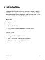
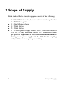
BS500
500ml Bottle Sampling Unit
User Guide
www.mpfiltri.co.uk
200.307-EN
Covers Model Numbers
BS500
SAFETY WARNING
Hydraulic systems contain dangerous fluids at high pressures and
temperatures. Installation, servicing and adjustment is only to be
performed by qualified personnel.
Do not tamper with this device.
Document Revision 1.0
Contents
1
Introduction
5
2
Scope of Supply
6
3
Specification
7
4
Preliminary operations
8
•Precautions
5
Fluid/Assembly Preparation and Analysis
•Flushing and Flushing Fluids
•Procedure
•De-aeration
11
•Operating
with contamination monitoring . . .
6
Information
17
•Warranty •Spare Product / Part Numbers
7
Fault Finding
18
Document Revision 1.0
1 Introduction
The Bottle Sampler is an off-line unit designed to be used with LPA2
and CML2 for accurate contamination monitoring suitable for laboratory applications utilising mineral oil as the operating fluid. Please
contact your local sales office for alternative fluid options.
Benefits
•
Easy to use
•
Large sample volume sampling up to 500ml bottles
•
De-aeration facility
Check that...
•
the operator has read this manual
•
all the accessories are present and correct
•
there is no damage to any of the components
Introduction
5
2 Scope of Supply
Each standard Bottle Sampler supplied consists of the following:•
•
•
•
•
•
6
1 x 500ml Bottle Sampler, base unit and removable top chamber
1 x BS500 User guide
1 x 0.6m Minimess hose
3 x 200ml bottles
2 x 500ml bottles
1 x 12V DC power supply (Mascot 9887), with rated output of
12V DC, 3.33amp maximum current. DC connector is centre
pin positive. Important: do not use the contamination monitoring product power supply with the 500ml bottle sampling
unit, as it has an inadequate power rating
Scope of Supply
3 Specification
Power supply
12V DC power supply (Mascot 9887), with rated output of 12V DC, 3.33amp maximum current.
Indicator
Visiwink pressure indicator
Fluid compatibility
Mineral oil compatible - please contact sales team for
queries about other fluids
Hoses
600mm minimess hose
Viscosity
400 cSt maximum fluid viscosity
Ambient temperature
-10°C Min to 80°C Max
Working temperature
0°C Min to 40°C Max
Dimensions
340mm(H) x 264mm(W) x 350mm(D)
Weight
7kg
As a policy of continual improvement, MP Filtri UK reserve the right to alter the
specification without prior notice.
Figure 1
Specification
7
4 Preliminary operations
4.1 Precautions
4.1.1 Internal Cleaning
Take care when cleaning the transparent cylinder, areas around the seals and surrounding metal work.
clean the Bottle Sampler with Acetone or similar solvents that are not
compatible with the seals. The recommended cleaning fluid for internal flushing
is listed on the website: www.mpfiltri.co.uk. Refer to key drawing on page 7.
DO NOT
4.1.2 Pressurisation and Opening
Always make sure that the top chamber is fully engaged before switching on the
product.
Always make sure to vent the product of pressure prior to opening or re-starting
the pump (check visiwink).
Warning: Turning on the pump with the unit pressurised can reduce the performance of the product and/or cause irreparable damage.
4.1.3 Bottle Cleanliness and Verification
To reduce the risk of your sample container affecting the contamination reading
of your fluid sample, where possible try to use bottles which have been cleaned
and verified to the relevant ISO standards, these include but are not limited to
DIN ISO 3722 - Hydraulic Fluid Power - Fluid Sample Containers - Qualifying
& Controlling Cleaning Methods
8
Preliminary operations
DIN ISO 5884 - Fluid systems and components - Methods for system sampling
and measuring the solid particle contamination of hydraulic fluids
US FED STD 209E Cleanroom Standards - Class 100,000 minimum
ISO 14644-1 Cleanroom Standards - ISO 8 minimum
How to clean and re-use your own bottles
For definitive guidance on the cleaning and verification of glassware refer to
ISO3722 and ISO5884.
Below are some steps based on the above standards. For use with Hydrocarbon/Synthetic/Ester Fluid sampling
1. Fill the container with 50ml acetone, replace the cap, shake vigorously and
drain to a waste container.
2. Fill to 50% of the container volume with 0.4μm filtered Iso-propyl alcohol.
Replace cap, shake vigorously and drain to a waste connector.
3. Fill to 50% of the container volume with 0.4μm filtered Petroleum Ether. Replace cap, shake vigorously and drain to a waste connector.
4. Loosely replace the cap and do not remove until you are ready to take your
next sample. (This allows any trace amounts of Petroleum Ether to evaporate
from the bottle, and reduces the risk of any air-borne particles entering the
container.)
5. Once complete, the fluid sample should be disposed of correctly and responsibly in line with local and international regulations.
For use with Water Based/Off-shore Fluid sampling
1. Fill the container with 50ml Iso-propyl alcohol, replace the cap, shake vigorously and drain to a waste container.
2. Fill to 50% of the container volume with 0.4μm filtered De-ionised water.
Replace cap, shake vigorously and drain to a waste connector.
Preliminary operations
9
3. Fill to 50% of the container volume with 0.4μm filtered De-ionised water.
Replace cap, shake vigorously and drain to a waste connector.
4. Loosely replace the cap and do not remove until you are ready to take your
next sample. (This reduces the risk of any air-borne particles entering the
container.)
5. Once complete, the fluid sample should be disposed of correctly and responsibly in line with local and international regulations.
4.1.4 Fluid Sampling / Hand Pump
We always recommend using our hand pump, clean bottle and hose method which
limits ingress of contamination. Using the hand pump means that the sample
hose can be cleaned or replaced between samples, and the bottle always remains
isolated from the surrounding environment.
Hand pump and hose are available as spares via MP Filtri UK. Please note, only
currently available for 100ml and 200ml size bottles.
10
Preliminary operations
5 Fluid/Assembly Preparation and
Analysis
5.1 Flushing and Flushing Fluids
Prior to performing a test on the contamination monitoring product with a bottle
sampler both units should be flushed in series with a suitable fluid to remove any
traces of previous samples.
For guidance on flushing fluids see the document on the CD supplied with the
contamination monitoring product.
Important! Do NOT use acetone
1.
2.
3.
4.
5.
Bottle sampler
600mm minimess hose
Contamination monitoring product
Waste hose
Waste container
Fluid/Assembly Preparation and Analysis
11
5.2 Procedure
1. Connect minimess hose to the contamination monitoring product.
2. Connect minimess hose (600mm) to the bottle sampling connection.
3. Connect waste fluid hose to contamination monitoring product (waste connector).
4. Insert waste fluid hose into the waste bottle provided.
5. Connect the power supply to bottle sampler, using power adaptor supplied.
6. Switch ON the contamination monitoring product.
7. Select Short Test Sampling option.
8. Enter test details, for more information refer to the contamination monitoring
product user guide.
9. Remove the top chamber by rotating anti clockwise, and then lifting.
10. Place a bottle with minimum 200ml of flushing fluid onto the base unit.
11. Replace the top chamber. The silver spot on the top chamber should be aligned
with the centre of the smallest groove. The top chamber can then be lowered and
the top should be lined up with the silver line between the two lines on the base.
12. Turn the selector handle to Pressure, towards the red disc P.
13. Turn the top valve anti-clockwise to the open position, towards the P.
14. Switch on the BS500.
15. The pressure inside the chamber will slowly increase and the visiwink will turn
red.
16. Once the BS500 stabillises, this takes about 30 seconds, press flush button on the
contamination monitoring product. This is approximately 30 seconds after the
unit is switched on.
12
Fluid/Assembly Preparation and Analysis
17. Press the start button on the contamination monitoring product once about half
the fluid has flushed from the bottle. This will start a short test which will purge
the contamination monitoring product.
18. Once the test is complete press the flush button until all the fluid has flushed
through, if the fluid coming from the waste is clear the contamination monitoring
product and bottle sampler are ready for testing. If the fluid is not clear repeat the
flushing process.
19. Turn off the bottle sampler.
20. Turn the selector handle to Vacuum, towards the yellow disc with V. This will
release the pressure in the chamber.
21. Select Triple or Bottle Test Sampling option on the contamination monitoring
product.
22. Draw off a sample of oil (150 ml. minimum) from the system into the bottle
provided. If this is impractical then use the hand pump, clean bottle and hose
provided to draw off a sample of fluid.
Note: Please ensure that the pump and hose are cleaned with an appropriate
filtered solvent (i.e. Iso-propyl alcohol) prior to the sample being taken.
Sample bottles and associated products are to be cleaned in accordance with
the instructions on page 8.
5.3 De-aeration
It is important when analysing samples for the particles to be evenly distributed
within the sample volume. This is achieved by agitating the sample. This improves the accuracy of readings from the contamination monitoring products as
particles do not settle in the bottom of the bottle due to gravity. This also causes
aeration in the sample which can interfere with the sensitivity of the monitor. The
bottle sampler creates a small vacuum within the chamber. Over a short period of
time, depending on the viscosity, the air bubbles work their way out of the sample.
Fluid/Assembly Preparation and Analysis
13
For full compliance please refer to standard BS11500:2008
23. Agitate sample for minimum 3 minutes, we would always recommend using a
paint shaker, on the highest frequency, to agitate the sample. If a paint shaker is
not available we would recommend 4 to 5 minutes by hand with random direction
movements.
24. Remove the top chamber from the base of the bottle sampler.
25. Place the sample bottle into the bottle sampler.
Note: Do NOT pour oil sample directly into the chamber.
26. Replace the top chamber. The silver spot on the top chamber should be aligned
with the centre of the smallest groove. The top chamber can then be lowered and
the top should be lined up with the silver line between the two lines on the base.
27. Screw top valve clockwise until slight resistance is felt, to close valve.
28. Turn the selector handle to Vacuum, the position nearest the yellow disc marked
V.
29. Switch ON the bottle sampling unit and leave running for several minutes, until all
air bubbles have been removed from the fluid sample. Note: It may be necessary
14
Fluid/Assembly Preparation and Analysis
to vent the chamber on occasion, to stop spill over due to foaming. This is done
by turning the selector handle to Pressure, the position nearest the red disc marked
P.
5.4 Operating with contamination monitoring product
30. Switch OFF the bottle sampler and turn the operating mode selector to the position
nearest the red disc marked P.
Note: The top valve must not be opened BEFORE the operating mode selector
has been changed to the position P. To do so, could allow fluid to reverse flow
back into the sample bottle and contaminate the sample.
31. Screw the top valve on the bottle sampler anticlockwise to open the valve.
32. Switch ON the bottle sampler.
33. The pressure inside the chamber will slowly increase as indicated on the visiwink.
34. Flush the CMP for a minimum of 30 seconds.
Fluid/Assembly Preparation and Analysis
15
35. Start the test.
The Bottle Sampling Test is a three test analysis, as described in the contamination
monitoring product user guide.
36. Upon test completion (after the emptying cycle is completed) switch OFF the
bottle sampler.
37. Turn the operating mode selector slowly to Vacuum (the position nearest the yellow disc marked V). This vents the pressurised chamber to atmosphere. Ensure
sure the visiwink indicator is green before removing the top chamber.
38. Remove the top chamber and remove the sample bottle.
Note: Do not allow oil to drip from the dip tube onto the pressure/vacuum port.
The pressure/vacuum port is the small vertical hole that can be seen in the base
unit after the top chamber has been removed.
39. If you have other samples to analyse, as long as the specification of the fluid is
the same, you can repeat the steps above without carrying out the flushing procedure. If, however the fluid specification is different then it is recommented that
the flushing procedure is followed before performing further testing.
40. Switch OFF the contamination monitoring product.
16
Fluid/Assembly Preparation and Analysis
6 Information
6.1 Warranty
The BS500 is guaranteed for 12 months upon receipt of the unit, subject to it being
used for the purpose intended and operated in accordance with this User Guide.
6.2 Spare Product / Part Numbers
For spare parts please see: www.mpfiltri.co.uk or contact local sales office.
Information
17
7 Fault Finding
FAULT
CHECK
Unexpected results
obtained from sample
Ensure that the minimess hose has been fully connected at both the bottle sampler and the CMP.
Confirm that there is a free flow of fluid to the CMP,
by operating the flush valve and observing fluid passing to waste.
Check that the BS500 is reaching sufficient pressure,
2 to 2.5bar.
Bottle sampler not
reaching required
pressure.
18
Re-grease o-ring in the base of bottle sampler using a
suitable grease, silicone grease is recommended.
Fault Finding
Produced by MP Filtri UK
Revision 1.0
As a policy of continual improvement, MP Filtri UK reserve the right to
alter specifications without prior notice.
Except as permitted by such licence, no part of this publication may be
reproduced, stored in retrieval system or transmitted, in any form or any
means, electronic, mechanical, recording, or otherwise, without prior written permission of MP Filtri UK.