1
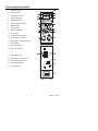
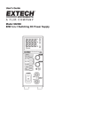
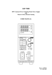
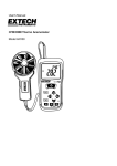
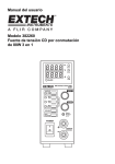
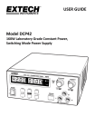
User's Guide
Model 382260
80W 3-in-1 Switching DC Power Supply
Introduction
Congratulations on your purchase of the Extech 80W 3-in-1 Switching DC Power Supply.
The Model 382260 has three output ranges that perform like 3 power supplies in one. It
can be used for many applications including bench testing, field service, hobby and
telecommunication equipment use. This power supply is shipped fully tested and calibrated
and, with proper use, will provide years of reliable service.
Safety
This manual contains important safety and operation instructions for correct use of the
power supply. Read through the manual and pay special attention to the markings and
labels of this unit and equipment to be connected.
Pay special attention to these two types of notices used in this manual
WARNING : Failure to observe this warning may cause injury to persons and
damage to power supply or connected equipment.
CAUTION : Failure to observe this warning may result in damage to equipment and
Improper functioning of the power supply.
WARNING :
1.
2.
3.
4.
5.
6.
Do not use this power supply near water.
Do not operate or touch this power supply with wet hands.
Do not open the casing of the power supply when it is connected to ac
mains.
Refer all servicing to qualified service personnel only.
Before replacing the AC fuse find out and clear up the cause first.
Replace the AC fuse with the same type and rating as the original fuse.
CAUTION :
1.
2.
3.
4.
5.
6.
7.
8.
Use a grounded 3 pin AC source .
This unit is for indoor use only .
Do not operate or place this unit in a humid, dusty, in direct sunlight
location or near any heat source.
Before plugging into local AC mains, check with the rating label at the back
of the unit.
Do not block any ventilation openings of the unit.
This unit must be used within the specified rating, regular excessive
continuous loading may cause damage to the power supply.
The gauge size of input power cable must be at least 0.75mmsq and the
total length of power cable must not exceed 3m.
Input Fuse Recommended: T3AL250V (3A Time-Lag)
2
382260 V1.3 10/08
Power Supply Description
1.
Power On/Off switch
2.
Output terminals
3.
UVL adjustment screw
4.
Current adjustment
5.
Voltage adjustment
6.
Upper Voltage Limit button
7.
Preview button
8.
Range selector
9.
Output On/Off button
10. UVL indicator
11. Constant Voltage indicator
12. Constant Current indicator
13. Overvoltage or Temperature alarm
14. Slave indicator
15. LED Voltage Display
16. LED Current Display
17. Master/Slave switch
18. Master/Slave control terminals
19. Remote Sensing terminals
20. Rear Output terminals
21. AC power socket
3
382260 V1.3 10/08
Stand Alone Operation
1. Set the Master/Slave switch located on the back of the unit to the Master position.
2. Without any load attached, use the POWER button to switch on the power supply and
the LED indicator will light. There should not be any reading on the voltmeter and
ammeter.
3. Press the Output On/Off button and its green LED will light up, the voltmeter will
display the previously set output voltage. Use the voltage control knob to adjust the
voltage to the desired level.
4. Use the Output On/Off button to turn off the output. Note: The output will automatically
shut off when one of the other voltage/current range selection buttons is pushed. This
is to prevent damage to a connected load if the voltage/current values are set too high.
5. Press and Hold the Preview button to display the previously set voltage and current
limiting values. With this button held down, you can set the current limiting value
without connecting to a load or shorting the output terminals. Note: The Output button
must be in the Off position.
Setting the Upper Voltage Limit (UVL) Value
The Upper Voltage Limit Value is an added protection for voltage sensitive loads. When
the output voltage exceeds the set UVL, the output terminal will automatically shut off and
the ALM LED will light. Note: Only one UVL value can be set for all three ranges.
1.
Press the UVL/Voltage and insert a small screwdriver into the UVL adjustment
screw.
2.
Turn clockwise to increase the voltage limit and counter-clockwise to decrease the
UVL value.
Remote Sensing Operation
When the output current is high or the load connection is long, there is a voltage drop
across the connecting cable. This results in a difference between the voltage at the output
terminal and load point. By making an extra connection using the Remote Sensing
Terminal to the load point, the reading at the output terminal and load point is the same.
Caution: Observe correct polarity and never short the Remote Sensing terminal
1.
Connect the load to the power supply.
2.
Connect the load to the Remote Sensing Terminal.
Note: Always disconnect the Remote Sensing terminal connections first.
4
382260 V1.3 10/08
5
382260 V1.3 10/08
Specifications
Display
Dual 4-digit LED
Display Accuracy
±(1% reading + 15 counts)
Voltage Output, DC
0.10 to 16.40V
0.10 to 27.60V
0.10 to 36.80
Current Output, DC
0.100 to 5.100A
0.100 to 3.100A
0.1 to 2.300A
Ripple and Noise
<30mVp-p
Line Regulation
< 4mV/<10mA
Load Regulation
< 20mV/<10mA
Efficiency
>75%
Power Factor
>0.9
Operating %RH
10 to 80% RH
Altitude
2000m
Installation Category
CAT 2
Pollution degree
2
Power
90 to 264VAC (47 to 63Hz)
Supply voltage fluctuation
± 10% of stated operating voltage
Dimensions
13 x 5 x 2" (330 x 127 x 53.5mm) (WxHxD)
Weight
4.2lbs. (1.9 kg)
Warranty
EXTECH INSTRUMENTS CORPORATION warrants this instrument to be free of defects
in parts and workmanship for one year from date of shipment (a six month limited warranty
applies to sensors and cables). If it should become necessary to return the instrument for
service during or beyond the warranty period, contact the Customer Service Department at
(781) 890-7440 ext. 210 for authorization or visit our website www.extech.com for contact
information. A Return Authorization (RA) number must be issued before any product is
returned to Extech. The sender is responsible for shipping charges, freight, insurance and
proper packaging to prevent damage in transit. This warranty does not apply to defects
resulting from action of the user such as misuse, improper wiring, operation outside of
specification, improper maintenance or repair, or unauthorized modification. Extech
specifically disclaims any implied warranties or merchantability or fitness for a specific
purpose and will not be liable for any direct, indirect, incidental or consequential damages.
Extech's total liability is limited to repair or replacement of the product. The warranty set
forth above is inclusive and no other warranty, whether written or oral, is expressed or
implied.
6
382260 V1.3 10/08
Trouble Shooting
PROBLEM
Power supply not
working
INDICATIONS
POSSIBLE CAUSES
Panel display, LED
Indicators not on
A.
B.
No DC output power
Voltage meter zero
indication.
ALM (13) Alarm led on
CC (12) led on
A.
B.
C.
D.
AC power input not
connected
AC input fuse
blown
Output on off button
not on .
UVL (10 )
protection triggered
OTP protection
triggered
Output short circuit
Voltage meter reading
grossly inaccurate
Actual output voltage is
grossly different from
the meter read out
A. Volt meter shows
not the output
voltage.
B. Possible
misalignment in
voltmeter
calibration
Ampere meter reading
grossly inaccurate
In CV mode , the actual
current measured is
grossly different from
the Amp meter reading
All indicators and
display are normal ,
only CC mode has the
problem
Possible misalignment
in calibration .
The activated
(auto- cross over )
c ur re nt limiting value
is different from the
preset cc value
For stand alone unit,
Master & Slave
Switch (17) in wrong
position (Slave). Wrong
setting or connection in
Master & S l a v e o r
s e t u p procedure.
SUGGESTED
SOLUTIONS
A. Check AC power
connection,
B. Contact factory
A. Check output LED
(9) is on or not,
push (9) to on.
B. C h e c k U V L s e t
voltage by pushing
(6), re-set UVL to
applicable limit.
C. Check vent holes at
top and bottom is
clear, ambient
temperature too
high
D. Check and undo
short circuit of
output connection.
A. Check the LED
indicator of UVL on
the top right hand
side of the Volt
meter, if it lights up
then the volt
meter only shows
the set UVL value.
Push (6) to go
back to output
voltage.
B . Contact factory
Contact factory
Check the Master &
Slave switch (17)
correct position. Use
stand alone mode to
check power supply
separately without any
connection to slave
units. Follow the
procedure carefully and
make sure there is only
one Master unit.
Calibration and Repair Services
Extech offers repair and calibration services for the products we sell. Extech also provides
NIST certification for most products. Call the Customer Service Department for information
on calibration services available for this product. Extech recommends that annual
calibrations be performed to verify meter performance and accuracy.
7
382260 V1.3 10/08
Support line (781) 890-7440
Technical Support: Extension 200; E-mail: [email protected]
Repair & Returns: Extension 210; E-mail: [email protected]
Product specifications subject to change without notice
For the latest version of this User’s Guide, Software updates, and other
up-to-the-minute product information, visit our website: www.extech.com
Extech Instruments Corporation, 285 Bear Hill Rd., Waltham, MA 02451
Copyright © 2007 Extech Instruments Corporation (a FLIR company)
All rights reserved including the right of reproduction in whole or in part in any form.
more infor for Extech 382260
Phone: 01235 838 555
Email: [email protected]
Web. www.airconcern.co.uk
Air Concern Ltd, Building 173 Curie Avenue Harvell Didcot, Oxfordshire