1
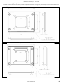
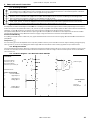
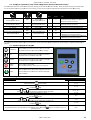
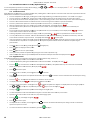
User Guide GV
Optidrive Plus 3 Compact & Optidrive PCE Compact AC Variable Speed Drive & Motor Mount Enclosure 0.75 – 1.5kW (1 – 2HP) Installation and Operating Instructions Optidrive Plus 3GV Compact ‐ User Guide Declaration of Conformity Invertek Drives Ltd hereby states that the Optidrive Plus 3GV Compact and Optidrive PCE product ranges conform to the relevant safety provisions of the Low Voltage Directive 2006/95/EC and the EMC Directive 2004/108/EC, and have been designed and manufactured in accordance with the following harmonised European standards: EN 61800‐5‐1: 2003 Adjustable speed electrical power drive systems. Safety requirements. Electrical, thermal and energy. EN 61800‐3 2nd Ed: 2004 Adjustable speed electrical power drive systems. EMC requirements and specific test methods EN 55011: 2007 Limits and Methods of measurement of radio disturbance characteristics of industrial, scientific and medical (ISM) radio‐frequency equipment (EMC) Specifications for degrees of protection provided by enclosures EN60529 : 1992 Electromagnetic Compatibility (EMC) The Optidrive Plus 3GV Compact is designed to be mounted in close proximity to the driven motor. Within the European Union, equipment into which this product is incorporated must comply with the EMC Directive 2004/108/EC. It is the responsibility of the installer to ensure that the equipment or system into which the product is incorporated complies with the EMC legislation of the country of use. Drive versions are available fitted with an internal EMC filter, designed to reduce the conducted emissions back into the supply via the power cables for compliance with the harmonised European standards. Installation must always be carried out by qualified installation engineers, observing good wiring practice such as power and signal cable segregation and correct screening techniques to minimise emissions. Where the unit is remotely mounted from the motor, screened motor cables must be used with the screen bonded to earth through the largest possible surface area at both ends. When using the internal or optional external filter, compliance with the following EMC Categories, as defined by EN61800‐3:2004 can be achieved: Drive Type / Rating 1 Phase, 230 Volt Input OPC‐1‐12xxx‐1KB1x 3 Phase, 400 Volt Input OPC‐1‐14xxx‐1KA1x Cat C1 Use External Filter OD‐Fx12x EMC Category Cat C2 No additional filtering required Use screened (shielded) motor cable Cat C3 Use External Filter OD‐Fx34x No additional filtering required Use screened (shielded) motor cable Note In a domestic or residential environment, this product may cause radio frequency interference for which the installer may need to take countermeasures. Copyright Invertek Drives Ltd © 2007 All rights reserved. No part of this User Guide may be reproduced or transmitted in any form or by any means, electrical or mechanical including photocopying, recording or by any information storage or retrieval system without permission in writing from the publisher. All Invertek Optidrives carry a 2 year warranty against manufacturing defects from the date of manufacture. The manufacturer accepts no liability for any damages caused during or resulting from transport, receipt of delivery, installation or commissioning. The manufacturer also accepts no liability for damages or consequences resulting from inappropriate, negligent or incorrect installation, incorrect adjustment of the operating parameters of the drive, incorrect matching of the drive to the motor, incorrect installation, unacceptable dust, moisture, corrosive substances, excessive vibration or ambient temperatures outside of the design specification. The local sales partner may offer different terms and conditions at their discretion, and in all cases concerning warranty, the local sales partner should be contacted first. The contents of this User Guide are believed to be correct at the time of printing. In the interest of a commitment to a policy of continuous improvement, the manufacturer reserves the right to change the specification of the product or its performance or the contents of the User Guide without notice. This User Guide is for use with V3.10 Firmware. User Guide Issue 2.00 05/10 Invertek Drives Ltd adopts a policy of continuous improvement and whilst every effort has been made to provide accurate and up to date information, the information contained in this user guide should be used for guidance purposes only and does not form the part of any contract. www.invertek.co.uk 2 Optidrive Plus 3GV Compact ‐ User Guide 1. INTRODUCTION .................................................................................................................................... 4 1.1. Important safety information .......................................................................................................4 2. TECHNICAL DATA .................................................................................................................................. 5 2.1. Environmental ...............................................................................................................................5 2.2. Rating tables .................................................................................................................................5 2.3. Part Number Explanation ..............................................................................................................5 3. MECHANICAL INSTALLATION ................................................................................................................ 6 3.1. General ..........................................................................................................................................6 3.2. Mechanical dimensions and mounting – Compact Drive Module ................................................6 3.3. Enclosure mounting ......................................................................................................................6 3.4. Mechanical Dimensions and Mounting – Optidrive PCE Motor Mount........................................7 3.5. Mounting the Optidrive PCE to a Motor .......................................................................................8 3.6. Motor Mounting Guidelines .........................................................................................................9 4. POWER AND CONTROL CONNECTIONS ............................................................................................... 10 4.1. Grounding the Drive ................................................................................................................... 10 4.2. Wiring Precautions ..................................................................................................................... 10 4.3. Connection Diagram .................................................................................................................. 10 Drive and motor connections .................................................................................................... 11 4.4. 11 4.5. Motor Terminal Box Connections .............................................................................................. 11 4.6. Control terminal connections .................................................................................................... 11 5. OPERATION ........................................................................................................................................ 12 5.1. Optional Optiport Plus Keypad .................................................................................................. 12 5.2. Changing Parameters ................................................................................................................. 12 5.3. Reset All Parameters to Factory Default Settings ...................................................................... 13 5.4. Terminal Control ........................................................................................................................ 13 5.5. Keypad Control ........................................................................................................................... 13 5.6. Motor Autotuning ...................................................................................................................... 14 5.7. Operating in Sensorless Vector Speed Control Mode ................................................................ 14 5.8. Sensorless Vector Torque Control Mode ................................................................................... 14 6. PARAMETERS ...................................................................................................................................... 15 6.1. Parameter Group 1 – Basic Parameters ..................................................................................... 15 6.2. Parameter Group 2 ‐ Extended parameters ............................................................................... 16 6.3. Parameter Group 3 – PID Control .............................................................................................. 18 1. Parameter Group 4 – High Performance Motor Control ........................................................... 18 6.4. Parameter Group 0 – Monitoring Parameters (Read Only) ....................................................... 19 7. ANALOG AND DIGITAL INPUT CONFIGURATIONS ................................................................................ 20 7.1. Terminal mode (P1‐12 =0) ......................................................................................................... 20 Keypad mode (P1‐12 = 1 or 2) .................................................................................................... 21 7.2. 21 7.3. User PI control mode (P1‐12 = 3) ............................................................................................... 21 8. 9. PARAMETER SETTING RECORD............................................................................................................ 22 TROUBLESHOOTING ............................................................................................................................ 24 3 www.invertek.co.uk Optidrive Plus 3GV Compact ‐ User Guide 1. Introduction 1.1. Important safety information Please read the IMPORTANT SAFETY INFORMATION below, and all Warning and Caution information elsewhere. Indicates a potentially hazardous situation which, if not avoided, could result in injury or death. Indicates a potentially hazardous situation which, if not avoided, could result in damage to property. This variable speed drive product (Optidrive) is intended for professional incorporation into complete equipment or systems as part of a fixed installation. If installed incorrectly it may present a safety hazard. The Optidrive uses high voltages and currents, carries a high level of stored electrical energy, and is used to control mechanical plant that may cause injury. Close attention is required to system design and electrical installation to avoid hazards in either normal operation or in the event of equipment malfunction. System design, installation, commissioning and maintenance must be carried out only by personnel who have the necessary training and experience. They must carefully read this safety information and the instructions in this Guide and follow all information regarding transport, storage, installation and use of the Optidrive, including the specified environmental limitations. The level of integrity offered by the Optidrive control functions – for example stop/start, forward/reverse and maximum speed, is not sufficient for use in safety‐critical applications without independent channels of protection. All applications where malfunction could cause injury or loss of life must be subject to a risk assessment and further protection provided where needed. Within the European Union, all machinery in which this product is used must comply with Directive 2006/42/EC, Safety of Machinery. In particular, the machine manufacturer is responsible for providing a main switch and ensuring the electrical equipment complies with EN60204‐1. The driven motor can start at power up if the enable input signal is present. The STOP function does not remove potentially lethal high voltages. ISOLATE the drive and wait 10 minutes before starting any work on it. Electric shock hazard! Disconnect and ISOLATE the Optidrive before attempting any work on it. High voltages are present at the terminals and within the drive for up to 10 minutes after disconnection of the electrical supply. Where supply to the drive is through a plug and socket connector, do not disconnect until 10 minutes have elapsed after turning off the supply. Ensure correct earthing connections. The earth cable must be sufficient to carry the maximum supply fault current which normally will be limited by the fuses or MCB. Suitably rated fuses or MCB should be fitted in the mains supply to the drive. Flammable material should not be placed close to the drive Parameter P1‐01 can be set to operate the motor at up to 30,000 rpm, hence use this parameter with care. If it is desired to operate the drive at any frequency/speed above the rated speed (P1‐09/ P1‐10) of the motor, consult the manufacturers of the motor and the driven machine about suitability for over‐speed operation. Carefully inspect the Optidrive before installation to ensure it is undamaged The Optidrive Plus 3GV Compact has an Ingress Protection rating of IP00 and must be installed in a suitable enclosure. Optidrives are intended for indoor use only. Do not perform any flash test or voltage withstand test on the Optidrive. Any electrical measurements required should be carried out with the Optidrive disconnected. The entry of conductive or flammable foreign bodies should be prevented Relative humidity must be less than 95% (non‐condensing). Ensure that the supply voltage, frequency and no. of phases (1 or 3 phase) correspond to the rating of the Optidrive as delivered. Never connect the mains power supply to the Output terminals U, V, W. Do not install any type of automatic switchgear between the drive and the motor Wherever control cabling is close to power cabling, maintain a minimum separation of 100 mm and arrange crossings at 90 degrees Ensure that all terminals are tightened to the appropriate torque setting www.invertek.co.uk 4 Optidrive Plus 3GV Compact ‐ User Guide 2. Technical data 2.1. Environmental Operational ambient temperature range Storage ambient temperature range Maximum altitude Maximum humidity : ‐10 … 60°C, Frost and condensation free : ‐40 … 60°C : 2000m. Derate above 1000m : 1% / 100m : 95%, non‐condensing 2.2. Rating tables 200‐240V ±10% ‐ 1 Phase Input – 3 Phase Output, Without EMC Filter Model OPC‐1‐12075‐1K01x OPC‐1‐12150‐1K01x kW HP Nominal Input Current 0.75 1.5 1 2 Amps 12.5 14.8 Fuse or MCB (type B) Amps 16 16 Supply Cable Size Nominal Output Current mm2 1.5 1.5 Amps 4.3 7 150% Output Current 60 secs Amps 6.4 10.5 Motor Cable Size 150% Output Current 60 secs Amps 6.4 10.5 Motor Cable Size mm2 1 1.5 Max Motor Cable Length m 10 10 200‐240V ±10% ‐ 1 Phase Input – 3 Phase Output, With EMC Filter Model OPC‐1‐12075‐1KB1x OPC‐1‐12150‐1KB1x kW HP Nominal Input Current 0.75 1.5 1 2 Amps 12.5 14.8 Fuse or MCB (type B) Amps 16 16 Supply Cable Size Nominal Output Current mm2 1.5 1.5 Amps 4.3 7 mm2 1 1.5 Max Motor Cable Length m 10 10 380‐480V ±10% ‐ 3 Phase Input – 3 Phase Output Without EMC Filter Model OPC‐1‐14075‐3K01x OPC‐1‐14150‐3K01x kW HP Nominal Input Current Fuse or MCB (type B) Supply Cable Size Nominal Output Current 0.75 1.5 1 2 Amps 2.9 5.4 Amps 6 6 mm2 1 1 Amps 2.2 4.1 150% Output Current 60 secs Amps 3.3 6.1 Motor Cable Size 150% Output Current 60 secs Amps 3.3 6.1 Motor Cable Size mm2 1 1 Max Motor Cable Length m 10 10 380‐480V ±10% ‐ 3 Phase Input – 3 Phase Output With EMC Filter Model OPC‐1‐14075‐3KA1x OPC‐1‐14150‐3KA1x kW HP Nominal Input Current Fuse or MCB (type B) Supply Cable Size Nominal Output Current 0.75 1.5 1 2 Amps 2.9 5.4 Amps 6 6 mm2 1 1 Amps 2.2 4.1 mm2 1 1 Max Motor Cable Length m 10 10 2.3. Part Number Explanation Product Family Generation Frame Size Input Voltage Rating Power Rating 5 OPC ‐ 1 ‐ 1 2 2 = 200 – 240 Volt + / ‐ 10% 4 = 380 – 480 Volt + / ‐ 10% 075 = 0.75kW 150 = 1.5kW 075 ‐ 1
K
B
1
2
Enclosure
Power Type
Input Phases
2 = IP00 Module Only
N = IP55 Motor Mount
S = IP55 Motor Mount with Pot & Switch
1 = No Brake Transistor
0 = No Internal Filter
A = Internal EMCFilter
B = Internal EMC Filter
K = kW 1 = Single Phase Supply
3 = 3 Phase Supply Brake Transistor
Filter Type
www.invertek.co.uk Optidrive Plus 3GV Compact ‐ User Guide 3. Mechanical Installation 3.1. General Store the Optidrive in its box until required. Storage should be clean and dry and within the temperature range –40°C to +60°C The Optidrive must be installed in a pollution degree 1 or 2 environment 3.2. Mechanical dimensions and mounting – Compact Drive Module Top View Base View 120mm 104.5mm
106mm 91.5mm Mounting Location Holes Four Total, located at each corner, 4.3mm Diameter suitable for M4 screws, 2.5Nm Max.
Motor & Control Terminals End View Power Connection End View 66mm
3.3. Enclosure mounting •
•
•
•
•
•
The Optidrive Plus 3GV Compact is supplied in an IP20 enclosure, designed to be mounted by the user on a thermally conductive material to dissipate the heat generated by the drive. Typically, this can be a motor or steel control panel. The temperature of the heatsink and drive module must be maintained in the range ‐10 to + 65°C The ambient temperature around the drive must not exceed 60°C Typically power losses are approximately 3% of motor absorbed power If the external environment contains contamination particles (e.g. dust), the unit should be suitably protected to ensure no damage can occur. High moisture, salt or chemical content environments should use a suitably sealed (non‐vented) enclosure. www.invertek.co.uk 6 Optidrive Plus 3GV Compact ‐ User Guide 3.4. Mechanical Dimensions and Mounting – Optidrive PCE Motor Mount Top View (Switched version shown) Side View End View 7 www.invertek.co.uk Optidrive Plus 3GV Compact ‐ User Guide 3.5. Mounting the Optidrive PCE to a Motor In order to mount the enclosure onto a motor, a suitable adaptor place should be used. In general, this will require removal of the motor terminal box. A range of adaptor plates are available, as shown below :‐ Adaptor Plate Part Number OPT‐PCEAP‐01 Shallow Adaptor Plate Adaptor Plate Part Number OPT‐PCEAP‐02 Deep Adaptor Plate www.invertek.co.uk 8 Optidrive Plus 3GV Compact ‐ User Guide 3.6. Motor Mounting Guidelines Remove the motor terminal box and mount the adaptor plate to the motor. Assemble the Adaptor Plate to the Motor Assemble the Enclosure to the Adaptor PLate 9 www.invertek.co.uk Optidrive Plu
us 3GV Compactt ‐ User Guide
4. Po
ower and C
Control Connections 4.1. Grou
unding the Drrive oper installation. Invertek Drivves Ltd cannot assume respon
nsibility for the compliance or the This manuaal is intended ass a guide for pro
non‐compliance to any cod
de, national, local or otherwisse, for the proper installation o
of this drive or associated equipment. A hazaard of uipment exists if codes are ign
nored during insstallation. personal injjury and/or equ
oval of main sup
pply. Before wo
orking on the This Optidriive contains higgh voltage capaacitors that takee time to dischaarge after remo
Optidrive, eensure isolation
n of main supplyy from line inpu
uts. Wait ten (1
10) minutes for capacitors to d
discharge to saffe voltage levelss. or loss of life. Failure to observe this preecaution could rresult in severee bodily injury o
Only qualified electrical peersonnel familiaar with the construction and o
operation of this equipment an
nd the hazards involved should install, adju
ust, operate, or service this equ
uipment. Read and understand this manual aand other applicable manuals in their entiretty ould result in se
evere bodily injury or loss of life. before procceeding. Failuree to observe thiis precaution co
Groun
nding Guidelin
nes Each Optidrive should
d be individuallyy connected DIR
RECTLY to the ssite ground buss bar (through the filter if instaalled). Optidrive
e ground conneections should not loop from one Optidrive tto another, or tto, or from any other equipme
ent. Ground loo
op impedance m
must confirm to
o local industriaal safety regulattions. To meet U
UL regulations, UL approved ring crimp terminals should be
e used for all gro
ound wiring con
nnections. The Op
ptidrive Safety G
Ground must bee connected to system ground
d. Ground impe
edance must co
onform to the reequirements off national and lo
ocal industrrial safety regulations and/or eelectrical codess. The integrity of all ground co
onnections should be checked
d periodically. Groun
nd Fault Monittoring If a systtem ground fau
ult monitor is to
o be used, only Type B devicess should be used to avoid nuisance tripping. A
An individual de
evice should bee used per Opttidrive. Safetyy Ground This is tthe safety ground for the Optiidrive that is required by codee. One of these points must bee connected to adjacent building steel (girderr, joist), a floor ground rod, or bus bar. Groun
nding points mu
ust comply with
h national and llocal industrial safety regulatio
ons and/or elecctrical codes. 4.2. Wirin
ng Precautio
ons ections in general: Star Connecct the Optidrivee according to ssection 0, ensurring that motorr terminal box cconnections aree correct. Theree are two conne
and Deelta. It is essentiial to ensure that the motor iss connected in aaccordance with the voltage at which it will b
be operated. Fo
or more informaation, refer to
o section 4.5. 4.3. Conn
nection Diagrram – Non SSwitched Uniits & Modulees Incoming Supply Connecctions For 3 Phase Drives, Connecct L1, L2, L3 For 1 Phase Drives, Connecct L1 / L and L2 / N Motor Connecctions (Fast On Type) Protecttive Earth Control Terminal Strip
p 1 + 24 Volt Com
mmon 2 Digital In
nput 1 3 4 5 6 Digital In
nput 2 Analog In
nput 1 Control Terrminal Strip
Volt Free Relay Output
Analog In
nput 2 0 Volt Com
mmon 7 8 ww
ww.invertek.co
o.uk
10 Optidrive Plu
us 3GV Compactt ‐ User Guide
4.4. Drivee and motor connectionss For 1 phase supply po
ower should be connected to LL1/L, L2/N Screw
w Terminals. For 3 phase supplies p
power should be connected to
o L1, L2, and L3 Screw Terminaals. Phase sequ
uence is not imp
portant. The mo
otor should be cconnection to tthe U, V, and W
W ‘Fast On’ term
minals. 4.5. Moto
or Terminal B
Box Connecttions Most general purposee motors are wo
ound for operattion on dual vo
oltage supplies. This is indicateed on the nameeplate of the mo
otor This op
perational voltage is normally sselected when installing the m
motor by selectiing either STAR
R or DELTA conn
nection. STAR aalways gives the higher of the two voltage ratings. Incomingg Supply Voltage Motor Nameplate Voltagges Connecttion 230 2
230 / 400 Delta 400 4
400 / 690 400 2
230 / 400 Star 4.6. Contrrol terminal connectionss Control Terminal Signal 1 +2
24V User Outpu
ut, 2 D
Digital Input 1 3 D
Digital Input 2 Analog Input 1 or Digital Input 3) (o
Analog Input 2 A
(o
or Digital Input 4) 6 0V
V User gro
ound connected
d terminal 7 7 Relay Common 8 Relay NO Contacct Contact 250Vac, 6A / 30Vdc, 5A 5 11 Deefault Connectio
ons +24V, 10
00mA user conttrol output Positive logic 0V DC “Logic 1”” input voltage range: 8V … 30
“Logic 0”” input voltage range: 0V … 4V
V DC Input : P
Positive logic “Logic 1”” input voltage range: 8V … 30
0V DC “Logic 0”” input voltage range: 0V … 4V
V DC Digital: 8
8 to 30V Analog: 0 to 24V, 0 – 10
0V, ‐10 ‐ +10V, ‐24 ‐ +24V 20mA or 4 to 20
0mA Analog: 0 to 10V, 0 to 2
Digital: 8 to 30V DC 4 Desccription ww
ww.invertek.co
o.uk
Optidrive Plu
us 3GV Compactt ‐ User Guide
4.7. Settin
ngs for typiccal Run / Sto
op switch con
nfigurations (Enclosed Sw
witched Verssion) The tab
ble below show
ws the recommeended parameter settings for u
use with the sw
witched enclosu
ure. Other parameter settings are possible, w
which are nott recommended
d unless using eexternal control wiring, as their functions are
e not designed tto operate with
h the internal sw
witch wiring. Switch Po
osition Run (Preset Speed 1, P
P1‐11) Stop Run (Preset Speed 2, P
P2‐02) Run Reversee Run Reversee Run (Analog Input 2 Speed Reference) Stop Stop Stop Stop P1
1‐12 P2‐01 0 0
0 1, 2 0 0 3
5
0 19
Run Forw
ward (Pot Speed Refference) Run
1, P1‐11) (Preset Speed 1
Run Forw
ward Run Forw
ward Run
(Pot Speed Refference) Ru
un in Speed Con
ntrol Stop Run in PID Control 3 17
Ru
un in Speed Con
ntrol Stop Run in PID Control 3 11
Notes Factory Default Configu
uration Preset SSpeed can be po
ositive or negattive to he direction of rotation define th
positive or negaative to Preset SSpeeds can be p
he direction of rotation define th
Potentio
ometer Speed R
Reference Preset SSpeed 1 (P1‐11) Speed Referen
nce Analog Input required, connect to terminal 5. In Speed
d Control, Pot ccontrols speed
In PID Co
ontrol, pot controls setpoint In Speed
d Control, P1‐11
1 sets the Preseet Speed In PID Co
ontrol, pot controls setpoint 5. Operation O
The Op
ptidrive should be configured p
prior to first operation via the optionally avaiilable Optiport Plus remote keeypad, or Optiw
wand PDA Pockeet PC software. 5.1. Optio
onal Optiporrt Plus Keypa
ad NAVIGATE Used to dissplay real‐time information, to
o access and exxit parameter edit mode and
d to store param
meter changes
UP Used to inccrease speed in
n real‐time mod
de or to increase parameter values in param
meter edit mod
de DOWN Used to deecrease speed in
n real‐time mod
de or to decreaase parameter values in param
meter edit mod
de RESET / STOP Used to resset a tripped drrive. When in Keeypad mode is used to Stop a running drive. START When in keeypad mode, ussed to Start a sttopped drive orr to reverse thee direction of ro
otation if bi‐directional keypad
d mode is en
nabled Chan
nging Parameters Procedu
ure Power o
on Drive Display sshows... Stop
Press and hold the Presss the The P1-02
Keyy an
nd can be used to select the desired parameter S
Select the requ
ired parameterr, e.g. P1‐02 Press tthe Use
P1-01
for >>2 seconds th
he 10.0
P1-02
keyy The paarameter value is now adjusteed and automattically stored. P
Press the operating mode P1-02
0.0
butto
on and kkeys to adjust tthe value, e.g. sset to 10 Presss the P1-03
P
etc...
key for >2 seco
onds to return to Stop
ww
ww.invertek.co
o.uk
12 Optidrive Plu
us 3GV Compactt ‐ User Guide
5.3. Resett All Parameeters to Facto
ory Default SSettings To reseet all Optidrive parameters to factory default settings, presss
button to acknowledgge and reset thee Optidrive. , for >2s. The display sh
hows ìP-dEFî. Press the and
d 5.4. Term
minal Controll delivered, the O
Optidrive is in the factory defaault state, mean
ning that it is se
et to operate in terminal contrrol mode and all parameters h
have the When d
defaultt values as indiccated in section
n 6 Parameters.. •
Connect thee Optidrive to th
he supply, ensu
uring the correcct voltage and ffusing / circuit b
breaker protecttion – see sectio
on 2.2 on page 5. •
Connect thee motor to the O
Optidrive, ensu
uring the correcct star/delta con
nnection for thee voltage ratingg ‐ see section 0
0 on page 11. •
Enter the motor data from motor namepllate; P1‐07 = motor rated voltage, P1‐08 = motor rated currrent, P1‐09 = motor rated freq
quency. •
Connect a co
ontrol switch between the con
ntrol terminals 1 and 2 ensuring that the con
ntact is open (drive disabled). •
Connect a potentiometer (1kΩ min to 10 kΩ max) betweeen terminals 5 and 7, and thee wiper to terminal 6. •
•
With the po
otentiometer seet to zero, switcch on the supplyy to the Optidrive. The displayy will show Sto
oP. Close the co
ontrol switch, teerminals 1‐2. Th
he Optidrive is now ‘enabled’ and the outputt frequency/speeed are controlled by the potentiometer. •
On first enable from factorry default param
meters, the Opttidrive will carry out an Autotu
une, and the display shows Au
uto-t. Leave the control switch closed an allow this to com
mplete. •
•
Following co
ompletion of th
he Autotune, the display show
ws zero speed in
n Hz (H 0 0) with the poten
ntiometer turne
ed to minimum
m. Turn the pottentiometer to maximum. Thee motor will acccelerate to 50H
Hz, (60Hz for USSA drives), the d
default value off P1‐01, under tthe •
control of th
he acceleration ramp time P1‐‐03. The displayy shows 50Hz (H 50 0) at max speed. If the potentiometer is turn
ned to minimum
m, the motor w
will decelerate tto 0Hz, the defaault minimum sspeed set in P1‐‐02, under the ccontrol of the deceleration ramp P
P1‐04. The outp
put speed can b
be adjusted anywhere between
n minimum and
d maximum spe
eed using the potentiometer. •
To display m
motor current (A
Amps), briefly p
press the •
Press •
•
Press aagain to return to speed displaay. To stop the motor, disable the Optidrive b
by opening the control switch (terminals 1‐2)). •
((Navigate) key. aagain to displayy the motor pow
wer. If the enablee/disable switch is opened thee Optidrive will decelerate to sstop at which tiime the displayy will show Sto
oP. 5.5. Keyp
pad Control To allow
w the Optidrivee to be controlled from the keypad in a forwaard direction on
nly, set P1‐12 =1: •
Connect thee supply and mo
otor as for term
minal control ab
bove. •
Enable the O
Optidrive by clo
osing the switch
h between conttrol terminals 1
1 & 2. The displaay will show St
toP. •
Press the key. If this iis the first enab
ble from factoryy default param
meters, the Optiidrive will carryy out an Autotune as described
d he Autotune, th
he display show
ws H
above. On completion of th
0 0. •
Press •
The Optidrivve will run forw
ward, increasingg speed until •
Press in P1‐04 •
Press the •
The display will finally show
w StoP at whiich point the Op
ptidrive is disab
bled •
press the To preset a target speed prrior to enable, p
the tto increase speed. is released.
to decrease speed. The Optidrive will decreaase speed until is releaseed. The rate of deceleration iss limited by the setting ptidrive will deccelerate to restt at the rate set in P1‐04. key. The Op
& key whilst the Optidrive is sto
opped. The disp
play will show the target speed
d, use key to return the disp
play to StoP. keys to ad
djust as requireed then press th
he •
Pressing thee •
•
To allow thee Optidrive to b
be controlled fro
om the keypad in a forward an
nd reverse direection, set P1‐12
2 =2: Operation iss the same as w
when P1‐12=1 fo
or start, stop an
nd changing speed. •
Press the •
Press •
The Optidrivve will run forw
ward, increasingg speed until speed is thee speed set in P1‐01. •
To reverse tthe direction off rotation of thee motor, press tthe key will start the Optid
drive acceleratin
ng to the targett speed. 13 key. The diisplay changes tto H
0 0. tto increase speed 03. The maximu
um is released. Acceleration iss limited by thee setting in P1‐0
key aagain. ww
ww.invertek.co
o.uk
Optidrive Plu
us 3GV Compactt ‐ User Guide
5.6. Moto
or Autotunin
ng Optidrive Plus uses a ssophisticated V
Voltage Vector C
Control Method
d as a factory default setting to ensure best p
possible motor operation. Thiss controll method requirres the Optidrivve to carry out an autotune to
o measure certaain motor param
meters prior to operation, to e
ensure this funcction operatees correctly, an
nd reduce the riisk of nuisance tripping. ot drive or spin the motor, the motor shaft m
may still turn. It is not normally necessary to Whilst thee autotune proccedure does no
uncouple the load from tthe motor; how
wever the user sshould ensure tthat no risk arisses from the po
ossible moveme
ent of the moto
or shaft. Autotu
une after Facttory Reset or from Factoryy Set Parameters Followiing a factory reset (See section
n 5.3), the correect data from the motor name
eplate should b
be entered in P1
1‐07 (Motor Rated Voltage), P
P1‐08 (Motorr Rated Currentt) and P1‐09 (M
Motor Rated Frequency). Provid
ding that P1‐08
8 is adjusted fro
om the factory d
default setting, the Optidrive w
will automaatically carry ou
ut an autotune on the motor tthe first time it is enabled. Durring the autotune, the display will show Auto-t. The test procedure may take several minutess to complete depending on th
he motor. Once the autotune iis completed, th
he Optidrive wiill operate as no
ormal, and no further autotu
uning will be req
quired unless th
he motor or driive control mod
de is changed (P
P4‐01). User SSelected Autotune The useer can program
m the Optidrive tto carry out an autotune if req
quired, as follow
ws:‐ Ensure the motor nam
meplate values are correctly en
ntered as descrribed above. ow access to Paarameter Group
ps 2, 3 and 4 Set P1‐14 = 101 to allo
Set P4‐02 = 1 and presss the buttton. The autotune will begin iimmediately when P4‐02 is seet to 1, and no e
external enablee signal is requirred. During the
e autotune proccedure, the motorr shaft may turn
n. It is not norm
mally necessaryy to uncouple th
he load from the motor; howeever the user sh
hould ensure that no risk arisess from the possible movementt of the motor sshaft. 5.7. Operrating in Sensorless Vecttor Speed Control Mode Optidrive Plus can be programmed b
by the user to operate in Senso
orless Vector m
mode, which pro
ovides enhanceed low speed to
orque, optimum
m motor ontrol of the mo
otor torque. In most applicatio
ons, the defaultt Voltage Vecto
or control modee will speed rregulation regardless of load aand accurate co
providee adequate performance, how
wever if Sensorless Vector operation is required, the followin
ng procedure should be follow
wed:‐ Ensure the motor nam
meplate values are correctly en
ntered in P1‐07
7 (Motor Rated Voltage), P1‐08
8 (Motor Rated
d Current) and P
P1‐09 (Motor R
Rated Frequency) Set P1‐14 = 101 to allo
ow access to paarameter group
ps 2, 3 and 4 otor Rated Pow
wer Factor from the motor nam
meplate MUST b
be entered in P
P4‐05. If this datta is not availab
ble, consult the
e motor manufaacturer The Mo
for guid
dance. Set P4‐01 = 0 to selectt Sensorless Vector Speed Con
ntrol Set P4‐02 = 1 to carry out an motor aautotune Parameeters P4‐03 and
d P4‐04 have a ssignificant effecct on the behavviour of the mo
otor when operating in vector mode, see secttion 1.1 for furtther details,, or the Optidrivve Plus Advanced User Guide. The autotune will begin iimmediately when P4‐02 is seet to 1, and no e
external enablee signal is requirred. During the
e autotune proccedure, the motorr shaft may turn
n. It is not norm
mally necessaryy to uncouple th
he load from the motor; howeever the user sh
hould ensure that no risk arisess from the possible movementt of the motor sshaft. 5.8. Senso
orless Vector Torque Con
ntrol Mode
For app
plications which
h require the Optidrive to conttrol motor torq
que as opposed to motor speeed, the Optidrive Plus can be p
programmed to operatee in Torque Con
ntrol mode. Wh
hen operating tthis way, the drrive internal ram
mp times (P1‐03
3 and P1‐04) arre disabled exce
ept during startting and stoppin
ng. Please referr to the Optidrivve Plus Advanceed User Guide ffor further info
ormation on thiss. ww
ww.invertek.co
o.uk
14 Optidrive Plus 3GV Compact ‐ User Guide 6. Parameters 6.1. Parameter Group 1 – Basic Parameters Par. Units Hz Rpm Hz Rpm Default 0.0 to 3000.0 seconds 5.0 Deceleration ramp time 0.0 to 3000.0 seconds 5.0 P1‐05 Stop mode select 0 : Ramp stop (brown‐out ride‐through) 1 : Coast to stop 2 : Ramp to stop (fast stop) ‐ 0 P1‐06 Energy Optimiser 0: Disabled 1: Enabled ‐ 0 P1‐07 Motor rated voltage 0, 20 to 250 0, 20 to 500 Volts 230 400 Motor rated current Motor rated frequency 25% ‐100% of drive rated current Amps Drive rating Hz 50 P1‐01 P1‐02 P1‐03 P1‐04 P1‐08 P1‐09 Description Maximum Frequency / Speed Minimum Frequency / Speed Acceleration ramp time Range P1‐02 to 5*P‐09 (max 500Hz) 0.0 to P1‐01 25Hz to 500Hz 50.0 0.0Hz Explanation Maximum speed limit – Hz or rpm. If P1‐10 >0, the value entered is in Rpm Minimum speed limit – Hz or rpm. If P1‐10 >0, the value entered is in Rpm Acceleration ramp time from 0 to base speed (P1‐
09) in seconds Deceleration ramp time from base speed (P1‐09) to standstill in seconds. When set to zero, fastest possible ramp time without trip is activated 0 : If the mains supply is lost, the Optidrive will try to continue running by reducing the speed of the load using the load as a generator. 1 : When the enable signal is removed from the drive, the motor will coast (freewheel) to stop 2 : If the mains supply is lost, the Optidrive will ramp to stop using the P2‐25 decel ramp time When enabled, automatically reduces applied motor voltage on light load. Minimum value is 50% of nominal Rated (nameplate) voltage of the motor (Volts). Value limited to 250V for low voltage drives. Setting to zero disables voltage compensation Rated (nameplate) current of the motor Rated (nameplate) frequency of the motor When non‐zero, all speed related parameters are displayed in rpm Sets the speed the Optidrive runs at when Preset P1‐11 Preset Speed 1 ‐P1‐01 to P1‐01 Hz 50.0 Speed 1 is selected Primary Control Mode of the Optidrive. 0 : Terminal control Terminal / Keypad / 0.Terminal control 1 : Uni‐directional keypad control. Keypad START 1. Keypad control – fwd only PID ‐ 0 button does not reverse direction. P1‐12 Drive Control Mode 2. Keypad control − fwd and rev
2 : Bi‐directional keypad control. Keypad START Selection 3. PID Control button toggles between forward and reverse. 3 : PID control with external feedback signal Previous 4 trips stored in order of occurrence, with the most recent first. P1‐13 Trip log Last four trips stored ‐ Read only Press UP or DOWN to step through all four. The most recent trip is always displayed first. UV trip is only stored once. Set to “101” (default) for extended menu access. Extended menu P1‐14 Code 0 to 9 999 ‐ 0 Change code in P2‐37 to prevent unauthorised access access to the Extended Parameter Set Following a factory reset, or when installing a Optidrive for the first time, only Group 1 Parameter access is available. To allow access to Parameters Groups 0, 2, 3 and 4, Parameters P1‐14 and P2‐37 must contain the same value. The factory set value for P2‐37 = 101 P1‐10 15 Motor rated speed 0 to 30 000 rpm Rpm www.invertek.co.uk 0 Optidrive Plus 3GV Compact ‐ User Guide 6.2. Parameter Group 2 ‐ Extended parameters Par. Description Range Units Default P2‐01 Digital input function select 0 to 22 ‐ 0 P2‐02 P2‐03 P2‐04 P2‐05 P2‐06 P2‐07 P2‐08 Preset Speed 2 Preset Speed 3 Preset Speed 4 Preset Speed 5 Preset Speed 6 Preset speed 7 Preset speed 8 ‐P1‐01 to P1‐01 ‐P1‐01 to P1‐01 ‐P1‐01 to P1‐01 ‐P1‐01 to P1‐01 ‐P1‐01 to P1‐01 ‐P1‐01 to P1‐01 ‐P1‐01 to P1‐01 Hz Hz Hz Hz Hz Hz Hz 0.0 0.0 0.0 0.0 0.0 0.0 0.0 P2‐09 Skip frequency P1‐02 to P1‐01 Hz 0.0 P2‐10 Skip frequency band 0.0 to P1‐01 Hz 0.0 P2‐11 P2‐12 Reserved Reserved User Relay Output Function Select 0 : Drive enabled 1 : Drive healthy 2 : Motor at target speed 3 : Motor Speed >0 4 : Motor speed >= limit 5 : Motor torque >= limit nd
6 : 2 Analog Input >= limit 1 0.0 to 200.0 % 100.0 0.0 to 200.0 % 100.0 P2‐13 P2‐14h P2‐14L Relay Output Control High Limit Relay Output Control Low Limit P2‐15 Relay Output Mode 0 : Normally Open 1 : Normally Closed ‐ 0 P2‐16 Zero Speed Holding Time 0.0 to 60.0 s 0.2 P2‐17 Start Mode Select Edge-r
Auto-0
Auto-1 to 5 ‐ Auto-0
P2‐18 Reserved ‐ ‐ P2‐19 Keypad Restart Mode 0 : Minimum Speed, Edge‐r 1 : Previous Speed, Edge‐r 2 : Minimum Speed, Auto‐r 3: Previous Speed, Auto‐r ‐ 0 P2‐20 Standby Mode 0.0 : Disabled 0.1 to 60 s 0.0 www.invertek.co.uk Explanation Defines the function of the digital inputs depending on the control mode setting in P‐12. See section 7 Analog and Digital Input Configurations for more information. Sets jog / preset speed 2 Sets jog / preset speed 3 Sets jog / preset speed 4 Sets jog /preset speed 5 Sets jog / preset speed 6 Sets jog / preset speed 7 Sets jog / preset speed 8 Centre point of skip frequency band set up in conjunction with P2‐10 Width of skip frequency band centred on frequency set in P2‐09 Selects the function assigned to the relay output. 0 : Logic 1 when the drive is enabled (Running) 1: Logic 1 When no Fault condition exists on the drive 2 : Logic 1 when the motor speed matches the setpoint speed 3 : Logic 1 when the motor runs above zero speed Options 4 to 6 : the Digital output is enabled using the level set in P2‐14h and P2‐14L With P2‐13 = 4 to 6, the User Relay Output is set to Logic 1 (+24V DC) when the value set in P2‐14h is exceeded, and returns to Logic 0 (0V) when the selected value reduces below the limit set in P2‐12L Inverts the operating status of the User Relay 0 : Logic 1 = Relay Contacts Closed 1 : Logic 1 = Relay Contacts Open The Optidrive must be powered for the contacts to close Determines the time for which the Optidrive output is held at zero speed when stopping, before the drive output is disabled Edge‐r : Following Power on or reset, the Optidrive will not start if Digital Input 1 remains closed. The Input must be closed following a power on or reset to start the drive. Auto‐0 : Following a Power On or Reset, the Optidrive will automatically start if Digital Input 1 is closed. Auto 1 to 5 : Following a Fault, the Optidrive will make up to 5 attempts to restart at 20 second intervals. The drive must be powered down to reset the counter No Function Active when P1‐12 = 1 or 2 0 : Following a stop and restart, the Optidrive will run at minimum speed 1 : Following a stop and restart, the Optidrive will run at the last setpoint speed 2 : As per setting 0, except that the Run command will be determined by the status of Digital Input 1, and the user is not required to press the keypad start button 3 : As per setting 1, except that the Run command will be determined by the status of Digital Input 1, and the user is not required to press the keypad start button When P2‐20 >0, the Optidrive enters standby mode if the minimum speed is maintained for the time period set in P2‐20 16 Par. P2‐21 Description Display Scaling Factor Range Optidrive Plus 3GV Compact ‐ User Guide Units Default Explanation 0.000 to 30.000 ‐ 0.000 ‐ 0 kHz 16 8 0.0 to 30.0 s 0.0 ‐ ‐ 0: Disabled 1 to 63 ‐ 1 nd
P2‐22 Display Scaling Source 0 : 2 Analog Input 1 : Motor Speed 2 : Motor Torque 3 : Motor Current P2‐24 Effective Switching Frequency 4 to 16 / 24 / 32 Drive Power Rating Dependent P2‐25 2 Deceleration Ramp time nd
P2‐26 P2‐27 Reserved Drive Communication Address P2‐28 Master / Slave Mode Select 0 : Slave Mode 1 : Master Mode ‐ 0 P2‐29 Digital / Slave speed reference scaling factor 0.0 to 500.0 % 100.0 P2‐30 Analog Input 1 format U 0-24 = 0 ‐ 24V DC U 0-10 = 0 ‐ 10V DC
‐ V 0-24
P2‐31 Analog Input 1 scaling 0.0 to 500.0 % 100.0 P2‐32 Analog Input 1 offset ‐500.0 to 500.0 % 0.0 P2‐33 Analog Input 2 format D 0-24 = Digital U 0-10 = 0 to 10V DC A 4-20 = 4 to 20mA A0-20 = 0 to 20mA ‐ D 0-24
P2‐34 Analog Input 2 scaling 0.0 to 500.0 % 100.0 P2‐35 P2‐36 P2‐37 Digital speed reference scaling control Reserved Extended menu access code 0 : Disabled (No Scaling) 1 : Scaled by P2‐29 2 : Scaled by P2‐29, then bipolar analog input added as an offset 3 : Scaled by P2‐29 and by bipolar analog input ‐ 0 ‐ ‐
0 to 9999 ‐ 101 ‐ 0 Hours ‐ ‐ ‐ Parameter Lock 0 : Unlocked 1 : Locked P2‐39 Hours Run Counter 0 to 99999 P2‐40 Drive Type / Rating N/A 17 Effective power stage switching frequency. Higher frequencies reduce the audible ‘ringing’ noise from the motor, and improve the output current waveform, at the expense of increased drive losses Deceleration 2nd ramp down time Selected Automatically on mains power loss if P1‐05 = 2 Can also be selected by digital inputs, dependent on P2‐01 setting. When set to 0, the Optidrive decelerates as quickly as possible, whilst preventing an overvoltage trip No Function Sets the communication address for the drive when connected on an Optibus Network When in Master Mode, the Optidrive transmits its operational status via the serial data link. All Optidrives on the data link must have unique addresses. Only one Optidrive can be programmed as a Master Scaling factor applied to any speed reference on the serial data link, e.g. in Master / Slave operation, a Slave Optidrive will apply this scaling factor to the transmitted Master speed reference Configures the analog input signal to match the reference connected to terminal 6. Only voltage signals can be directly connected, mA reference signals require an external resistor connection. Scales the analog input by this factor, e.g. if P2‐30 is set for 0 – 10V, and the scaling factor is set to 200.0%, a 5 volt input will result in the drive running at maximum speed (P1‐01) Sets an offset, as a percentage of the full scale range of the input, which is applied to the analog input signal Selects the format for the 2nd analog input Selecting d 0-24 sets the input up as a digital input nd
P2‐38 Disabled if P2‐21 is set to 0. If P2‐21 is set >0, the variable selected in P2‐22 is multiplied by the factor entered in P2‐21, and displayed whilst the Optidrive is running Scales the 2 analog input by the factor set in this parameter Active in Keypad mode (P1‐12 = 1 or 2) and Master / Slave mode only. 1 : Actual Speed = Digital Speed x P2‐29 2: Actual Speed = (Digital Speed x P2‐29) + bipolar analog reference 3 : Actual Speed = Digital Speed x P2‐29 x bipolar analog reference No Function Defines the access code which must be entered in P1‐14 to access parameter groups above Group 1 When locked, all parameter changes are prevented Indicates the number of hours for which the Optidrive has run Read only parameter, showing the Optidrive type and power rating www.invertek.co.uk Optidrive Plus 3GV Compact ‐ User Guide 6.3. Parameter Group 3 – PID Control Par. Description Range Units Default P3‐01 Proportional gain 0.1 to 30.0 ‐ 2.0 P3‐02 Integral time constant 0.0 to 30.0 s 1.0 P3‐03 Differential time constant 0.00 to 1.0 s 0.00 P3‐04 PID operating mode 0 : Direct 1 : Inverse ‐ 0 P3‐05 PID Setpoint / reference select 0 : Digital 1 : Analog ‐ 0 PID digital reference PID controller high limit output PID controller low limit output 0.0 to 100.0 % 0.0 P3‐08 to 100.0 % 100.0 0.0 to P3‐07 % 0.0 P3‐06 P3‐07 P3‐08 P3‐09 User PID output limit / function control 0 : Digital output limits 1 : Analog Upper Limit 2: Analog Lower Limit 3 : PID added to Bipolar analog input reference P3‐10 PID feedback source select 0 : 2 Analog Input 1 : Bipolar analog input Explanation PID Controller Proportional Gain. Higher values provide a greater change in the Optidrive output frequency in response to small changes in the feedback signal. Too high a value can cause instability PID Controller Integral Time. Larger values provide a more damped response for systems where the overall process responds slowly PID Differential Time Constant Direct operation – Motor speed increases with an increase in the feedback signal Inverse Operation – Motor speed decreases with an increase in the feedback signal Selects the source for the PID Reference / Setpoint 0 : P3‐06 is used 1 : Bipolar analog input is used Sets the preset digital PID reference / setpoint Limits the maximum value output from the PID controller Limits the minimum output from the PID controller ‐ 0 0 : PID output range limited by P3‐07 & P3‐08 1 : PID maximum output limited by the signal applied to the bipolar analog input 2: PID minimum output limited by the signal applied to the bipolar analog input 3: PID output is added to the speed reference applied to the bipolar analog input ‐ 0 Selects the source of the PID feedback signal nd
Parameter Group 4 – High Performance Motor Control Par. Description P4‐01 Control Mode P4‐02 Motor parameter autotune P4‐03 Units Default ‐ 2 0 : Disabled 1 : Enabled ‐ 0 Speed controller proportional gain 0 to 4096 ‐ 300 P4‐04 Speed controller integral time 0.050 to 1.000 seconds 0.050 P4‐05 Motor power factor 0.50 to 1.00 ‐ ‐ P4‐06 Torque reference source select 0 : Preset Value 1 : Bipolar analog input 2 : 2nd analog input ‐ 0 When operating in vector mode (P4‐01 = 0 or 1), selects the source of the torque reference 0.0 to 200.0 % 200.0 If P4‐01 = 1 and P4‐06 = 0, sets the preset torque reference If P4‐01 = 0, sets the maximum torque limit 0.0 to 150.0 % 0.0 P4‐07 P4‐08 Maximum torque limit / torque reference Minimum torque limit Range 0 : Vector Speed Control 1 : Vector Torque Control 2 : V/F Speed Control Explanation Selects the motor control method. An autotune must be performed following a change, see section 6.4 When set to 1, the Optidrive immediately carries out a non‐
rotating autotune to measure the motor parameters for optimum control and efficiency Sets the proportional gain value for the speed controller. Higher values provide better output frequency regulation and response. Too high a value may cause instability Set the integral time for the speed controller. Smaller values provide a faster response in reaction to motor load changes, at the risk of introducing instability Motor nameplate power factor, which must be entered for Vector operation (P4‐01 = 0 or 1) Sets a minimum torque limit, see the warning below When operating in V/F mode (P4‐01 = 2), sets a frequency point at which the voltage applied in P4‐10 is applied to the P4‐09 0.0 to P1‐09 Hz 0.0 motor. Care must be taken to avoid over heating and damaging the motor when using this feature V/F characteristic In conjunction with P4‐09, in V/F mode (P4‐01 = 2), sets the P4‐10 adjustment 0 to P1‐07 ‐ 0 voltage applied to the motor at the adjustment frequency set voltage in P4‐09 Incorrect adjustment of parameters in menu group 4 can cause unexpected behaviour of the motor and any connected machinery. It is recommended that these parameters are only adjusted by experienced users V/F characteristic adjustment frequency www.invertek.co.uk 18 Optidrive Plus 3GV Compact ‐ User Guide 6.4. Parameter Group 0 – Monitoring Parameters (Read Only) Par. P0‐01 P0‐02 P0‐03 P0‐04 P0‐05 P0‐06 P0‐07 P0‐08 P0‐09 P0‐10 P0‐11 P0‐12 P0‐13 P0‐14 P0‐15 P0‐16 P0‐17 P0‐18 P0‐19 P0‐20 P0‐21 P0‐22 P0‐23 P0‐24 P0‐25 P0‐26 P0‐27 P0‐28 P0‐29 P0‐30 19 Description Bipolar analog input value 2nd Analog input value Post Ramp Speed Reference Digital speed reference Torque controller reference PID Reference PID Feedback PID error PID P Term PID I term PID D term PID Output Output Torque Magnetising current Rotor Current Field Strength Stator resistance Stator Inductance Rotor resistance DC Bus Voltage Drive Temperature Reserved Reserved Reserved Estimated rotor speed kWh meter MWh meter Software ID – IO Processor Software ID – Motor Control Drive serial number Display range 0 to 100 0 to 100 ‐500 to 500 ‐P1‐01 to P1‐01 0 to 200 0 to 100 0 to 100 0 to 100 0 to 100 0 to 100 0 to 100 0 to 100 0 to 200 Drive dependent Drive dependent 0 to 100 Drive dependent Drive dependent Drive dependent 0 to 1000 0 to 120 ‐ ‐ ‐ Drive dependent 0 to 999.9 0 to 60,000 Drive dependent Drive dependent Drive dependent Units % % % Hz / Rpm % % % % % % % % % A A % Ohms H Ohm Volts ºC ‐ ‐ ‐ Hz / Rpm kWh MWh ‐ ‐ ‐ Explanation 100% = max input voltage 100% = max input voltage 100% = P1‐09 Digital speed reference Torque reference setpoint PID reference / setpoint PID controller feedback value Actual PID error Proportional component Integral component Differential component Output from PID controller 100% = motor rated torque Motor rms magnetising current Rotor rms current Magnetic field strength Phase to phase stator resistance Stator inductance Calculated rotor resistance Internal DC Bus voltage Measured heatsink temperature In vector mode, estimated speed of motor Cumulative energy consumption Cumulative energy consumption Version number & checksum Version number & checksum Unique drive serial number www.invertek.co.uk Optidrive Plus 3GV Compact ‐ User Guide 7. Analog and Digital Input Configurations 7.1. Terminal mode (P1‐12 =0) P2‐01 Digital input 1 (T2) Open: Stop (disable) Closed: Run (enable) Open: Stop (disable) Closed: Run (enable) Open : Bipolar analog speed ref
Closed : Preset speed ref Open: Preset Speed 1
Closed: Preset speed 2 Digital Input 2 Digital Input 3
Open Open
Closed Open
Open Open
Closed Open
Open Closed
Closed Closed
Open Closed
Closed Closed
Open : Forward Closed : Reverse Open : Forward Closed : Reverse 5 Open: Stop (disable) Closed: Run (enable) Open : Forward Closed : Reverse 6 Open: Stop (disable) Closed: Run (enable) Open : Forward Closed : Reverse Open: Stop (disable) Closed: Fwd Run (enable) Open: Stop (disable) Closed: Fwd Run (enable) Open: Stop (disable) Closed: Rev Run (enable) Open: Stop (disable) Closed: Rev Run (enable) 9 Open: Stop (disable) Closed: Forward Run (enable) Open: Stop (disable) Closed: Reverse Run (enable) 10 Open: Stop (disable) Closed: Forward Run (enable) Open: Stop (disable) Closed: Reverse Run (enable) 11 Open: Stop (disable) Closed: Run (enable) Open : Bipolar analog speed ref Closed : Preset speed 1 12 Open: Stop (disable) Closed: Run (enable) Open : Preset Speed 1 Closed : Bipolar analog speed ref Normally Open (NO) Momentarily Close to Run Normally Open (NO) Momentarily Close to Run Fwd Open: Stop (disable) Closed: Run (enable) Open: Stop (disable) Closed: Run (enable) Normally Open (NO) Momentarily Close to Run Fwd Normally Closed (NC)
Momentarily Open to Stop Normally Closed (NC)
Momentarily Open to Stop Open : Forward Closed : Reverse Open : Forward Closed : Reverse Normally Closed (NC)
Momentarily Open to Stop Digital Input 2 Digital Input 4
Open Open
Closed Open
Open Closed
Closed Closed
Open : Bipolar analog speed ref
Closed : Analog input 2 speed ref 0 1 2 3 4 7 8 13 14 15 16 17 18 19 20 21 22 NOTE Open: Stop (disable) Closed: Run (enable) Open: Stop (disable) Closed: Run (enable) Digital input 2 (T3) Open: Stop (disable) Closed: Run (enable) Open: Stop (disable) Closed: Run (enable) Open: Stop (disable) Closed: Run (enable) Open: Stop (disable) Closed: Run (enable) Open: Stop (disable) Closed: Run (enable) Open: Stop (disable) Closed: Run (enable) Analog Input 1 (T4)
(or Digital Input 3) Analog input 2 (T5)
(or Digital Input 4) Open : Preset Speed 1
Bipolar Analog Input Closed : Preset Speed 2 Open : Preset Speed 1 / 2 / 3
Open : Preset Speed 1 / 2
Closed : Preset Speed 4 Closed : Preset Speed 3 Digital Input 4
Speed Setpoint
Open Preset Speed 1
Open
Preset Speed 2
Closed
Preset Speed 3
Closed
Preset Speed 4
Open
Preset Speed 5
Open
Preset Speed 6
Closed
Preset Speed 7
Closed
Preset Speed 8
Open: Bipolar analog ref Bipolar Analog Input Closed: Preset Speed 1 Analog input 2
Bipolar Analog Input (E.g. Torque reference) Digital Input 3
Digital Input 4 Speed Setpoint
Open
Open
Preset Speed 1
Open
Closed
Preset Speed 2
Closed
Open
Preset Speed 3
Closed
Closed
Preset Speed 4
External trip input :
Bipolar Analog Input Open: Trip, Closed: No Trip Open: Bipolar analog speed ref Bipolar Analog Input Closed: Preset Speed 1 Open: Bipolar analog speed ref Bipolar Analog Input Closed: Preset Speed 1 Digital Input 3
Digital Input 4 Preset Speed
Open
Open
Preset Speed 1
Open
Closed
Preset Speed 2
Closed
Open
Preset Speed 3
Closed
Closed
Preset Speed 4
External trip input :
Bipolar Analog Input Open: Trip, Closed: No Trip External trip input :
Bipolar Analog Input Open: Trip, Closed: No Trip External trip input :
Bipolar Analog Input Open: Trip, Closed: No Trip Open: Bipolar analog speed ref Bipolar Analog Input Closed: Preset Speed 1 Normally Open (NO)
Bipolar Analog Input Momentarily Close to Run Rev Open: Decel Ramp 1 (P1‐04) Bipolar Analog Input Closed: Decel Ramp 2 (P2‐25) Open: Preset Speed 1 Open: Decel Ramp 1 (P1‐04) Closed: Preset Speed 2 Closed: Decel Ramp 2 (P2‐25) Open : Preset Speed 1
Normally Open (NO)
Closed : Keypad Mode Momentarily Close to Run Rev Preset Speed Ref
Preset Speed 1
Open : Terminal Mode Preset Speed 2
Closed : Keypad Mode Preset Speed 3
Preset Speed 4
Bipolar Analog Input No Function Bipolar Analog Input No Function Bipolar Analog Input No Function Bipolar Analog Input Analog input 2 Open : Bipolar analog speed ref
Closed : Preset Speed 1 Open : Forward
Closed : Reverse External trip input :
Open: Trip, Closed: No Trip Negative Preset Speeds will be inverted if Run Reverse selected.
The external trip input can be used to connect a motor thermistor by connecting the thermistor between terminals 1 and 4 www.invertek.co.uk 20 Optidrive Plu
us 3GV Compactt ‐ User Guide
7.2. Keyp
pad mode (P1
1‐12 = 1 or 2
2)
P2‐01 Digital inp
put 1 (T2) Analog Input 1 (T4)
(or Digital Inpu
ut 3) Digital in
nput 2 (T3) 0 Open: Stop (d
disable) Closed: Run ((enable) Cllosed : remote UP push‐button No Function 1 Open: Stop (d
disable) Closed: Run ((enable) Cllosed : remote UP push‐button Closed : rem
mote DOWN push‐button Open: Stop (d
disable) Closed: Run ((enable) 3..9, 13
3, Open: Stop (d
disable) 14 & 16
6 Closed: Run ((enable) 2 Cllosed : remote UP push‐button Cllosed : remote UP push‐button Closed : remo
ote DOWN push‐b
button Open : Forw
ward
Closed : Revverse Open : Forw
ward
Closed : Revverse Open: Stop (d
disable) Closed: Run ((enable) Open : Digital speeed ref Cllosed : Bipolar an
nalog speed ref Bipolar Analog Input 11 Open: Stop (d
disable) Closed: Run ((enable) Open : Digital speeed ref Cllosed : Preset speeed 1 Open : Forw
ward Closed : Revverse 12 Open: Stop (d
disable) Closed: Run ((enable) Open : Preset speeed 1 Cllosed : Digital speeed ref Open : Forw
ward Closed : Revverse Open: Stop (d
disable) Closed: Run ((enable) Open: Stop (d
disable) Closed: Run ((enable) Open : Digital speeed ref Cllosed : Preset speeed 1 Open : Digital speeed ref Cllosed : Bipolar an
nalog speed ref Open : Forw
ward
Closed : Revverse 17 18 19 20, 21
1 Open: Stop (d
disable) Closed: Run ((enable) Open : Digital speeed ref Cllosed : Preset speeed ref Open: Stop (d
disable) Closed: Run ((enable) disable) Open: Stop (d
Closed: Run ((enable) Open : Digital speeed ref Cllosed : Analog inp
put 2 ref Open: Stop (d
disable) Closed: Run ((enable) 22 Bipolar Analog Input Digital Inputt 3
Open
Open
Closed
Closed
Open : Forw
ward
Closed : Revverse Open : Forw
ward
Closed : Revverse No Function By default, iff the enable signaal is present the d
drive will not Enable until the signal is pressent set P2‐19 = 2
2 or 3. This then disables the use of the NOTE Digital Input 4 Open
Closed
Open
Closed
External trip input :
Open: Trip, Closed: No Trrip External trip input :
Open: Trip, Closed: No Trrip External trip input :
Open: Trip, Closed: No Trrip Open: Decel R
Ramp 1 (P1‐04) Closed: Decel Ramp 2 (P2‐25)
Open : Digitall / Analog ref
Closed : Prese
et speed 1 Preset reference
P
Preset Speed 1
P
Preset Speed 2
P
Preset Speed 3
P
Preset Speed 4
P
Analog input 2 Open : Digitall speed ref
Closed : Prese
et speed 1 External trip input :
Open: Trip, Closed: No Trrip Open : Forw
ward Closed : Revverse No Function External trip input :
Open: Trip, Closed: No Trrip Open: Digital speed ref
et speed 1 Closed: Prese
Closed : remo
ote DOWN push‐b
button 10 15 Anallog input 2 (T4)
(or D
Digital Input 4) button is presssed. To automatically enable the d
drive when the enable & buttons In keypad mo
ode, the speed caan be adjusted ussing the & keys on th
he built in keypad
d, or a remote mo
ounted Optiport Plus keypad, in addition to p
pushbuttons conn
nected to the digital inputs The reverse iinput only functio
ons under the folllowing condition
ns
P1‐12 == 1, P2‐19 = 2 or 3. P2‐35 must no
ot be 2 or 3 P1‐12 == 2. P 2‐35 must not be 2 or 3 The external trip input can bee used to connectt a motor thermisstor by connectin
ng the thermistorr between termin
nals 1 and 4 7.3. User PI control m
mode (P1‐12 = 3) P2‐01 Digital inp
put 1 (T2) 0..10, O
Open: Stop (disab
ble) 13..16
C
Closed: Run (ena
ble) , 18 Analog Inpu
ut 1 (T4)
(or Digital IInput 3) Digittal input 2 (T3) No Function Bipolarr Analog Input 11 Open: Stop (disab
O
ble) ble) C
Closed: Run (ena
Open : PID conttrol Closed : Preset speed 1 Bipolarr Analog Input 12 Open: Stop (disab
O
ble) C
Closed: Run (ena
ble) Open : Preset sspeed 1 Closed : PID control Bipolarr Analog Input Open: Stop (disab
O
ble) C
Closed: Run (ena
ble) O
Open: Stop (disab
ble) 19 C
Closed: Run (ena
ble) O
Open: Stop (disab
ble) 20, 21 C
Closed: Run (ena
ble) 17 22 NOTE 21 Open : PID Con
ntrol Closed : Bipolarr analog ref Open : PID Con
ntrol Closed : Analogg input 2 ref No Function An
nalog input 2 (T4
4)
(o
or Digital Input 4) Analog input 2 External trip input :
Open: Trip, Closed: No Trip External trip input :
Open: Trip, Closed: No Trip Bipolarr Analog Input Analog inpu
ut 2 Bipolarr Analog Input Analog inpu
ut 2 Bipolarr Analog Input Analog inpu
ut 2 External trip input :
Open: Trip, Closed: No Trip When P3‐05 = 1, Bipolar analogg input controls PID setpoint. The ffeedback must th
hen be connected
d to Analog inputt 2 and P3‐10 must be set to 0 (Deefault setting) The external trrip input only functions when the feedback source is the Bipolar analog input (P3‐10
0 = 1) Open: Stop (disab
O
ble) C
Closed: Run (ena
ble) No Function Bipolarr Analog Input ww
ww.invertek.co
o.uk
Optidrive Plus 3GV Compact ‐ User Guide 8. Parameter Setting Record Parameter P1‐01 P1‐02 P1‐03 P1‐04 P1‐05 P1‐06 P1‐07 P1‐08 P1‐09 P1‐10 P1‐11 P1‐12 P1‐13 P1‐14 P2‐01 P2‐02 P2‐03 P2‐04 P2‐05 P2‐06 P2‐07 P2‐08 P2‐09 P2‐10 P2‐11 P2‐12 P2‐13 P2‐14h P2‐14L P2‐15 P2‐16 P2‐17 P2‐18 P2‐19 P2‐20 P2‐21 P2‐22 P2‐24 P2‐25 P2‐26 P2‐27 P2‐28 P2‐29 P2‐30 P2‐31 P2‐32 P2‐33 P2‐34 P2‐35 P2‐36 P2‐37 P2‐38 P2‐39 P2‐40 Description Maximum Frequency / Speed Minimum Frequency / Speed Acceleration ramp time Deceleration ramp time Stop mode select Energy Optimiser Motor rated voltage Motor rated current Motor rated frequency Motor rated speed Preset Speed 1 Terminal / Keypad / PID Drive Control Mode Selection Trip log Extended menu access Digital input function select Preset Speed 2 Preset Speed 3 Preset Speed 4 Preset Speed 5 Preset Speed 6 Preset speed 7 Preset speed 8 Skip frequency Skip frequency band Reserved Reserved User Relay Output Function Select Relay Output Control High Limit Relay Output Control Low Limit Relay Output Mode Zero Speed Holding Time Start Mode Select Reserved Keypad Restart Mode Standby Mode Display Scaling Factor Display Scaling Source Effective Switching Frequency 2nd Deceleration Ramp time Communication Baud Rate Drive Communication Address Master / Slave Mode Select Digital / Slave speed reference scaling factor Analog Input 1 format Analog Input 1 scaling Analog Input 1 offset Analog Input 2 format Analog Input 2 scaling Digital speed reference scaling control Reserved Extended menu access code Parameter Lock Hours Run Counter Drive Type / Rating Value www.invertek.co.uk 22 P3‐01 P3‐02 P3‐03 P3‐04 P3‐05 P3‐06 P3‐07 P3‐08 P3‐09 P3‐10 P4‐01 P4‐02 P4‐03 P4‐04 P4‐05 P4‐06 P4‐07 P4‐08 P4‐09 P4‐10 23 Optidrive Plus 3GV Compact ‐ User Guide Proportional gain Integral time constant Differential time constant PID operating mode PID Setpoint / reference select PID digital reference PID controller high limit output PID controller low limit output User PID output limit / function control PID feedback source select Control Mode Motor parameter autotune Speed controller proportional gain Speed controller integral time Motor power factor Torque reference source select Maximum torque limit / torque reference Minimum torque limit V/F characteristic adjustment frequency V/F characteristic adjustment voltage www.invertek.co.uk Optidrive Plus 3GV Compact ‐ User Guide 9. Troubleshooting Fault Code P-def
O-I
hO-I
PS-trp
Description Factory Default parameters have been loaded Instantaneous over current on drive output. Excess load on the motor. Over temperature on the drive heatsink I. t-trP
Drive has tripped on overload after delivering >100% of value in P1‐08 for a period of time. OI-b
Brake channel over current O.Uo1t
U.Uo1t
Over voltage on DC bus Under voltage on DC bus O-t
U-t
Heatsink over temperature Under temperature th-Flt
4-20 F
Faulty thermistor on heatsink. External trip (on digital Input 3) 4‐20mA Input Signal Loss data-F
Internal memory fault. At-F01
Autotune Failed At-F02
At-f03
At-F04
At-F05
Spin-F
Spin Start Failure E-triP
Corrective Action Press STOP key, Optidrive is ready to configure for particular application If the fault occurs immediately when enabling the Optidrive, disconnect the motor cable from the output terminals of the Optidrive and restart the drive. If the fault re‐occurs with no motor connected, contact your local Invertek Sales Partner. If the Optidrive runs correctly with no motor connected, check the motor, motor cable and any connections or junction boxes for phase – phase and phase – earth short circuits. Wherever possible, motors and connection cables should be checked with a high voltage insulation tester (Megga) prior to connection to the Optidrive. Ensure that no switching devices, such as contactors or local isolators are switching during operation of the Optidrive. Check the motor cable length does not exceed the specified maximum Ensure the motor nameplate parameters are correctly entered, P1‐07, P1‐08, P1‐09. If operating in Vector mode (P4‐01 – 0 or 1), also check the motor power factor in P4‐05. Ensure an autotune has been successfully completed for the connected motor. Check the load mechanically for a jam or stalled condition, or shock loads. Increase the ramp up time in P1‐03. If operating in Vector mode (P4‐01 – 0 or 1), reduce the speed loop gain in P4‐03 Check to see when the decimal points are flashing (drive in overload) and either increase acceleration rate or reduce the load. Check motor cable length is within spec. Ensure the motor nameplate parameters are correctly entered, P1‐07, P1‐08, and P1‐09. If operating in Vector mode (P4‐01 – 0 or 1), also check the motor power factor in P4‐05. Ensure an autotune has been successfully completed for the connected motor. Check the load mechanically to ensure it is free, and no jams, blockages or other mechanical faults exist Over current in the brake resistor circuit. Check the cabling to the brake resistor. Check the brake resistor value. Ensure minimum resistance values form the rating tables are observed. Supply problem, or increase decel ramp time P‐04. This occurs routinely when power is switched off. If it occurs during running, check power supply voltage. Check drive ambient temp. Additional space or cooling required. Trip occurs when ambient temperature is less than ‐10°C. Temperature must be raised over ‐
10°C in order to start the Optidrive. Refer to your IDL Authorised Distributor. E‐trip requested on digital input 3. Normally closed contact has opened for some reason. If motor thermistor is connected check if the motor is too hot. The level of the 4‐20mA signal applied to analog input 2 (Terminal 4) has dropped below the minimum threshold of 3mA. Check for wiring or signal transducer faults Parameters not saved, defaults reloaded. Try again. If problem recurs, refer to your local Invertek Sales Partner. Measured motor stator resistance varies between phases. Ensure the motor is correctly connected and free from faults. Check the windings for correct resistance and balance. Measured motor stator resistance is too large. Ensure the motor is correctly connected and free from faults. Check that the power rating corresponds to the power rating of the connected Optidrive. Measured motor inductance is too low. Ensure the motor is correctly connected and free from faults. Measured motor inductance is too large. Ensure the motor is correctly connected and free from faults. Check that the power rating corresponds to the power rating of the connected Optidrive. Measured motor parameters are not convergent. Ensure the motor is correctly connected and free from faults. Check that the power rating corresponds to the power rating of the connected Optidrive. Spin start function (P2‐18=1) failed to detect motor speed Check motor and connections. Ensure motor speed is less than maximum speed (P1‐01). Make sure motor base frequency (P1‐09) is <100Hz www.invertek.co.uk 24