1
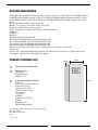
WORCESTER GREENSTORE
6kW, 7kW, 9kW & 11kW System
HEAT PUMP
GB/IE
USER MANUAL
Table of Contents
Table of Contents
BUILDING REGULATIONS ..................................................................................................................................3
Important information ....................................................................................... 4
Technical support ...................................................................................................................................................4
How the heat pump works ................................................................................. 5
Technology in and around the heat pump ................................................................................................................5
Component parts of the heat pump .................................................................... 7
Greenstore System ...................................................................................................................................................7
Rego 637W Control unit .................................................................................... 8
The control unit’s two methods to control the heat pump..........................................................................................9
Control panel .................................................................................................. 10
Controls and status indicators ..............................................................................................................................10
Menu dial .............................................................................................................................................................11
How to use the control panel .................................................................................................................................11
Basic functions (Customer level 1) ................................................................... 11
Menu outline for Basic functions (Customer level 1) .............................................................................................12
Select scrolling information on the menu display ...................................................................................................12
Set the heating ......................................................................................................................................................13
Set the required room temperature ........................................................................................................................16
Set the heat pump for extra hot water ....................................................................................................................16
Heating and hot water settings ..............................................................................................................................17
Read the temperatures on the heat pump ...............................................................................................................17
Extra functions (Customer level 2) ................................................................... 19
Menu outline for Extra functions (Customer level 2) .............................................................................................19
Temperature settings .............................................................................................................................................20
Set extra heat curve with mixing valve ..................................................................................................................21
Hot water settings..................................................................................................................................................22
Timer control ........................................................................................................................................................22
Reading operating times on the heat pump and electric heater ..............................................................................23
Set the time and date ............................................................................................................................................24
Alarms given by the heat pump .............................................................................................................................25
Return to the heat pump’s factory settings ..............................................................................................................25
2
BUILDING REGULATIONS
This appliance must be installed and serviced only by a competent person in accordance with the current: IEE Regulations,
Building Regulation, Building Standards (Scotland) (Consolidation), Building Regulations (Northern Ireland), local water
by-laws, Health & Safety Document 63S (The Electricity at Work Regulations 1989), IS 813 (Eire) and other local requirements.
The relevant Standards should be followed, including:
BS7074:1 : Code of practice for domestic and hot water supply
EN:12828 : Central heating for domestic premises
BS7593 : Treatment of water in domestic hot water central heating systems
BS EN 14511
BS EN 814
BS EN 378
The Health and Safety at Work Act 1974
The Management of Health and Safety at Work Regulations 1999
The Construction (Health, Safety and Welfare) Regulations 1996
The Construction (Design and Management) Regulations 1994
The Lifting Operations and Lifting Equipment Regulations 1998
Where no specific instruction is given, reference should be made to the relevant codes of Practice.
Potable water:
All seals, joints, compounds (including flux and solder) and components used as part of the secondary domestic water
system must be approved for use with potable water supplies.
PRODUCT CONTENTS LIST
600mm
600mm
Greenstore System Heat Pump.
Literature pack:
User manual
Installation manual
Guarantee card
Components included in deliver y:
Rubber feet
Outdoor sensor T2 (GT2) with cable
Room sensor T5(GT5)
Return sensor T1 (GT1)
4 bar Pressure Relief Valve
Valve with filter
Circlip pliers
Drain plug
Cylinder sensor T3 (GT3)
Ball valve
Expansion vessel
Filling link with insulation
1520mm
User manual for the Worcester Greenstore System heat pumps
Worcester, 12.02.07
Part number: 8 716 112 859
Issue: c
Copyright © 2006.
3
Important information
Your new Greenstore System heat pump represents a new generation of
heat pump from Worcester. It contains numerous functions to control the
temperature and production of hot water in the house. The Rego 637W
control unit is the brains of the heat pump. The Rego 637W includes a
control and monitoring function that stores important settings about the
heat pump’s operation and maintenance. The settings are made by the
installer and the user via a control panel on the front of the heat pump.
Settings intended for the user, are presented under the headings Basic
functions and Extra functions.
When the heat pump has been installed and started there are a number
of points you should check regularly. For initial setup, commissioning
and further fault advice, you should contact your installer. This manual
describes each step in detail.
Technical support
For technical support please contact:
Technical Pre & Post sales
Tel: 08705-266241
Fax: 01905-752741
4
Note
It is important as the user that you
read through these instructions.
Under no circumstances should the
user make settings that are designed
for the installer.
How the heat pump works
How the heat pump works
The heat pump collects stored solar energy
The heat pump has been manufactured for easy and reliable use as well as to provide your house with inexpensive and
environment friendly heating. The easiest way to describe how a heat pump works is to say it works like a refrigerator, but
in reverse. In a refrigerator, heat is moved from the inside to the outside. In a heat pump, heat stored in the ground, rock
or water, is moved into the house. The heat pump collects the stored solar energy. The heat is transferred into the house
via a collector system. The temperature is then increased in the heat pump and the heat is distributed to the house heating
system.
Rock heat
Soil heat
Technology in and around the heat pump
The heat pump consists of four main parts:
1. Evaporator
The evaporator turns the refrigerant to gas and transfers heat from the
heat transfer fluid to the refrigerant circuit.
2. Condenser
The condenser turns the vapour to fluid again and transfers the heat to
the heating system.
3. Expansion valve
Lowers the pressure of the refrigerant.
4. Compressor
The compressor increases the pressure and temperature of the
refrigerant.
These four main parts are linked in three circuits. A refrigerant circulates
in the heat pump, which in some parts of the circuit is in a liquid state and
in other parts in a gaseous state. Read more about the properties of the
refrigerant in the text box to the right.
See the detailed description of the technologies used in the heat pump on
the next page.
5
Lake heat
Note
Boiling point in relation to the
pressure:
The boiling point of different liquids
varies with pressure, the higher the
pressure, the higher the boiling point.
For example, water boils at +100ºC
at normal pressure. Double the pressure and water boils at +120ºC. Half
the pressure and water then boils at
+80ºC. The refrigerant in the heat
pump acts in the same way, the boiling point changes when the pressure
changes. However, the boiling point of
the refrigerant is as low as approximately -40ºC at atmospheric pressure.
Consequently, it is also suitable for
low heat source temperatures.
How the heat pump works
The heating circuit
The collector circuit
Heat transfer fluid
pump
1
2
3
0ºC
4
+100ºC
0ºC
Underfloor heating
6
-3ºC
Soil
-10ºC
5
Heat carrier pump
Radiator
Heat pump
Rock
Fan-assisted
radiator
1
Heat transfer fluid in. The heat pump collects stored solar energy. It contains a heat transfer fluid which is
a solution of water and glycol. This antifreeze mixture collects the heat from the earth and is fed into the
evaporator. The temperature is on average around 3-5ºC.
2
In the evaporator, the heat transfer fluid meets the refrigerant. At this stage, the refrigerant is in a fluid state
and is at approximately -10ºC. When the refrigerant meets the heat transfer fluid it starts to boil. It then forms
a vapour, which is fed into the compressor. The temperature of the vapour is around 0ºC.
3
The pressure of the refrigerant increases in the compressor and the vapour temperature rises from 0ºC to
approximately +125ºC. The hot gas is then forced into the condenser.
4
The condenser transfers the heat to the heating system (underfloor heating or perhaps radiators) and the hot
water system. The vapour is cooled in the condenser and becomes liquid. The pressure in the refrigerant is
still high when it reaches the expansion valve.
5
The refrigerant pressure is lowered in the expansion valve. At the same time, the temperature also drops to
approximately -10ºC. When the refrigerant passes the valve and the evaporator it changes to vapour again.
The expansion valve also regulates the amount of refrigerant fed into the evaporator.
6
The heat transfer fluid is led out from the heat pump to the ground loop to collect new stored solar energy.
The temperature of the fluid is approximately 3ºC cooler than the flow in.
6
Component parts of the heat pump
Component parts of the heat pump
Greenstore System
Electrical connections
Connections for the mains supply
as well as sensors.
Three-way valve
The valve switches between
heating the heating water and hot
water.
Filter
The filter can be opened for easy
cleaning. It also has a shut off
function.
Control panel
The control panel has a background lit menu display with four
rows of text information, three
buttons and a dial.
Electric heater
The electric heater is used to
provide extra output in cold
weather conditions, with large
water consumption and at hot
water peaks.
Distribution box
The distribution box is enclosed.
It houses a reset function for the
motor cut-out as well as miniature
circuit breakers (MCB) for the
heat pump and electric heater.
Reset button
Press in the button if the overheat
protector on the electric cassette
has tripped. The button is located
on the side.
Control unit
The control unit is enclosed. It
controls and monitors all heat
pump functions.
Evaporator
The evaporator evaporates the
refrigerant to gas and transfers
heat from the heat transfer fluid to
the refrigerant circuit.
Condenser
The condenser condenses the
vapour to fluid again and transfers
the heat to the heating system.
Heat transfer fluid pump
The pump is insulated and features
an anti-corrosive finish. It ensures
the heat transfer fluid circulates
from the energy source to the heat
pump.
Heat carrier pump
The pump ensures the heating
water circulates within the heating
system.
Flexible hoses
The hoses counteract vibrations in the heat pump.
Compressor
The compressor increases the
pressure of the refrigerant.
The temperature of the vapour
increases from 0ºC to approximately +100ºC. The compressor is
insulated to reduce the noise level.
Sight glass
Sight glass to check the level in the
refrigerant circuit. Gas bubbles must
not form continuously in the sight
glass when the heat pump is running.
However, there might be bubbles for
several minutes when the heat pump
is started.
7
Expansion valve
Lowers the pressure of the refrigerant that enters the evaporator.
Softstart
Reduces the compressors starting
current.
Rego 637W Control unit
Rego 637W Control unit
The control unit is the brains of the heat pump. It makes sure the heat
pump gives the best energy savings. The control unit controls and
monitors the heating and hot water supply in your house. The monitoring
function is especially important. It shuts down the heat pump in the event
of operational abnormalities so that no critical parts are damaged.
Three-way
valve
Electric heater
Electric heater gives more output
If the heat pump cannot manage to heat the house by itself, for example,
there is a considerable drop in the outdoor temperature, the control unit
ensures the additional electric heater is activated. The heat pump and
electric heater help to maintain the temperature required in the house.
The electric heater only adds the output necessary for the heat pump to be
able to produce the right temperature. When the heat pump can once again
manage heating on its own the electric heater is automatically disconnected.
Domestic hot water (DHW) is given priority over
central heating water
In a house with water based heating, a difference is made between central
heating water and domestic hot water (DHW). The central heating water
is for radiators/underfloor heating and domestic hot water (DHW) is
for showers and taps. The hot water cylinder is fitted with a sensor that
measures the temperature of the hot water. The Rego 637W ensures
that priority is given to the domestic hot water (DHW) over the heating
demands.
8
Control unit
Rego 637W Control unit
The control unit’s two methods to control
the heat pump
The control unit uses two different methods to control the heat pump.
These two methods are A or B, as below:
A: Control with outdoor sensor
A sensor is installed outside on a North facing wall of the house. Control
with an outdoor sensor means that the heat pump automatically regulates
the heating in the house depending on the outdoor temperature. If the
outdoor temperature drops, the radiators/underfloor heating inside the
house will become warmer.
The user determines the response from the heat pump in relation to
the outdoor temperature, with the help of a number of settings such as
selecting the heat curve on the control unit. Further explanation is given
later in this manual.
B: Control with outdoor sensor supplemented with
room sensor
Control with an outdoor sensor supplemented with a room sensor means
that you also place a sensor in a reference position inside the house. This is
connected to the heat pump and provides the control unit with information
about the room temperature. The signals affect the control unit’s settings
(heat curves) and ensure the heat pump gives the best possible energy
savings.
Note
It is only the room where the room
sensor is located that can influence
regulation of the temperature.
Note
The room sensor influence is inhibited
2 hours after using clock setting for
the heating, or any type of external
control of the heat pump.
9
Control panel
Control panel
All settings are made on the control panel. It also displays heat production
statistics and information about different alarms. When you have made your
settings, the control panel makes sure they are saved in the control unit.
Controls and status indicators
Power switch (ON/OFF)
Indicator on: Mains power ON.
Indicator flashes: Mains power OFF.
Status indicators
Operating status
Indicator on: The heat pump (compressor) is
operational.
Electric heater status
Indicator on: The heat pump is using additional
heat from an electric heater.
Power switch
(ON/OFF)
Hot water status
Indicator on: The heat pump is heating DHW in Menu display
the cylinder.
Indicator flashes: The heat pump has a hot water
peak or is producing extra DHW.
Alarm status
Indicator flashes: A fault has occurred in the heat
pump.
Indicator on: The alarm has been acknowledged
by the end user, but the fault remains. (See
section; What to do if a fault occurs).
Temp. incr. /
decr.
Info
Menu
Rego 637W
K1
060822 16:08:15 Tu
Heat
Info
Menu
Menu buttons
Heat
Pressing once gives a shortcut to the most frequently
used temperature settings.
Info
Pressing once gives continuous information about the
heat pump and electrical heater operating conditions.
Menu
Press once to enter the main menu.
The main menu contains all the setting menus and
temperature displays.
10
Menu dial
Rego 637W
K1
060822 16:08:15 Tu
Heat
Info
Menu
Control panel
Menu dial
The menu dial is used to scroll through the menu display windows. Turn the
menu dial clockwise (to the right) to move down through the menus. Turn the
menu dial anti-clockwise (to the left) to move up through the menus. You also
determine the values of different settings by using the dial.
The menu display gives you information and the chance to make settings. You
can:
Initial menu display
Choose different temperature and hot water settings.
Choose extra hot water and the holiday function.
See alarm causes and receive corrective instructions.
Obtain operating statistics.
Rego 637W
K1
060822 16:08:15 Tu
Heat
Info
Menu
How to use the control panel
Rego 637W
The principle of the control panel is based on the user using three
menu buttons and a menu dial to move between the different
menus and settings. On the lower row of the menu display you will
always see information about the significance of the buttons. The
function of the buttons changes depending on which window you
are currently in.
Example
If, from the initial menu, you press the Heat button, you will access
the menu Temp. incr. / decr. . In this menu you can increase and
decrease the heating in the house. Note that the significance of the
buttons has now changed. You can either return to the initial menu
by pressing the Return button or you can choose to change the
heating setting in the house by pressing the Adjust button. If you
press the Adjust button you can increase or decrease the heating in
the house by using the menu dial. Save your adjustment by pressing
the Save button.
Basic functions (Customer level 1)
Basic functions (Customer level 1) are the functions most frequently used
and the ones you have the most benefit of. You reach the basic functions
by pressing one of the Heat, Info or Menu buttons in the initial menu. The
designation K1 in the upper right corner indicates you are in Basic functions
- Customer level 1.
+
060822 16:08:15 Tu
Heat
Info
Menu
Temp. incr. / decr.
0
Return
5,0
Initial menu
10
Adjust
Customer level 1
Rego 637W
K1
060822 16:08:15 Tu
Heat
Info
Menu
Date [yymmdd]
11
K1
Time
Day
Basic functions - Customer level 1
Menu outline for Basic functions (Customer level 1)
Rego 637W
K1
Note
060822 16:08:15 Tu
Heat
Info
Menu
Each menu is numbered in the lower
right-hand corner; this indicates which
main display it is associated to.
Main menu
Indoor temperature
settings
1
Temp. incr. / decr.
Page 15
Temp. fine-tune
Page 16
Room temperature
Page 17
Extra hotwater
Page 17
STANDBY
No rad heat required
No hotwater required
Page 14
HEAT RAD REQ
Heat pump starts
in #### seconds
Main menu
Monitor all
temperatures
3
Page 18
Page 17
Page 18
Hot water setting
Duration of
add. hot water
2.1
Temperature readings
Return radiator GT1
Page 15
Page 17
Temperature settings
Temp. fine-tune
range -10/+10
1.2
HEAT RAD Mode
Compr. + Add. heat
Page 14
2
Temperature settings
Temp. incr. / decr.
range 0-10
1.1
Page 14
HOTWATER MODE
Heat pump only
Main menu
Adjusting the hot
water settings
Page 16
Temp. settings
Setting of room
temperature
1.10
Page 17
Page 14
Temperature readings
Out GT2
Temperature readings
Hot water GT3
Temperature readings
Shunt, flow GT4
Temperature readings
Room GT5
Temperature readings
Compressor GT6
Temperature readings
Heat trfluid out GT8
=
=
The menu display is standard on all
heat pumps.
Temperature readings
Heat tr fluid in GT9
The menu display is only shown on
the heat pump in combination with an
extra sensor or for a specific model.
Temperature readings
Ht trfld(coll)inGT10
Temperature readings
Httrfld(coll)out GT11
Page 19
Select scrolling information on the menu display
Rego 637W
If you press the Info button in the initial menu, you will receive continuous
information about the heat pump’s operation and working temperatures.
This is what to do:
Press the Info button in the initial menu. The following windows are
displayed:
12
K1
060822 16:08:15 Tu
Heat
Info
Menu
Basic functions - Customer level 1
The heat pump is in standby mode.
STANDBY
No rad heat required
No hotwater required
The heat pump is producing hot water. The present temperature and
temperature at which the heat pump will stop are shown. Note that the
stop temperature is read at the bottom of the heater. The hot water is a few
degrees warmer in the top of the tank.
HOTWATER MODE
Heat pump only
Stop temp.
53,0°
Present temp
42,0°
The heat pump and electrical heater are running.
HEAT RAD MODE
Compr. + Add. heat
Stop temp.
45,0°
Present temp
44,0°
The heat pump has received signals that it should produce heating. It now
waits for the restart time to countdown to zero.
HEAT RAD REQ
Heat pump starts
in 320 seconds
Return to the initial menu by pressing one of the buttons or turn the dial.
Set the heating
It is easy to set the heating level on the heat pump. However, before it is
explained how to do this it is important to understand the relation between
the outdoor temperature, return temperature and heat curve slope. The
easiest way to explain the relation is with a heat curve.
Heat cur ve
The heat curve is used to set the indoor temperature. The heat pump is
controlled by the outdoor temperature. When the weather becomes colder,
the heat pump ensures more heating is produced automatically.
Return temperature:
The return temperature is the temperature of the water that returns to the
heat pump from the radiators/underfloor heating. The flow temperature
of the heat pump is normally 7-10ºC higher than the return temperature.
For instance, when the outdoor temperature is -10ºC and curve 4 is set, the
pump attempts to keep the return water at approximately 40ºC.
Outdoor temperature:
The outdoor temperature determines how much heating the heat pump
should produce. A sensor placed outdoors sends signals to the control unit,
which then adjusts the heat pump. The sensor must be fitted to a North
facing wall outdoors.
Cur ve slope:
The curve slope can be changed to increase or decrease the heating in the
house. The scale is between 0-10.
13
Note
On delivery the heat pump curve
slope is set to position 4. This means
that the return temperature is +35ºC
when it is 0ºC outdoors.
Basic functions - Customer level 1
Change the cur ve slope
The heat pump’s production of heat is adjusted by increasing or decreasing
the curve slope in the Temp. incr. / decr. menu. This is especially effective
in cold weather conditions.
Return temperature (ºC)
Curve slope (0-10)
Cur ve slope:
2-4
Normal setting for floor heating..
4-6.5 Normal setting for radiators.
7-10 Abnormal high setting.
Outdoor temperature (ºC)
Curve slope 4 gives a return temperature of +35ºC when it is 0ºC outdoors.
If the outdoor temperature drops the
return temperature increases. The
colder the outdoor temperature the
higher the return temperature. At an
outdoor temperature of approximately
-30ºC the curve slope has nearly
reached the limit value (+57ºC) for the
return temperature.
Dashed line:
If the return temperature exceeds 57ºC an alarm is given and the compressor switches off. The heat pump starts automatically when the return
temperature falls below 57°C.
In cold weather (below +5ºC):
If the indoor temperature, when it is colder than +5ºC outdoors, is not satisfactory, the slope of the heat curve should be changed as follows:
Note
1. Press the Heat button in the initial menu.
Wait at least one day when increasing
or decreasing the heating before making a new adjustment.
Temp. incr. / decr.
0
Return
4,0
10
Adjust
If it is still difficult to get a comfortable indoor temperature at an outdoor
temperature around 0ºC, despite
several attempts, adapt the heat curve.
2. Press the Adjust button.
3. Turn the menu dial clockwise to increase the heating.
Turn the menu dial anti-clockwise to lower the heating.
(Adjust in small increments, 0.2-0.6 units, is usually enough.)
Temp. incr. / decr.
0
Return
5,0
10
Save
4. Save the new value by pressing the Save button.
14
Read about how to adapt the curve in
the section Extra functions – Customer level 2 / Temperature settings
/ Adapting the heat curve.
Basic functions - Customer level 1
Fine-tune the heat cur ve
The heat curve can also be fine-tuned. Fine-tuning means that the heat
curve is offset in parallel. Fine-tuning is done from the Temp. fine-tune
menu. The diagram for fine-tuning shows how the dashed line has been
offset upwards in parallel. This means the heating has been fine-tuned in a
positive direction and the heat pump will be instructed to maintain a higher
temperature on the return water at all outdoor temperatures.
Return temperature (ºC)
By using the menu dial on the control panel
the fine-tuning line has been moved up so the
heat pump produces more heat.
Outdoor temperature (ºC)
In warm weather (above +5ºC):
If the indoor temperature is not satisfactory when it is above +5°C
outdoors, the curve may be offset in the Temp. fine-tune menu as follows:
1. Press the Heat button in the initial menu.
2. Turn the menu dial clockwise until you reach the menu Temp. finetune.
Temp. fine-tune
-10°
Return
0,0
10°
Adjust
3. Press the Adjust button.
4. Turn the menu dial clockwise to increase the heating. Turn the menu
dial anti-clockwise to lower the heating. Adjust in small increments,
0.2-0.6 units, is usually enough.
5. Save the new value by pressing the Save button.
15
Basic functions - Customer level 1
Set the required room temperature
If a room sensor is connected to the heat pump the temperature of the room
can be set using the Room temperature menu, or by using the Extra functions
menu (Customer level 2).
To set the room temperature::
1. Press the Heat button in the initial menu.
Note
The example describes how to set the
required room temperature with the
help of a connected room sensor. The
range is 10ºC to 30ºC.
2. Turn the menu dial clockwise until the Room temperature menu is displayed.
Room temperature
10°
Return
20,0
30°
Adjust
3. Press the Adjust button.
4. Turn the menu dial clockwise to increase the room temperature. Turn the
menu dial anti-clockwise to lower the room temperature.
5. Save the new value by pressing the Save button.
Set the heat pump for extra hot water
Extra hot water can be obtained by temporarily increasing the temperature
of the water in the hot water cylinder. This may be appropriate when, for
example, a large number of people need to shower. This function may be
needed for long demands for hot water.
1. Press the Heat button in the initial menu.
2. Turn the menu dial clockwise until you reach the menu Extra hotwater.
Extra hotwater
1h
Return
24h
48h
Adjust
3. Press the Adjust button.
4. Turn the menu dial clockwise to choose the number of hours that the
electric heater should be on (e.g. 24 hours).
Extra hotwater
1h
Return
24h
48h
Save
5. Save the new value by pressing the Save button.
16
Note
When the set time has elapsed the
setting must be repeated to get extra
hot water again.
Basic functions - Customer level 1
Heating and hot water settings
Move to the temperature settings for heating on Customer level 1 as
shown:
1. Press the Menu button in the initial menu.
Rego 637W
Main menu
Indoor temperature
settings
1
Return
Select
K1
060822 16:08:15 Tu
Heat
Info
Menu
2. Press the Select button and scroll through the heating menus with the
menu dial.
Move to the temperature settings for hot water on Customer level 1 as shown:
1. Turn the menu dial clockwise until the menu Adjusting the hot water
settings is reached.
Main menu
Adjusting the hot
water settings
2
Return
Select
Note
2. Press the Select button and scroll through the hot water menus with
the menu dial.
Read the temperatures on the heat pump
There are several different temperature sensors in the heat pump. Each
sensor plays an important part in the heat pump’s daily operations. Proceed
as follows to read the temperatures on the heat pump:
1. Press the Menu button in the initial menu.
2. Turn the menu dial clockwise until the menu Monitor all temperatures
(menu 3) is reached.
Main menu
Monitor all
temperatures
3
Return
Select
3. Press the Select button.
4. Turn the menu dial to scroll through all the heat pump’s temperature
sensors. See the next page.
17
Each menu is numbered in the lower
right-hand corner; this indicates which
main display it is associated to.
Basic functions - Customer level 1
All menus relating to temperature sensors
Note
All menus relating to temperature sensors
All the menus associated with the heat pump temperature sensors are shown
below. Note that the user cannot make any changes to the settings in these
menus, only read the current values. Some menus are standard for all models
while others are only available in combination with different accessories. The
sensors give an alarm if the temperature is outside of the permitted range/
values.
All sensors are not included as
standard on the heat pump, some are
available as accessories for different
application areas. See more information under respective menus.
Temperature readings
Return radiator GT1
Off 41,3O Now 40,3O
Return
The menu shows the return temperature in the heating system, i.e. the water from the
radiators back to the heat pump. The temperature varies with the outdoor temperature.
Temperature readings
Out GT2
14,0°
Return
The menu shows the outdoor temperature. Some deviation compared to the true temperature may occur due to thermal radiation from the house to the installed outdoor sensor.
Temperature readings
Hot water GT3
Set 51,0° Now 50,0°
Return
The menu shows the set and present temperature in the lower section of the outer jacket
of the hot water cylinder T4 (GT4). The temperature is approximately 5ºC lower than the
temperature of the domestic hot water inside the inner cylinder.
Temperature readings
Shunt, flow GT4
Tgt 40,3° Now 43,0°
Return
The menu is only applicable together with a flow sensor. If an extra curve with mixing
valve is used, for example, for an underfloor heating system, you can see the temperature
on the flow water in the circuit. The temperature varies with the outdoor temperature.
Temperature readings
Room GT5
Tgt 20,0° Now 19,5°
Return
The menu is only applicable together with a room sensor. The menu shows the set point
value and present temperature in the room where the sensor is fitted.
Temperature readings
Compressor GT6
90,0°
Return
The menu shows the compressor’s working temperature. The temperature varies
between 70ºC and 125ºC during operations.
Temperature readings
Heat trfluid out GT8
45,0°
Return
The menu shows the flow temperature of the central heating water as it leaves the heat
pump. It varies depending on the outdoor temperature and whether the heat pump is in
domestic hot water (DHW) heating mode.
Temperature readings
Heat tr fluid in GT9
40,3°
Return
The menu shows the temperature of the water that is fed into the heat pump. It varies
depending on the outdoor temperature and whether the heat pump is in domestic hot
water (DHW) heating mode. The heat pump stops at 57ºC for safety reasons.
Temperature readings
Ht trfld(coll)inGT10
0,0°
Return
The menu shows the temperature of the heat transfer fluid that is fed into the heat pump
from the collector system. It can vary between -5ºC to +15ºC during a year.
Temperature readings
Httrfld(coll)outGT11
-4,0°
Return
The menu shows the temperature of the heat transfer fluid that is fed out of the heat
pump to the collector system. Normally, during operations, it is 1.5 - 5.0 degrees lower
than the heat transfer fluid that is fed into the heat pump.
18
Extra functions - Customer level 2
(Initial menu)
Extra functions (Customer level 2)
Rego 637W
The section Basic functions (Customer level 1) contains the functions which are
beneficial and commonly used.
However, there are numerous extra functions that can be used to control the heat
pump. This can, for example, include activating the heat pump’s holiday function
or setting the time and date. If no settings are made on Customer level 2 (K2), the
menu display will automatically return to Customer level 1 (K1) after 30 minutes.
Proceed as follows to access the extra functions on Customer level 2:
1. Press and hold the Heat button until Access = CUSTOMER2 is displayed.
2. Press the Menu button to open the Main menu. From Customer level 2 access
can be made to all Customer level 1 functions.
K2
060822 16:08:15 Tu
Heat
Info
Menu
Press the Heat button until
Access = CUSTOMER2 is
displayed.
Menu outline for Extra functions (Customer level 2)
Rego 637W
K2
060822 16:08:15 Tu
Heat
Info
Menu
Main menu
Indoor temperature
setting
1
Main menu
Adjusting the hot
water settings
Page 21
Heat curve
adjust. (break)
1.3
Page 21
4
Main menu
Op. time readings on
HP and add. heat
7
Page 23
Page 23
Page 25
2.2
Clock setting HP
accord. to clock 4.1
Heat pump in operat.
number of hours? 7.1
Page 23
Page 23
Page 25
Interval for
hot water peak
Mix. valve incr/decr
range 0-10
1.5
2
Main menu
Timer control
settings
Setting level
heat pump +/-
4.1.1
Distribution HP
DHW-Rad in %
Main menu
Clock, setting
time and date
10
Page 25
Main menu
Alarm logging
of all alarms
11
Page 26
7.2
Page 22
Page 24
Page 25
Mix. valve fine-tune
range -10/+10
1.6
Clock setting DHW
accord. to clock 4.3
Add. heat in operat.
number of hours? 7.3
Page 22
Page 24
Page 25
Main menu
Return to
factory settings
12
Page 26
Adjusting mix. valve
curve (break)
1.7
Page 22
Setting of room
sensor infl
1.11
Note
Page 21
Setting of holiday
function
1.12
=
The menu display is standard
on all heat pumps.
=
The menu display is only
shown on the heat pump in
combination with an extra
sensor or for a specific model.
Page 21
Remote control
temperature
1.13
Page 21
Setting of summer
disconnection
1.14
Page 21
19
Only the most frequently used menus
in Customer level 2 are shown in the
menu outline.
Extra functions - Customer level 2
Temperature settings
Proceed as follows to access the temperature settings for the heating on Customer
level 2:
1. Press and hold the Heat button until Access = CUSTOMER2 is displayed.
2. Press the Menu button.
3. Press the Select button and scroll through the menus using the menu dial.
Adapting the heat cur ve
The heat curve can be adjusted in increments of 5°C. For example, you can make a
hump in the curve at 0ºC. Navigate to menu 1.3, press Select and turn the menu dial
until 0°C is displayed in the upper left part of the menu. Press Adjust and turn the
dial to increase or decrease the return temperature. The change must not exceed
1 - 2°C. Press Save and wait at least 24 hours prior to any further adjustment.
The purpose of breaking the curve is to be able to influence the heat pump’s heat
production at extra sensitive outdoor temperatures.
Room sensor influence
The menu is only shown for heat pumps which have a room sensor installed. This
menu is used to set how much the room sensor should influence the heat curve.
A higher value will have a greater effect. The room sensor only fine-tunes the heat
curve. Consequently, it is important that the basic setting of the heat curve’s slope
and fine-tuning are correct.
Holiday mode
The menu is only shown for heat pumps which have a room sensor installed. The
holiday function gives the possibility to choose a number of days when the room
temperature will be lowered to 15ºC (the temperature is not adjustable). When the
days have passed the heat pump returns to the normal heating setting. Hot water
production is not affected by the holiday function.
Remote control
Main menu
Indoor temperature
settings
1
Return
Select
Temperature settings
Heat curve
adjust. (break) 1.3
Return
Select
Temperature settings
Setting of room
sensor infl.
1.11
Return
Select
Temperature settings
Setting of holiday
function
1.12
Return
Select
Temperature settings
Remote control
temperature
1.13
Return
Select
The menu has no function.
Summer disconnection
This function disables the heating when the outdoor temperature rises above the
set value.
20
Temperature settings
Setting of summer
disconnection
1.14
Return
Select
Extra functions - Customer level 2
Set extra heat curve with mixing valve
If the system comprises underfloor heating combined with radiators, an extra
heat curve with the mixing valve should be set. The menu is only displayed
when there is an extra flow sensor, T4 (GT4), on the heat pump. Set the extra
heat curve using two menus: Mix. valve incr/decr and Mix. valve fine-tune.
Increase or decrease the mixing valve
1. Press and hold the Heat button until Access = CUSTOMER2 is displayed.
2. Press the Heat button.
3. Turn the menu dial clockwise until the menu Mix. valve incr/decr is
displayed.
The initial position of the floor heating circuit should be set to heat curve
2. The scale covers the range 0 to 10.
Extra heat curve with mixing valve
only works with an extra flow sensor
T4 (GT4).
Mix. valve incr/decr
0
Return
2,0
Note
10
adjust
4. Press the Adjust button.
5. Turn the menu dial clockwise to choose a higher heat curve.
Turn the menu dial anti-clockwise to choose a lower heat curve.
6. Save the new value by pressing the Save button.
Fine-tune the mixing valve
1. Press and hold the Heat button until Access = CUSTOMER2 is displayed.
2. Press the Heat button.
3. Turn the menu dial clockwise until the menu Mix. valve fine-tune is
displayed.
Mix. valve fine tune
-10°
-0,0°
10°
Return
adjust
4. Press the Adjust button.
5. Turn the menu dial clockwise to set an upward, parallel offset on the curve.
Turn the menu dial anti-clockwise to set a downward parallel offset on the
curve.
6. Save the new value by pressing the Save button.
21
Note
The example describes how to finetune the extra heat curve. The scale
covers the range -10ºC to +10ºC.
Extra functions - Customer level 2
Hot water settings
Hot water peak
This function takes the domestic hot water temperature temporarily up to
approximately 65°C. Three settings are possible: inactive (default), daily or
preferred day. The function is used to help protect the end user from potentially harmful bacteria, such as legionella.
Hot water setting
Interval for
hot water peak
2.2
Return
Select
Timer control
The menu for opening timer controls are as follows:
1. Press the Heat button until Access = CUSTOMER2 is displayed.
2. Press the Menu button.
3. Turn the menu dial clockwise until the menu Timer control settings (menu
4) is displayed.
4. Press the Select button and scroll through the menus using the menu dial.
Setting of the heat pump according to clock
The function Clock setting HP accord. to clock is for those who want the heat
pump to produce different amounts of heat at different times of the day and
on different days of the week. This allows further energy savings. The room
sensor T5 (GT5) influence is deactivated 2 hours after using clock setting for
the heating, or after any type of external control of the heat pump. This allows
the heating to return to ordinary settings.
Example:
In the event that the heat pump is required to maintain the radiator temperature 3°C lower on Mondays between 22:00 and 06:00.
Main menu
Indoor temperature
settings
1
Return
Select
Main menu
Timer control
settings
4
Return
Select
Note
When there are time based tariffs
with cheaper electricity for example
during the night, any savings may be
lost if the return to normal temperature occurs when the more expensive electricity price applies.
Clock setting
Clock setting HP
accord. to clock 4.1
Return
Select
2. Press the Select button.
Clock setting HP 1
mo
00:00-00:00
>
1. Turn the dial clockwise until the menu Clock setting HP accord. to clock
(menu 4.1) is displayed.
adjust
3. Turn the menu dial clockwise to select the day. Now press the Adjust
button to select the weekday with the symbol ^. Turn the menu dial
clockwise one step to activate the start day. The weekday now has a capital
letter.
>
Return
4. Press the right-hand arrow (->) until the cursor reaches the first two zeros
(00).
Clock setting HP 1
Mo
00:00-00:00
Clock setting HP 1
Mo
00:00-00:00
Return
22
->
>
>
Return
->
Extra functions - Customer level 2
5. Turn the menu dial until the value 22:00 is displayed.
Clock setting HP 1
Mo
22:00-06:00
6. Press the right-hand arrow twice (->) to move the cursor two steps to
the right.
Return
7. Turn the menu dial until the value 06:00 is displayed.
Clock setting HP 1
Mo
22:00-06:00
8. Press the right-hand arrow so it is replaced by the Save function.
Return
->
>
>
<-
9. Finish by pressing the Save button.
10. Press the Return button.
11. Turn the menu dial clockwise until the menu Setting level heat pump
+/-(menu 4.1.1) is displayed.
12. Press the Select button and set the temperature to -3ºC, which is to
apply for the chosen time intervals. Do not set a large temperature
reduction, max approx. 3ºC for radiator systems and max approx. 1.5ºC
for underfloor heating systems is sufficient.
<-
Save
Clock setting HP 1
Setting level
heat pump +/- 4.1.1
Return
Select
Note
To make the setting for every day of
the week, carry out the instruction
shown in the example seven times,
once for each weekday.
13. Finish by pressing the Save button.
The temperature set under 4.1.1 applies to all active time intervals.
Setting of the hot water according to clock
The Clock setting DHW accord. to clock (menu 4.3) works in exactly the
same way as Clock setting HP accord. to clock (menu 4.1). This function
can be used to completely disable hot water heating to save energy. This is
particularly effective if peak tariffs are charged.
Clock setting
Clock setting DHW
accord. to clock 4.3
Return
Select
Reading operating times on the heat pump
and electric heater
Statistics concerning the heat pump and additional electric heater operations are stored in the control unit. For example, the user can see how
many hours the heat pump and the electric heater have been running. To
view the operating times for the heat pump and electric heater:
1. Press and hold the Heat button until Access = CUSTOMER2 is
displayed.
2. Press the Menu button.
23
Main menu
Indoor temperature
settings
1
Return
Select
Extra functions - Customer level 2
3. Turn the menu dial clockwise until the menu Op. time readings on HP
and add. heat (menu 7) is displayed.
4. Press the Select button and scroll through the menus using the menu
dial.
The number of hours the heat pump has been in
operation
The menu shows the number of hours that the heat pump has been in
operation since the day of installation.
The heat pump’s hot water mode and heating
mode operations as a percentage
The menu shows the heat pump’s allocation between hot water mode and
heating mode. The allocation is stated as a percentage.
The number of hours the electric heater has been
in operation
The menu shows the number of hours the electric heater has been in
operation since the day of installation.
Main menu
Op. time readings on
HP and add. heat
7
Return
Select
Op. time readings
Heat pump in operat.
number of hours? 7.1
Return
Select
Op. time readings
Distribution HP
DHW-Rad in %
7.2
Return
Select
Op. time readings
Add. heat in operat.
number of hours? 7.3
Return
Select
Set the time and date
The heat pump has functions that are dependent on both the clock and
date. Therefore, it is important that these are correct. This is how to access
the menu Clock, setting time and date:
1. Press and hold the Heat button until Access = CUSTOMER2 is
displayed.
2. Press the Menu button.
3. Turn the menu dial clockwise until the menu Clock, setting time and
date (menu 10) is displayed.
4. Press the Select button and make your settings using the menu dial
and menu buttons.
24
Main menu
Clock, setting
time and date
10
Return
Select
Extra functions - Customer level 2
Alarms given by the heat pump
The menu provides information about the alarm type and when it occurred.
If there is an asterisk (*) in the menu window this means the alarm is still
active, i.e. the cause of the alarm remains. Access the Alarm logging of all
alarms (menu 11) as follows:
1.
Press and hold the Heat button until Access = CUSTOMER2 is
displayed.
2.
Press the Menu button.
3.
Turn the menu dial clockwise until the menu Alarm logging of all
alarms (menu 11) is displayed.
4.
Press the Select button and scroll using the menu dial between any
alarms that may have previously occurred. Alarms are stored in
chronological order. Read more about the heat pump’s alarms under
the heading All alarms.
Main menu
K2
Indoor temperature
settings
1
Return
Select
Main menu
Alarm logging
of all alarms
11
Return
Select
Return to the heat pump’s factory settings
To restore the factory settings on the heat pump, access the Return to
factory settings menu (menu 12) as follows:
1.
Press the Heat button until Access = CUSTOMER2 is displayed.
2.
Press the Menu button.
3.
Turn the menu dial clockwise until the menu Return to factory settings
(menu 12) is displayed.
4.
Press the Select button.
5.
Return to the factory settings by pressing the Yes button. Returning to
the factory settings will reset all user adjustments made on Customer
levels 1 and 2, such as, temperature settings and time control settings.
25
Main menu
K2
Indoor temperature
settings
1
Return
Select
Main menu
Return to
factory settings 12
Return
Select
CONTACT INFORMATION
WORCESTER, BOSCH GROUP:
08705 266241
TECHNICAL:
SERVICE:
SPARES:
08457 256206
01905 752571
LITERATURE:
TRAINING:
01905 752556
01905 752526
SALES:
WEBSITE:
01905 752640
www.worcester-bosch.co.uk
Part no: 8-716-112-859 Issue c
11513, Issue 1.2
Worcester, Bosch Group
Cotswold Way, Warndon, Worcester WR4 9SW.
Tel. 01905 754624 Fax. 01905 754619
Worcester, Bosch Group is a brand name of BBT
Thermotechnology UK Ltd.
www.worcester-bosch.co.uk
Tranås Tryck & Media
EXCELLENCE COMES AS STANDARD