1
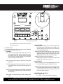
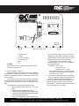
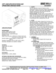
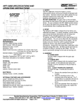
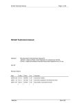
MPT-250A SPECIFICATIONS AND
OPERATING INSTRUCTIONS
DATASHEET
1. SAFETY
The MPT-250A Wire Crimp Pull Tester is a force measurement device, and as such should be operated with due caution. Operator should wear safety glasses for eye protection
because the crimp under test may break suddenly and fragments may fly off.
Do not overload: The geared motor in the pull tester can
exceed the load limits of the load cell component in this device. For your protection the MPT-250A has been factory set
to stop if the peak force exceeds 250 Lb Display blanking will
occur above 250 Lb.
2. SETUP
The Alphatron MPT-250A is shipped from the factory
precalibrated and tested. To assure consistent, correct results,
users should familiarize themselves with the setup and operation of the unit before placing it in service.
To operate, set the MPT-250A on a flat, level surface in an
upright position. Do not handle, pick up or move the unit by
exerting leverage against any front or rear panel controls, fixtures or connections. Always lift by the base plate, preferably
at the mid point along either side. DO NOT use the Lower Grip
as a handle for lifting or moving the MPT-250A. This can result
in permanent damage to the load cell sensing unit.
MPT-250A MOTORIZED WIRE CRIMP PULL TESTER
SPECIFICA
TIONS
SPECIFICATIONS
PERFORMANCE
Capacity: 250 Lb (113Kg) (1112N)
Safe Overload: 120% of capacity
Readout Accuracy: ± 0.8%
Resolution: 1 Lb
Speed Control Accuracy: ±1/8"/min. @ 1-5"/min. rate of pull
±1/4"/min. @ 6-10"/min. rate of pull
Standard Display: Pounds (XXX)
Optional Display: Kilograms (XX.X), or Newtons (XXX)
Operating Temperature: 50°F to 100°F (10°C to 38°C)
Auto-stop enable/disable switch
3. ASSEMBLY
3.1 LOWER GRIP
The MPT-250A is shipped with the standard lower
grip installed. If an optional lower grip was ordered,
it will be necessary for the purchaser to install it.
PHYSICAL
Weight: 26 pounds, less options.
Height: 8 inches
Width: 10 inches
Depth: 15 inches
Cabinet: Painted carbon steel
ELECTRICAL
Power: 115VAC, 50/60 Hz standard (230VAC 50/60 Hz optional)
OPTIONAL FEATURES AND ACCESSORIES
Display units in Kilograms
Lb/Kilograms switching
Display units in Newtons
Lb/Newtons switching
Kg/Newton Switching
7.5-30"/min. selectable rate of pull in ten 2.5"/min. increments
Ring Terminal lower grip
Adjustable setpoint for motor stop at preset force
RS-232 output
230VAC 50/60 Hz operation (International Power Cord
Configuration)
Slotted screw adjustment for Zero - Replaces standard knob
adjustment
3.1.1 Vertical Terminal Grip (optional)
To install the Vertical Terminal Grip, proceed as follows:
A. Unscrew the screw holding the Self-Tightening
Cam-Type Lower Grip in place.
B. Place the screw in the mounting hole in the Vertical Terminal Lower Grip.
C. Screw the assembly firmly into place on the load
cell sensing unit.
3.1.2 Ring Terminal Lower Grip (optional)
If the Ring Terminal Lower Grip option has been ordered, installation is as follows:
A. Remove the screw holding the standard lower
grip in place.
B. Substitute the optional grip for the standard grip
and tighten the screw until the lower grip rotates
DANIELS MANUFACTURING CORP., 526 THORPE ROAD, ORLANDO, FL 32824, USA
PHONE (407) 855-6161 • FAX (407) 855-6884 • WWW.DMCTOOLS.COM • E-MAIL: [email protected]
COPYRIGHT © 2001 ALL RIGHTS RESERVED
PAGE 1 OF 6
REV. C
05/01
FILE # DS0033
DOC # MPT-250A-DS
DATASHEET
LBS
WIRE CRIMP TESTER
PRINT
(optional)
N
(optional)
200 LB MAX CAPACITY
ZERO
RESET
MOTOR CONTROL
START
IN
OUT
HI
6
LOW 1
LO
RESET
7
2
RATE OF PULL
INCH/MINUTE
8
3
STOP
AUTO STOP
ENABLE
CRIMP GRIP
DISABLE
9
4
10
5
1
MEASURE
(optional)
SET
(optional)
MPT-250A FRONT VIEW
with resistance but is not loose or does not need
to be forced to turn.
4. OPERATION
In the instructions that follow operation of both standard
and optional features will be covered.
4.1 POWER
4.1.1 Check the operating voltage of the unit. The correct operating voltage is on the identification label
on the back of the unit. Be sure that this voltage is
the same as the voltage available at your location
before you plug in the MPT-250A.
4.1.2 Turn the power switch in the center of the back
plate OFF.
.
4.1.3 Plug the power cord into its receptacle on the back
of the MPT-250A, and into the incoming power receptacle.
4.1.4 Turn the power switch ON. The display on the front
panel will turn on and the Motor Control Stop Switch
will be lighted.
4.1.5 Allow 15 minutes warm-up before making valid
tests.
4.2 LOWER GRIP
4.2.1 Depress the operating lever of the Self-Tightening
Cam-Type Lower Grip to open it far enough to accept the sample under test. When you release the
lever it will grip the sample.
4.2.2 (Optional Grip) Rotate the lower grip to place the
correct slot for the wire/terminal under test in the
uppermost position. Select a slot that is the same
width as the wire diameter, or one size larger.
4.2.3 Ring Terminal Lower Grip (optional)
Rotate the grip to place the correct stud uppermost
and place the terminal over the stud.
4.3 UPPER GRIP
4.3.1 If the upper grip is not positioned as shown on the
Front Panel drawing press the RESET button.
4.3.2 Depress the operating lever of the Self-Tightening
Cam-Type Upper-Grip to open it far enough to accept the sample under test. When you release the
lever, it will grip the sample.
4.4 FRONT PANEL CONTROLS
4.4.1 Motor Controls:
A. START — motor start switch to begin test.
DANIELS MANUFACTURING CORP., 526 THORPE ROAD, ORLANDO, FL 32824, USA
PHONE (407) 855-6161 • FAX (407) 855-6884 • WWW.DMCTOOLS.COM • E-MAIL: [email protected]
COPYRIGHT © 2001 ALL RIGHTS RESERVED
PAGE 2 OF 6
REV. C
05/01
FILE # DS0033
DOC # MPT-250A-DS
DATASHEET
B. RESET — resets peak hold meter to approximate zero and resets pull wheel to START position for the next test. Reset must be performed
after each test.
NOTE: The peak hold meter does not always
return to an exact zero reading. If the meter reads
less than .5 Lb (in the Lb mode) continue testing. If the figure is greater than .5 Lb depress the
RESET switch next to the display. This should
clear the residual peak value. If it does not, adjust the meter ZERO (see section 4.6.2)
C. STOP — Stops the motor, and the meter retains
the current peak value.
4.4.2 AUTO STOP — This feature stops the pull test
when the piece under test fails. When the force applied to the piece under test peaks and then falls
below 70% of the displayed reading, the test is completed and the unit stops.
The ENABLE/DISABLE switch will have the following effect:
ENABLE = AUTO STOP works.
DISABLE = AUTO STOP does not work (the STOP
switch must be used at the completion of a test).
NOTE: The AUTO STOP function will not operate if
the test range is at or below approximately 4.5 to 6
Lb. This is necessary to allow for the preload that
an operator will normally apply when inserting a connector for the test. If the preload is greater than the
lower limit, the unit will not start. In this circumstance it is necessary to decrease the preload and
depress the meter RESET switch in order to be able
to start the test.
If the test involves loads (connections) that will part
at a force less than the lower limit, AUTO STOP
does not function. Press the MOTOR CONTROL
STOP switch to stop the test when the connection
breaks.
4.5 RATE OF PULL CONTROLS
4.5.1 LO-HI switch
A. LO selects rate of pull of 1-5 in./min.
B. HI selects rate of pull of 6-10 in./min.
4.5.2 1-5 switches select rate of pull between 1-5 in./
min.(LO), or 6-10 in./min. (HI) as chosen by setting
of LO-HI switch.
4.6 DISPLAY CONTROLS
4.6.1 RESET - Resets the display (clears peak values)
to zero. Use this switch when making zero adjustments.
4.6.2 ZERO - Adjusts the display to true zero. When
turned counterclockwise the meter will not read a
number greater than -001. Press meter RESET after each increment turned to arrive at zero. Several
adjustments may be necessary to reach exact zero.
4.6.3 Lb/kg Switch (optional), switches the display to
indicate pounds force of kilograms as the unit of
measure.
4.6.4 Lb/N Switch (optional), switches the display to indicate pounds force or newtons as the unit of measure. Decimal point switching is automatic.
4.6.5 *Kg/N Switch (optional), switches the display to
indicate Kg force or newtons as the unit of measure. Decimal point switching is automatic.
4.7 OTHER OPTIONAL CONTROLS ON THE
FRONT PLATE
4.7.1 PRINT push-button. Activates RS-232 output to
serial printer or other RS-232 compatible device.
4.7.2 The SETPOINT option enables an operator to program the force at which the MPT-250A is to stop
automatically if the test proceeds to that force and
the connection under test does not fail.
NOTE: When setting the force for the setpoint, the
display reading is in Lb only. For systems using
kilograms or Newtons as the unit of measure a conversion factor must be applied.
1 lb = .454 kg
1 lb = 4.448 N
SETPOINT/MEASURE when held in the MEASURE
position enables the operator to select the setpoint
by turning the SET adjusting knob next to the switch.
As the knob is turned, the setpoint force will be indicated on the peak hold meter. Clockwise adjustment increases the setpoint value, and turning the
knob counterclockwise decreases the value.
The force reading from the load cell is disabled, and
will not be enabled until the switch is in the
SETPOINT (raised) position.
Tests are conducted with the switch in the raised
position. When the load reaches the setpoint level,
the motor will stop and the unit can be reset and
reloaded for the next test.
This option can be used in conjunction with the AUTO
STOP feature. When both features are turned on,
the test will stop automatically if either condition is
met (AUTO STOP, or SETPOINT).
If the peak reading of the force necessary to part a
connection is desired, the setpoint should be at 199.9
Lb before testing. A connection requiring more than
DANIELS MANUFACTURING CORP., 526 THORPE ROAD, ORLANDO, FL 32824, USA
PHONE (407) 855-6161 • FAX (407) 855-6884 • WWW.DMCTOOLS.COM • E-MAIL: [email protected]
COPYRIGHT © 2001 ALL RIGHTS RESERVED
PAGE 3 OF 6
REV. C
05/01
FILE # DS0033
DOC # MPT-250A-DS
DATASHEET
that peak force to part will cause the digital display
to go blank and the unit will stop automatically without a peak reading.
4.7.3 The CONSTANT FORCE option operates similarly
to the SETPOINT option. An additional switch is
provided above the SET knob. The switch should
be set to PEAK for normal operation, and to CONTINUOUS when using the CONSTANT FORCE option.
4.8 SPECIAL FEATURES
4.8.1 Optional Digital Output Board — RS-232.
When the optional RS-232 Digital Output Board is
installed in the MPT-250A, it is necessary to set a
series of output parameters by means of the 8 switch
DIP package installed on the board.
REMEMBER: you must switch the unit off each time
any switch settings are changed in order to have
them take effect when you restart the MPT-250A.
4.8.1.1 Switch Location
To gain access to the Digital Output Board switches
it will be necessary to remove the left hand cover
(when looking at the front of the machine) which is
held in place by two screws at the base plate. The
Digital Output Board is the top board you will see,
and the DIP switches are on the edge nearest the
center of the machine.
4.8.1.2 Dip Switch Settings:
See Tables Below
4.8.1.3 The RS-232 output wiring of the D-connector on
the back panel of the MPT-250A is as follows:
Auxiliary Connectors Pinouts
Pin 2 = (Rx) Receive
SWITCH
#1
Closed
Closed
Open
Open
SWITCH #3
Closed
Closed
Closed
Closed
Open
Open
Open
Open
#2
Closed
Open
Closed
Open
#4
Closed
Closed
Open
Open
Closed
Closed
Open
Open
DECIMAL POINT
xxxx (1)
xxx.x
xx.xx
x.xxx
#5
Closed
Open
Closed
Open
Closed
Open
Closed
Open
BAUD RATE
9600 (1)
4800
2400
1200
600
300
300
300
SWITCH
SWITCH
#6
Closed
Closed
Open
Open
#7
Closed
Open
Closed
Open
LB
KG
N
LB
(Pounds) (1)
(Kilograms)
(Newtons)
(Pounds)
#8
Not used
(1) Factory Settings (MPT-250A)
Pin 3 = (Tx) Transmit
Pin 5 = (CTS) Normally high, goes low at start, high
at stop
Pin 7 = Signal Ground
Pin 24 = Remote Switch enable (normally open,
momentary contact).
Pin 25 = Signal Ground for Remote Switch.
RS-232 I/O Port pin functions
Pin 2 Rx received data Data to MPT-250A
Pin 3 Tx transmitted data Data from MPT-250A
Pin 5 (CTS) Normally high, goes low at start,
high at stop
Pin 7 SG Signal GND
Pin 24 Remote switch enable (normally open, momentary contact)
Pin 25 Signal ground for remote switch.
13 12 11 1 0
9
8
7
6
5
4
25 24 23 22 21 20 19 18 17 16
RS-232 General Specifications
Communications System: .... Full duplex serial
Definition: ............................ DCE
Baud Rate: .......................... Selectable - 300, 600, 1200,
2400, 4800, 9600
Start Bits: ............................ 1
Data Bits: ............................ 8
Parity: .................................. None
Stop Bits: ............................ 1
Coding: ................................ ASCII
Transmission Sequence: ..... LSB first
End of Trans. Delimiters: ..... CR LF
4.8.2.4 RS-232 Output Format
Data will be transmitted in response to any received
character on the Rx port or by pressing the PRINT
button on the MPT-250A.
Character
1
2
3
4
5
Space (for positive sign)
Digit
Digit or decimal point
Digit or decimal point
Digit or decimal point
DANIELS MANUFACTURING CORP., 526 THORPE ROAD, ORLANDO, FL 32824, USA
PHONE (407) 855-6161 • FAX (407) 855-6884 • WWW.DMCTOOLS.COM • E-MAIL: [email protected]
COPYRIGHT © 2001 ALL RIGHTS RESERVED
PAGE 4 OF 6
REV. C
05/01
FILE # DS0033
DOC # MPT-250A-DS
DATASHEET
R-CAL
FUSE
ON
OFF
AUX. OUTPUT
AC POWER
MPT-250A
MADE IN U.S.A.
MPT-250A REAR VIEW
6
7
8
9
10
11
Digit or space
Space
Units (L K Space)
Units (B G N)
CR
LF
4.9 FUSE
If the main fuse requires replacement install a .3 Amp.
125/250V slow blow fuse.
5. FUNCTIONAL CHECK
The MPT-250A Wire Crimp Pull Tester is factory calibrated
with equipment traceable to the NIST. It is a recommended
practice to recalibrate the unit at intervals not to exceed one
year in duration.
The functional check is executed using the R-cal switch
located behind the swing-away cover on the back plate of the
unit and its R-cal value is on the sticker on the switch cover
plate.
A functional check can be performed at any time:
1. Allow the MPT-250A to warm up for 15 minutes.
2. Depress the reset toggle momentarily.
3. Zero the display by alternatively turning the zero
knob and momentarily pressing the reset toggle
until the display reads 000.
4. Press the R-cal button on the back of the unit
(under the swing-away cover). Press the reset
toggle to zero the display. Repeat this process
several times to assure a repeatable value. The
display value (R-cal # X .005 = tolerance)
R-cal # plus & minus tolerance = range
should be within +/-.5% the value recorded on
the swing-away cover.
EXAMPLE: R-cal = 144
144 X .005 = 0.72
143.28 to 144.72 = range
Note: Round answers to closest number that
can appear on the display. In this example,
the range is 143 to 145.
5. If any of the procedures in steps 2-4 do not produce the expected results, the unit should be
returned to DMC for repair and recalibration.
6. NOTE: On testers with switchable display units,
first select proper units (Lb, Kg, N), then perform steps 2-4. Switching units after performing
an R-cal may affect your reading.
DANIELS MANUFACTURING CORP., 526 THORPE ROAD, ORLANDO, FL 32824, USA
PHONE (407) 855-6161 • FAX (407) 855-6884 • WWW.DMCTOOLS.COM • E-MAIL: [email protected]
COPYRIGHT © 2001 ALL RIGHTS RESERVED
PAGE 5 OF 6
REV. C
05/01
FILE # DS0033
DOC # MPT-250A-DS
DATASHEET
Special information for Self-Tightening Cam-Type
Lower Grip users:
When you install the Self-Tightening Cam-Type
Lower Grip the R-cal number may be different than
the one that is on the sticker.
For your convenience we suggest that after the
optional grip is installed, take an R-cal reading and
record it for use as the R-cal factor for this particular
machine.
LIMITATION OF LIABILITY / LIMITED WARRANTY*
DANIELS MANUFACTURING CORPORATION IS NOT LIABLE FOR CONSEQUENTIAL OR SPECIAL DAMAGES OF ANY NATURE OR KIND RESULTING FROM THE USE
OF ANY OF ITS PRODUCTS. OWNERS AND USERS OF DMC PRODUCTS ASSUME
FULL RESPONSIBILITY FOR INSTRUCTING THEIR EMPLOYEES IN THE PROPER AND
SAFE USE OF SUCH PRODUCTS.
Daniels Manufacturing Corporation warrants each new unit sold by it to be free from
defects in material and workmanship under normal use and service. Its obligation under this
warranty is limited to the free correction or, at its option, the refund of the purchase price of
any such unit which proves defective within ninety (90) days after delivery to the first user,
provided that the unit is returned with all transportation charges prepaid, and which shall
appear to its satisfaction, upon inspection by it, to have been defective in material or workmanship. This warranty shall not cover any damage to such products, which in the opinion of
Daniels Manufacturing Corporation, was caused by normal wear, misuse, improper operation or accident. This warranty is in lieu of all other warranties express or implied. No
warranty, express or implied, is made or authorized to be made or assumed with respect to
products of Daniels Manufacturing Corporation, other than that herein set forth.
*as defined by PL93-637
DANIELS MANUFACTURING CORP., 526 THORPE ROAD, ORLANDO, FL 32824, USA
PHONE (407) 855-6161 • FAX (407) 855-6884 • WWW.DMCTOOLS.COM • E-MAIL: [email protected]
COPYRIGHT © 2001 ALL RIGHTS RESERVED
PAGE 6 OF 6
REV. C
05/01
FILE # DS0033
DOC # MPT-250A-DS