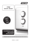
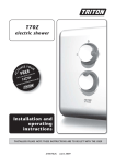
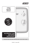
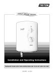
1
Part No. 404-0119
Issue 01/02
Installation Instructions
& User Guide
NewTeam Electric Shower
In the event of a query, please contact the
NewTeam Customer Helpline by calling:
01536 264 012
NewTeam Limited,
Brunel Road,
Earlstrees Industrial Est
Corby,
Northants.
NN17 4JW
Please keep this booklet for future reference.
Dear Installer,
When you have read these instructions
please ensure you leave them with the user.
Product Features
Product Features
Contents
Installation & Operating Instructions for
NewTeam Electric Showers
1. Reduce Temperature Indicator
Indicator light to show when the temperature
selection is too high.
1
Please read this booklet carefully and ensure the installation is undertaken by a
competent person.
2. Low Pressure Indicator
Indicator light to show low incoming water
pressure.
2
3. Standby Indicator
Status light for standby informs the unit is
ready for operation.
Please note:
Following the headings in sequence will guide you through the installation and
operation of your NewTeam Electric Shower.
3
4. Power Control
Adjustable power settings: Cold, Medium
and High.
4
5. Temperature Control
Adjustable Temperature Control
Planning Your Installation
5
2
Fitting Your Shower
• Plumbing Connections
• Electric Connections
• The Unit
• Riser Rail, Hose and Handset
3-5
User Instructions
7-10
Trouble Shooting
10
Spare Parts Listing
11-12
Guarantee
13
Refer to back cover for Guarantee, Customer Service and Replacement Parts
Policy. In the event of any query regarding installation, please contact NewTeam
Customer Service Department. Tel: 01536 264 012, Fax: 01536 409 201.
In line with our policy of continual product development, the specifications may be varied and product design
altered. We reserve the right to depart from the details given in this manual without prior notice.
1
NewTeam Electric Shower
NewTeam Electric Shower
2
Planning your Installation
Fitting your Shower
Plumbing (Fig. 1)
If the shower is to be installed in a hard water area, we recommend that an in-line
scale reducer is fitted. Please refer to your supplier for advice.
The installation must comply with all Water Authority and Building Bye-laws and
regulations.
Options
To ensure the correct operation of this shower, it must be installed to a mains
cold water supply with a minimum running pressure of 1.0 bar (14.5 PSI) using
15mm pipework (see Fig. 1).
• The pipework can enter the shower from the left or right of the shower unit.
• If using the inlet connection to the left, the pipework can enter from the top,
bottom or rear.
This shower can be supplied from a cold water storage tank, providing there is a
minimum static head of 10 metres from the base of the storage tank, to the
handset position. If this option is taken it must only be on a totally dedicated
supply to the shower.
• If using the inlet connection to the right, the pipework can only enter from the
bottom or rear.
The shower must not be installed in an area subject to freezing conditions. Do
not use if you suspect the shower is frozen, this will damage the shower unit.
Changing the inlet connection from the left to the right (Fig. 2)
An additional service valve must be installed in the water supply to the shower
as an independent means of isolation for future servicing requirements.
• Lift out the outlet connection (1) from the shower unit case and bend upwards.
Do not exceed the maximum inlet pressure.
• Remove the two fixing screws and the clamp (2).
Maximum pressure
• Swivel the inlet elbow (3) solenoid assembly over to the right.
10 Bar (10 metre)
Minimum pressure (running)
Fig. 2
• Locate the assembly into the cradle and re-fix the clamp and the two fixing
screws.
1 Bar (1 metre)
Rated pressure
0 Bar
Fig. 1
• Re-position the outlet flexible into the shower unit case.
• Remove the appropriate cable/pipework access panel or insert from the
unit base.
Electrics
Warning: This appliance must be earthed.
X
X
Fitting the shower to the wall (Fig. 3)
NewTeam 7.8
Rating at 240V
Rating at 230V
7.8kW
7.2kW
Warning: Before drilling please check for any hidden pipes and cables.
• Select the position for the shower and offer the shower unit up to the wall,
marking the 3 fixing points. Drill, insert the wall plugs and secure the shower
unit to the wall.
NewTeam 8.5
8.5kW
7.8kW
NewTeam 9.5
9.5kW
8.7kW
NewTeam 10.4
10.4kW
9.5kW
The Electrical Installation and Circuit Protection of this shower must comply with
I.E.E Wiring Regulations and should be checked by a qualified electrician prior
to use.
Plumbing connections
Please note: It is important to switch off the fuse box before connecting the
cable. Please check for any hidden pipes and cables.
A separate and permanently connected cable must be taken from the consumer
unit directly to the shower via a double pole switch with a minimum contact
separation gap of 3mm. It is recommended that a residual current device (RCD)
formerly known as an earth leakage circuit breaker (ELCB) with a tripping current
of 30mA, is incorporated in the circuit.
The isolating switch can be a ceiling mounted pullcord switch within the
bathroom or wall mounted in an adjacent room. The switch must be easily
accessible and identifiable as the supply to the shower.
• Do not solder within 300mm of the shower unit or allow solder or flux to fall
onto the casings.
Fig. 3
• All plumbing connections should be completed before any electrical work is
undertaken.
Procedure
In domestic installations you must ensure that the electrical supply and existing
fuse board are adequately rated.
• Turn off the mains cold water supply and connect and run pipework to the
shower. An additional service valve must be installed for future servicing
requirements.
Important: Voltage drop in the supply to the premises, due to heavy local
demand, will affect the performance.
• Flush out the pipework prior to fitting the shower.
To ensure optimum performance and trouble-free service from your shower, care
should be taken during installation. This shower incorporates a pressure relief
device, in the unlikely event of the device discharging, it is advisable to position
the shower unit over the bath or shower tray.
3
X
• The outlet of this shower acts as a vent and must not be connected to any
tap or fitting not recommended by NewTeam Limited. Do not use any jointing
compounds during the installation.
NewTeam Electric Shower
• If pipework entry is from the rear, ensure that there is space left around the
push-fit elbow for future servicing. Bring the cold water pipe to the shower
position and connect to the inlet elbow.
NewTeam Electric Shower
4
Fitting your Shower
Fitting the Riser Rail
Spirit Rail Kit
• The inlet pipe connection into the elbow is a self-seal, push-fit type. All burrs
and rough edges must be removed from the end of the tube.
1
• If a chrome plated tube is used, remove the first 25mm of plating.
• To release the pipework from the push-fit fitting, press and hold the grey collett
against the elbow and pull the pipe out of the fitting.
Before proceeding with fitting the rail, identify each of the items supplied using
the illustration (Fig. 6).
1 6
5
4
3
2
2
The slider must not be removed from the rail during fitting. The top of the slider
has a smooth profile, whereas the underside has a recess revealing the grooves
on the handset holder.
• Turn on the supply and inspect for water tightness.
Electrical connections
3
Warning: This appliance and all connecting pipework must be earthed.
• Ensure that an earth continuity conductor is securely and permanently
connected to all exposed, metal parts of other services and appliances within
the room where the shower is installed.
4
• All cables must conform to the relevant tables within the I.E.E Regulations.
The supply cable can be surface mounted and clipped, recessed or in conduit
as detailed within the I.E.E Regulations.
No.
Part Description
1
Rail end cap
2
Sprit level
3-4
Rail with slider attached
5
Hose retainer/Gel hook
6
Screw cap
7
Hose retainer fixing screw
Rail fixing screws and
wall plugs
• Fit the hose retainer onto the bottom end of the rail and secure using the small
screw from the kit.
Procedure (Fig. 4)
7
• Ensure the electricity supply is switched off.
Fig. 4
• Run the electrical supply cable from the consumer unit via an appropriate
isolating switch and into the mains terminal block (1) in the shower unit.
5
• Connect to terminals as follows:
Live
Terminal L
Neutral
Terminal N
Earth
Terminal
6
• Drill the wall at the marked fixing position using a 6mm drill and loosely fix the
rail end, checking that the rail is hanging vertically, using the spirit level
incorporated into the top end of the rail. The bubble should be exactly between
the two lines on the spirit level body. Mark the position for the lower fixing
screw, move the rail to one side, drill the wall and fix the lower end of the rail.
• Check that the rail is vertical and tighten both fixing screws.
• The earth cable, where stripped, must be sleeved prior to connection to the
terminal block. All terminals must be carefully tightened to avoid trapping the
cable insulation with the retaining screws.
Fig. 6 - Riser Rail
• Secure the supply cable using the clamp, which is reversible for use with
6mm2 or 10mm2 cables. If a cable size greater than 10mm2 is used, the clamp
should be discarded.
• Slide the end cap into position on the top end of the rail and fit the screw
cover into the recess in the hose retainer.
When fitting the hose, the hose should pass through the hole in the hose retainer.
Note: The hose nut, not the handset handle, fits into the slider. The slider moves
more freely on the rail if gripped next to the rail, rather than at the handset.
Warning: Do not turn on the electricity supply until the cover assembly has
been replaced.
• Before fitting the cover (2) ensure power spindle (6) and temperature spindle
are in the correct position; for example, power spindle has narrow side at the
12 O’ Clock position (see Fig. 5) and the temperature spindle has locking
clicker (5) at the 6 O’ Clock position.
• Position the rail on the wall, bearing in mind the heights of people likely to use
the shower and the length of the hose when connected to the shower and
passed through the hole in the hose retainer. Mark the wall to indicate the
upper fixing screw position. Screw centres are 605mm (approximately 23
inches) apart.
Fig. 5
If the clicker has been removed then it must be refitted as follows:
• Rotate the spindle fully clockwise to the stop position.
• Fit the clicker with the aim to the left of the stop (11 O’ Clock position).
NewTeam Electric
• Offer the cover (2) onto the shower unit, ensuring that the power selector knob
indicator is pointing to the No.10 setting.
• When the power selector and the temperature knobs are correctly engaged,
push on the cover (2) and fix with the three screws (3) provided.
• Turn on the electricity supply. The standby light (4) should now be illuminated.
Please refer to ‘User Instructions’ section, to familiarise yourself with the controls before using the shower.
5
NewTeam Electric Shower
NewTeam Electric Shower
6
User Instructions
User Instructions
The Riser Rail
• If the correct showering temperature cannot be obtained, it may be necessary
to adjust the ‘Power Selector’ (2) or ‘Temperature Control’ (3) to an alternative
setting.
4
5
1
• If the ‘Reduce Temperature’ light (4) becomes illuminated, it is indicating that
the temperature setting is too high to allow sufficient water flow over the
heating elements. Lowering the temperature setting slightly will allow the
shower to function correctly. The unit may take a few seconds to reset.
The handset holder can be positioned on the riser rail, to your required height,
by gripping the slider next to the rail and sliding it upwards or downwards until
the desired position is achieved.
6
Note: The speed of reset may be affect by the incoming water temperature and
will be particularly noticeable during long spells of hot weather.
Operating the Handset
3
Fig. 8
2
• If the ‘Low Temperature’ light (5) is illuminated, it is indicating that the incoming
water pressure has fallen below the minimum requirement specified for the
correct operation of the shower. The shower heating element will turn off
automatically, to prevent discomfort for the user.
To select your desired spray mode, turn the handset levers and twist in either
direction (see Fig. 9).
• When you have finished showering, rotate the ‘Power Selector’ (2) anti
clockwise, to the ‘Off’ position.
Important - Phased Shutdown: After showering, water will continue to flow for
a few seconds to allow excess heat, stored within the electrical elements, to be
discharged. This will reduce the formation of limescale and prolong the life of
your shower.
Your NewTeam Electric Shower is supplied with a ‘Zag Variable Spray’ handset,
this handset has 3 spray modes: Spray, Jet-spray and Combination.
Cleaning the Rub-clean Handset
Fig. 7
To remove the build-up of limescale from your handset, remove the handset from
the handset holder and rub your fingers over the rubber spray jets (these can be
seen in Fig. 9). When the shower is turned on, the built up limescale will flush out
of the sprayplate.
The shower should be turned off at the isolating switch when not in use.
Note: The shower incorporates a pressure relief device; in the unlikely event that
the valve discharges water through the ‘Pressure Relief Outlet Grill’ (6), please
contact the NewTeam Customer Service Department. Telephone: 01536 264 012,
for assistance.
Troubleshooting
Understanding your Shower
Warning: Before carrying out general repairs or testing the shower, ensure that
the electricity supply is turned off at the mains and the correct circuit is removed.
• If the performance of your shower deteriorates and runs continually hot, ensure
that the handset or hose has not become restricted.
• It is the speed of water passing through the heating elements that directly
determines the showering temperature. The slower the water passes through,
the hotter the shower will be. The faster the water flow, the cooler the shower.
• The cold mains water temperature entering your property will be much cooler
in the Winter than in the Summer months. This will have an effect on the
shower setting at different times of the year.
Symptom
Likely Cause
Action/Remedy
Standby light not on.
Fuse blown.
Power supply interrupted.
Examine electrical supply to shower.
No water flow.
Isolating valve.
Power supply not on.
Turn on.
Low pressure light on.
Water pressure has fallen below the
minimum requirement.
Check running pressure.
Wait until pressure increases to 1.0 bar.
Water temperature too hot.
Insufficient water flowing through the
shower.
Clean the handset.
Increase the flow by adjusting the
temperature control knob.
Reduce the power setting.
Shower runs hot and cold
during use.
Water pressure is at minimum
requirement.
Check running pressure.
Wait until pressure increases.
Reduce temperature light
comes on.
Insufficient water flowing through the
shower.
Reduce the temperature setting
(increase flow rate).
Reduce power setting.
Water from pressure relief
outlet.
Pressure relief device operated.
Clean handset.
Is shower hose connected or twisted?
Replace if necessary.
• It will be necessary to adjust the temperature or power control settings
throughout the year to accommodate this change.
• This shower contains a stabilising valve that will minimise temperature changes
at the shower head, due to pressure variations in the incoming cold water
supply. If any fluctuation in temperature is experienced, the most likely cause
will be that other appliances are being used within the house at the same time
as the shower. If the incoming water pressure to the shower drops below the
minimum requirement of 1 bar (running pressure) the shower will automatically
turn off the power to the heating elements.
Fig. 9
Do not attempt to repair the Pressure Relief Valve Device, once activated it
must be replaced.
7
NewTeam Electric Shower
NewTeam Electric Shower
8
Preparation for First Use
Spare Parts Listing
Preparation for First Use
11
10
14
• Ensure that the ‘Power Selector’ knob is turned fully anti-clockwise to read
‘Power Setting’.
15
• Rotate the ‘Temperature Control’ knob fully clockwise.
17
16
• Turn on the water supply and inspect for water tightness.
18
• Turn on the electricity supply and the ‘Standby’ neon will illuminate.
13
• Rotate the ‘Power Selector’ clockwise, to the ‘Cold’ position. Water will flow
from the handset at minimum flow. Allow the water to run freely for 60
seconds.
• Turn the temperature knob to mid-position.
1, 2,
3, 4
5
12
6
• Rotate the ‘Power Selector’ clockwise to the ‘Medium’ position. The water
temperature will gradually increase.
12
7
• Rotate the ‘Power Selector’ clockwise to the ‘High’ position and the water
temperature will increase further.
9
• To select your ideal shower temperature, rotate the ‘Temperature Control’
clockwise to increase and anti-clockwise to decrease.
19
8
Note: When the temperature setting is adjusted, the flow rate of the water will
change, after a short time the temperature will stabilise.
• To turn the shower off, rotate the ‘Power Control’ knob anti-clockwise to the
‘Off’ position. The shower will run on for a few seconds to flush out excess
hot water from the unit and help prevent limescale build-up.
20
No.
Part No.
Description
01
SP-092-0506
7.8kW Heating Canister
02
SP-092-0501
8.5kW Heating Canister
03
SP-092-0502
9.5kW Heating Canister
04
SP-092-0504
10.4kW Heating Canister
05
SP-092-0425
PRD Cap & Shear Pad
X
X
X
X
06
SP-092-1042
Stabiliser Valve (High Flow)
X
X
X
X
07
SP-092-0423
Temperature Clicker
X
X
X
X
08
SP-092-0426
Solenoid
X
X
X
X
09
SP-092-0291
Pressure Switch Assembly
X
X
X
X
10
SP-092-0150
Low Pressure Microswitch with Lever
X
X
X
X
11
SP-092-1025
Camshaft Retention Plate
X
X
X
X
See Fig. 7
12
SP-092-0420
Phased Shutdown PCB
X
X
X
X
1 Standby Indicator
13
SP-092-1133
2 Stage Thermal Cut-out
X
X
X
X
2 Power Selector
14
SP-092-1077
Microswitch - 25 amp
X
X
X
X
3 Temperature Control
15
SP-092-1027
Camshaft
X
X
X
X
4 Reduce Temperature Indicator
16
SP-092-1085
Microswitch Operating Lever Assembly
X
X
X
X
5 Low Pressure Indicator
17
SP-092-1060
Pressure Relief Device Assembly
X
X
X
X
• The setting of the temperature control will vary in some months of the year,
due to the change in temperature of incoming mains water.
User Instructions
Control Features
6 Pressure Relief Outlet Grill
Operating your Shower (Fig. 7)
7.8 8.5 9.5 10.4
X
X
X
X
18
SP-NT-Cover Model Code
NewTeam Cover & Knob Assembly
*
*
*
*
19
SP-092-0429
Screw Brush
X
X
X
X
20
SP-092-0018
Cover Retaining Screw
X
X
X
X
X
SP-5019-WT
7.8 Base Assembly Complete
• Ensure that both the water and electricity supplies to the shower are turned on.
When the ‘Standby’ light (1) is illuminated the shower is ready for use.
SP-5020-WT
8.5 Base Assembly Complete
SP-5021-WT
9.5 Base Assembly Complete
• Rotate the ‘Power Selector’ control (2) to the desired power setting.
SP-5022-WT
10.4 Base Assembly Complete
SP-285-0023-WT
1.25 x 8mm Shower Hose
X
X
X
X
SP-168-0205-WT
Handset
X
X
X
X
SP-320-0026
Hose Washer
X
X
X
X
• Rotate the ‘Temperature Control’ (3) until your desired showering temperature
is achieved.
X
X
X
*Please state model of shower
9
NewTeam Electric Shower
NewTeam Electric Shower
10
Guarantee & Service Policy
Guarantee Card
Guarantee Card
Your Guarantee
Thank you for purchasing a NewTeam shower, designed, manufactured and tested to the highest standards by
NewTeam Ltd, to give you a long and reliable service. This product has a 2 year guarantee; 1st year parts and
labour, 2nd year parts only. This is provided that:
• The guarantee registration card is completed and returned, along with a copy
of proof of purchase, within ten 10 days.
• The product is installed and operated in accordance with our instructions and
has not been misused or damaged.
This in no way affects your statutory rights as a consumer.
Please post immediately enclosing a copy of proof of purchase.
The information on the guarantee card helps NewTeam to process any claims and contact you about your product
and its maintenance if required. The registration of your personal details is purely for Newteam use and the other
information helps us to make products for the future.
Name (Mr/Miss/Mrs):
NewTeam products are designed, manufactured and tested to the highest standards.
Address:
Should a complaint arise, products are guaranteed against faulty workmanship and materials for a period of 12
months from the date of purchase, when in domestic use.
For your guarantee to be valid, your NewTeam shower must be installed by a competent person, in accordance
with the instruction manual.
For NewTeam Use
NewTeam 7.8 ❑
NewTeam 8.5 ❑
NewTeam 9.5 ❑
NewTeam 10.4 ❑
Proof of purchase enclosed: Yes ❑ No ❑
Affix Product Label Here
This label identifies your
product and provides all the
information needed.
Postcode:
Date of Purchase:
Where Purchased:
NewTeam Ltd will repair or replace (at our option), free of charge, any faulty component during the guarantee
period, provided it has been maintained and operated in accordance with our instructions and has not been
misused or damaged.
Town:
Modification or repair of this product by persons not authorised by NewTeam Ltd will invalidate this guarantee.
This guarantee applies to products purchased within the United Kingdom or Republic or Ireland, but does not
apply to products used commercially.
NewTeam’s philosophy is to offer outstanding products with quality and
integrity, please be kind enough to help us by taking the time to answer
the following questions. Thank you.
This guarantee does not affect your statutory rights.
Marketing Information
Service Policy
1. Please state your profession:
Plumber ❑ Builder ❑ Electrician ❑ Customer ❑
Replacement Parts Policy
Important: In the event of product or component malfunction, DO NOT tamper with or remove the product from
site. Telephone NewTeam Customer Service Department on 01536 264 012 and be prepared with the date of
purchase, model number and a description of the complaint.
Our service staff are fully qualified to advise on correct installation procedures and will be able to diagnose
whether the fault will require a replacement part or a visit from a NewTeam engineer.
Other ❑ (Please specify)
2. Please state reason for purchasing shower:
New Build ❑ Replacement ❑ Renovation ❑
Other ❑ (Please specify)
If required, a service call will be booked, and either yourself or an appointed representative (who should be a
person of 18 years or over) must be present during the visit.
3. If the product is a replacement shower, please state the type and make of shower it is replacing:
All site visits to product within the guarantee period will be carried out free of any parts or labour charges provided
the conditions of the guarantee have been adhered to (second year guarantee is parts only).
All site visits to product out of guarantee will be subject to charges for parts and labour which is payable by you or
your appointed representative at the time of the visit. Charges will also be levied on cancelled appointments,
unless advised to NewTeam at least 24 hours in advance of the agreed date and time.
4. What influenced your purchase:
Advertising ❑ Trade Press ❑ Recommended by Stockist ❑ Recommended by Installer ❑
We reserve the right not to undertake work where payment cannot be made to our engineer at the time of the visit.
Other ❑ (Please specify)
NewTeam hold stocks of components for all their range of products and these will be maintained for the duration
of their life.
5. Please state your main reason for purchasing your NewTeam shower:
Should a product be discontinued, spare parts stocks will be maintained, but in the event of a part becoming
unavailable NewTeam reserve the right to supply a substitute of equal quality.
The following payment methods can be used to obtain spare parts:
• By post, pre-payment of proforma invoice by cheque or postal order.
• By telephone quoting credit card (Mastercard, Visa or Visa Delta) details.
Replacement Parts
Tel: 01536 409 222 Fax: 01536 409 201 E-Mail: [email protected]
Customer Service Hotline
Tel: 01536 264 012 Fax: 01536 409 201 E-Mail: [email protected]
11
NewTeam Electric Shower
NewTeam Product Knowledge ❑ Product Features ❑ Product Styling ❑ Price ❑
Other ❑ (Please specify)
Please tick here if you do not require any further information or product updates from NewTeam ❑
Post Back
Fold and tape as instructed overleaf.
NewTeam Electric Shower
12
Please tape down
Please tape down
3rd Fold
Affix
stamp
here
2nd Fold
✁
1st Fold
NewTeam Limited
Brunel Road
Earlstrees Industrial Est
Corby
Northants
NN17 4JW