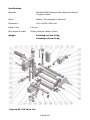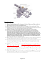
1
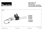
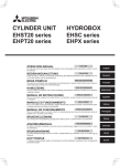
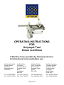
OPERATING INSTRUCTIONS
FOR
Uniprep4 Tool
63mm to 225mm
1. Machine to be operated by trained personnel.
2. Instructions to be read before use.
Hy-Ram Mansfield
Pelham Street
Mansfield
Nottinghamshire
NG18 2EY
Hy-Ram Bury
9 Portland
Industrial Estate
Portland Street
Bury
Lancashire
BL9 6EY
Hy-Ram Enfield
Unit 2, Riverwalk
Business Park
Riverwalk Road
Enfield
EN3 7QN
Hy-Ram Livingston
18 Napier Square
Houstoun Road
Trading Estate
Livingston
West Lothian
EH54 5DG
Tel: 01623 422982
Fax: 01623 661022
Tel: 0161 7641721
Fax: 0161 7620577
Tel: 0208 805 8010
Fax: 0208 805 6010
TEL: 01506 440233
Fax: 01506 440266
Page 1 of 8
Specifications.
Materials:
Mild Steel EN3A, Stainless steel, Aluminum, Brass &
Tungsten Carbide
Finish:
Natural / Zinc passivate to mild steel
Dimensions:
L320 x W130 x H220 mm
Depth of cut:
0.30 mm.
Max: length of scrape
140mm, Feed per rotation 4.5mm
Weight:
Excluding tool box 4.0 Kg
Including tool box 6.0 Kg
Uniprep 63-225 Parts List
Page 2 of 8
Number
1
2
3
4
5
6
7
8
9
10
11
12
13
14
15
16
17
18
19
20
21
22
23
24
25
26
27
28
29
30
34
35
36
37
37
38
40
41
42
44
45
46
47
48
49
Product Code
Z01-02-316
Z01-02-314
Z01-02-304
Z01-02-311
Z01-02-310
Z01-02-305
Z01-02-307
Z01-02-303
Z01-02-313
Z01-02-308
Z256-A011-018
Z01-02-010
Z01-02-011
Z01-02-012
Z183-T006-222
Z01-02-312
Z256-A011-017
Z01-02-302
Z01-02-306
Z01-02-309
Z01-02-301
Z183-T006-143
Z183-T006-157
Z183-T006-213
Z01-02-019
Z256-A011-019
Z183-T006-214
Z256-A011-004
Z256-A011-003
Z256-A008-014
Z183-T006-166
Z183-T006-158
Z183-T006-161
01-07-042
01-07-043
Z183-T006-207
Z183-T006-138
Z01-02-021
Z183-T006-130
Z183-T006-144
Z183-C048-001
Z183-T006-146
Z183-T006-159
Z183-T006-164
Z183-T006-132
Description
63-225 underarm block
63-225 undercarriage
63-225 boomerang end plate
63-225 drive handle
63-225 underarm knurled control knob
63-225 stabilizer shaft
63-225 underarm block slide shafts
63-225 axel shaft bearing spacer
63-225 drive button QR
63-225 slide shaft bottom plate
Thrust race washer
Positioning thumbscrew c/w lever
Spring tension thumbscrew 'v'
Pressure spring grubscrew
10mm x 190 st/st threaded bar
63-225 toolpost cartridge only
Thrust race bearing
63-225 axel shaft
63-225 feedscrew
63-225 toolpost carriage casting only
63-225 preptool body casting only
Screw M6 x 25 skt cap
Screw M6 x 20 c/s skt
Dome nut M10
Drive button spring (short)
o' ring 14 x 4mm
Washer M10
Undercarriage bearing 606zz
Feedscrew body & boomerang bearing 618 2 RS
Axel bearing 6301zz
Screw M6 x 40 skt button
Screw M6 x 20 skt button
Screw M6 x 25 c/s skt
Single edge tip (exp)
Single edge tip (UK)
Grubscrew M8 x 6
Screw M5 x 70 skt cap
Pressure spring (long)
Screw M5 x 16 c/s skt
Washer M6 std
Screw furniture type M6 x 16
Rod connector M6
Washer M6x20x1
Studding M6 x 35
Screw M5 x 20 skt cap
Page 3 of 8
This unit is design and manufactured to meet the requirements of National Grid Gas
Industry Standards GIS/PL2-5:2006 Part 5: Electrofusion ancillary tooling.
Hy-Ram Engineering Co Ltd has a policy of continuous improvement in product quality and
design. Hy-Ram Engineering Co Ltd therefore reserves the right to change the
specification of its models at any time, without prior notice.
It is the responsibility of the operator to ensure that the PE pipe is suitable for
pipe preparation if in doubt contact the PE pipe manufacturer for confirmation
Important!
This manual outlines the operation of the pipe surface preparation tooling for the scraping
of PE pipe prior to the electrofusion welding process.
This manual forms a part of the product to which it relates. It should be kept for the life of
the product. Any amendments issued by Hy-Ram Engineering Co Ltd should be
incorporated in the text. The manual should be passed to any subsequent holder or user
of this product.
General Description.
The pipe preparation tool is designed to provide a fusible surface on any polyethylene pipe
material (new, weathered or previously installed).
Before using
It is important to ensure all component parts are present and in serviceable condition. In
addition, the condition of the cutting / peeling tip should be checked for damage or
excessive wearing.
Safety Instructions
1. Read the instruction booklet before using the tool.
2. It is imperative that all possible precautions are made to avoid unexpected pipe
movement when the tool is being use.
3. Never use the tool on pipes that are not within the specified dimensions.
4. The tool tip holder spring tension is factory set and MUST NOT be tampered
without adequate training or instruction.
5. Operatives should wear eye protection, gloves, safety headwear & footwear when
using the equipment.
6. A single scrape / pass cannot be guaranteed to provide 100% preparation, where
this is required users are advised to consider making 2 scrapes around the pipe.
Page 4 of 8
Instructions for use.
1. Ensure that the pipe end is cut square, is free of burrs and the section to
be scraped does not have any deep scores.
2. Mark the pipe outer wall at a point 50% of the length of the coupler plus 25mm.
3. Release the tool post by loosening the tool post locking screw, position the tool post
furthest away from the undercarriage and temporarily retighten.
4. Position the scraper onto the pipe with the tool resting on the axle wheels
5. Fix the tool in its operating position by fully loosening the under arm pressure
screw, then push the underarm inward to release the ladder pin from the main
body ladder and the upwards until the wheels of the undercarriage are near to the
inner wall of the pipe. Releasing pressure on the underarm allows the ladder pin to
locate back into the main body ladder. Fixing of the tool is completed by screwing
inwards the underarm pressure screw, until the wheels on the undercarriage are in
firm contact with the inner wall of the pipe.
6. Slowly rotate the scraper around the pipe 2 or 3 times to ensure that it is positioned
correctly adjusting the underarm pressure screw to ensure ease of rotation.
7. Quarter turn the quick release thumb wheel (see reverse view) to allow the tool post
to move freely along the feed screw. Remove the protection cap from the cutter
above the mark on the pipe (see 2) a further quarter turn of the thumbwheel will
engage the feed screw-drive.
8. Quarter turn the cutter spring thumb wheel to disengage pressure on the cutter.
Release the tool post locking screw slide the tool post down until the cutter is
1-2mm from the pipe wall, and screw in the tool post locking screw to fix the
tool post in its correct operating position. Re-engage the pressure on the cutter by
a further quarter turn of the cutter spring thumb wheel. The cutter should now be
touching the pipe wall surface.
9. Rotate the scraping tool around the pipe in a steady clockwise direction. The cutter
will travel towards the pipe end removing a continuous strip of PE the process may
be halted from time to time to remove surplus peel.
Page 5 of 8
Instructions for removal after completion of pipe preparation.
1) On completion, the scraped section should be inspected for areas of un-scraped
pipe. If necessary the pipe can be scraped again.
2) To remove the scraper, loosen the tool post locking screw and raise the tool post
clear of the pipe and retighten. Loosen the underarm pressure screw to release the
undercarriage wheels and remove the scraper from the pipe. Refit the protective
cover to the cutter tip.
Storage
IMPORTANT: When not in use always –
1. Store the tool in a tool box.
2. Ensure the tool tip tension is released.
Maintenance
Lubricate all moving parts at regular intervals.
Certificate of calibration.
•
This product has been inspected and tested in accordance with the ISO9001 quality
control systems and procedures in place at Hy-Ram Engineering Co Ltd.
•
This product has no calibration period, periodic, safety inspections should be carried
out by the operator if in any doubt please contact the manufacturer for further
information
Decommissioning & Disposal Instructions
These give the instructions for decommissioning and disposal of the equipment and
confirm how it is to be taken out of service safely, in respect of the Essential Health
and Safety Requirements.
•
If a Uniprep1 tool has reached the end of its useful working life and cannot be
refurbished it must be disposed of through a licensed scrap or waste disposal
facility. Alternatively, a reverse engineering company could be used to strip the
equipment for recycling purposes.
•
Disposal is the responsibility of the Customer this can also be achieved by
returning the product back to the manufacturer.
Page 6 of 8
Warranty Information.
1.
Extent of Warranty.
(a)
Hy-Ram Engineering Co Ltd warrants to the end-user customer that its products will
be free from defects in materials and workmanship, for six months after the date of
purchase by the end-user customer, subject to providing proof of purchase.
If Hy-Ram Engineering Co Ltd receives, during the warranty period, notice of a
defect in product which is covered by this warranty, Hy-Ram Engineering Co Ltd
shall either repair or replace the product, at its option. Any replacement product
may be either new or like-new, provided that it has functionality at least equal to
that of the product being replaced.
All warranty work will be carried out by Hy-Ram Engineering Co Ltd unless
otherwise agreed. On-site warranty and repair or replacement services are
available from authorised Hy-Ram Engineering Co Ltd service facilities world-wide.
Customers shall prepay shipping charges for products returned to Hy-Ram
Engineering Co Ltd for warranty service, and Hy-Ram Engineering Co Ltd will
charge for return of the products back to the customer.
This warranty statement gives the customer specific legal rights. The customer may
also have other rights which vary from country to country in the world.
(b)
(c)
(d)
(e)
Pre-conditions for Warranty Application.
Hy-Ram Engineering Co Ltd’ warranty covers only those defects which arise as a result of
normal use of the product, and this warranty shall only apply in the following
circumstances:
(a) All the instructions contained in the operating manual have been complied with
(b) And none of the following apply:
(i)
(ii)
(iii)
(iv)
(v)
(vi)
Improper or inadequate maintenance;
Physical abuse;
Unauthorised modification, misuse or any use not in accordance with the
operating manual and good industry practice;
Operation outside the products specifications;
Improper site preparation or maintenance; and
Faulty pipe or fittings.
Page 7 of 8
Limitations of Warranty.
(a) Hy-Ram Engineering Co Ltd does not warrant the operation of any product to be
uninterrupted or error free.
(b) Hy-Ram Engineering Co Ltd makes no other warranty of any kind, whether express
or implied, with respect to its products. Hy-Ram Engineering Co Ltd specifically
disclaims the implied warranties of satisfactory quality and fitness for a particular
purpose.
(c) To the extent that this warranty statement is inconsistent with the law of the
locality where the customer uses the product, this warranty statement shall be deemed
modified by the minimum necessary to be consistent with such local law.
(d) To the extent allowed by local law, the remedies provided in this warranty
statement are the customer’s sole and exclusive remedies.
(e) This tool has been designed for the range of fittings available at the time of its
design and development. Hy-Ram Engineering Co Ltd can accept NO liability for the
unit’s ability or otherwise to work with new or different fittings that subsequently
appear in the market place.
Please complete this information and keep it safely with your proof of purchase receipt.
You will require it for any warranty claim.
Where purchased
.........................................................................................
Date of purchase
...................................................................................
Name & address
Of purchaser
...................................................................................
...................................................................................
...................................................................................
Type of tool
.........................................................................................
Serial number
...................................................................................
For Service and repair please contact:
Hy-Ram Mansfield
Pelham Street
Mansfield
Nottinghamshire
NG18 2EY
Tel: 01623 422982
Fax: 01623 661022
Page 8 of 8