1
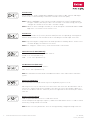
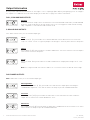
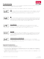
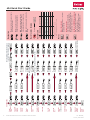
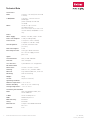
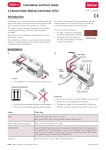
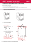
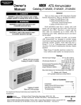
Installation and User Guide Transister Dimmer (454) Product Description The DIN rail mounted 454 is a 4-channel transistor dimmer. It can operate in one of two modes; leading edge or trailing edge. All 4 channels operate in the same selected mode, with each channel capable of controlling 2.2 A. It supports capacitive and resistive loads and can be connected directly to mains voltage lamps, and low voltage lamps with electronic transformers. The 454 is not for use with inductive loads. Each channel of the dimmer has both current and thermal protection. The dimmer features an LED 7-segment display. There is a push button user interface for monitoring, manual configuration and control purposes. Installation Location 2.1 • For installation in a restricted access location only Position & Ventilation • Install the unit horizontally to allow for heat dissipation • Any enclosure must provide adequate cooling ventilation 2.2 Electrical Do not connect DALI and S-DIM / DMX at the same time • Do not connect DALI and S-DIM / DMX at the same time • Isolate the mains supply before installation • The external supply must be protected: 10 A Type C MCB max. DALI S-DIM/DMX OVERRIDE • All DALI and Mains cabling must be 230 V mains rated MAINS SUPPLY OUTPUTS Loads 1 TO 4 • The 454 is for use with non-inductive loads only. Cable Information Cable Cable Type DALI 2-wire mains-rated. 0.5 mm² to 1.5 mm² Max. length 300 m (with 1.5 mm² cable). Example: Belden 8471 Mains cable / Dimmed outputs Max 2.5 mm² stranded (4 mm² solid). S-DIM / DMX Low-loss RS485 Type (multistranded, twisted and shielded). Note: One twisted pair for A and B (85 Ω to 100 Ω impedance), one core or twisted pair for 0 V, and shield for screen. Size: 0.22 mm² to 1.5 mm². Core: 3 or 4 + Screen. Max. Length 1000 m (lowloss cable). Example: Belden 8102 or Alpha 6222C Override 2-wire. 0.5 mm² to 1.5 mm². Max. cable length 50 m Helvar | Data is subject to change without notice. www.helvar.com i Contents SectionPage Product Description i Installationi Cable Information i Connections1 Power Up 2 Understanding the Status Display 2 Navigating the 454 Menu 3 Configuring the 454 4 Output Information 6 Troubleshooting7 ii Important Considerations 7 454 Quick Start Guide 8 Technical Data 9 Helvar | Data is subject to change without notice. www.helvar.com Connections A DA- DA+ DALI 0V SC B TERM S-DIM / DMX OVR 0V OVERRIDE DALI L N E 1 MAINS S-DIM / DMX A SUPPLY MAINS SUPPLY 0V SC B TERM Vin < 1.5 V SW Close switch to cause level override Screen (if required) DALI Note: Functional earth connection used for DALI / S-DIM / DMX screens only Devices Note: Do NOT connect DALI and S-DIM / DMX at the same time Input for override S-DIM / DMX DIMMED OUTPUTS 1 TO 4 i ii S-DIM or DMX iii i =S-DIM or DMX Data Cable (from previous device) Note: Maximum cable length = 50 m MAINS SUPPLY Note: Functional earth connection used for DALI / S-DIM / DMX screens only Lamps NON-INDUCTIVE LOADS ONLY Not for wirewound transformers S-DIM or DMX Data Cable (to next device) iii=Link for Termination (if unit is at end of S-DI DMX cable line) Note: Keep unscreened wire lengths to a minimum 1 4 DIMMED OUTPUTS 1 TO 4 Ishort = 1 mA ii = 3 OVERRIDE DALI i 2 Helvar 454 Transistor Dimmer: Installation and User Guide L Doc. 7860265, issue 4, 2014-08-28 Power Up During power up, the following sequence is displayed on the LED Control Panel. Each display is held for one second. At the end of this sequence, the ‘Status’ display appears. Start-up Sequence: 1. All segments on 2. Product model 0.5 sec 3. Software version 0.5 sec 4. Normal Operation (Status Display) 0.5 sec Understanding the Status Display The ’Status’ display is the default view in operation. It is the starting point for navigating and configuring the 454. Key and LED Descriptions: ‘Power’ S-DIM / DMX indicator activity indicator Output Software DALI Hardware mimics: override power / (wired) 1, 2, 3 & 4 indicator activity override indicator indicator ‘Power’ indicator The ‘power’ indicator (top segment of the middle digit) is always on when the 454 is powered up. S-DIM / DMX activity indicator The S-DIM / DMX activity indicator (centre segment of the middle digit) is normally off, and flashes on intermittently if any S-DIM / DMX activity (communications) is directed to a channel within the dimmer. Output mimics The output mimics (1, 2, 3 and 4) are illuminated when the dimmed outputs are on, and not illuminated when the dimmed outputs are off. Software override indicator The decimal point on the left is illuminated to indicate software override from the override test menu. DALI power / activity indicator The DALI indicator (bottom segment of the middle digit) is off if there is no DALI power, and on if DALI power is present. If any DALI activity is directed to a channel within the device, the indicator blinks off. Hardware (wired) override indicator The decimal point on the right is illuminated to indicate wired override. 2 Helvar 454 Transistor Dimmer: Installation and User Guide Doc. 7860265, issue 4, 2014-08-28 Navigating the 454 Menu The status display LEDs on the front of the unit are lit in the following way from power on: Navigate through the 454 menus using the up / down push buttons located on the front of the unit. Navigate the 454 menu to configure the unit. Cycle through the menu: 1) Press both buttons simultaneously to cycle through the menus. Tip! To cycle through the menus quickly, keep holding down both buttons. Select the desired channel to modify: 2) At your chosen function, quickly press up or down button to scroll through the channel destinations. These are the channels that will be affected by the following settings. Note: Select ALL to alter all channels simultaneously. Modify function settings: 3) Hold up or down buttons to alter the levels, settings, fade times, output modes and other settings. See section 7 for further details. + - Note: LEDs blink if the value has been changed and not yet stored. Save changes: 4) Hold both buttons together to save the change. The LEDs will show 888 for 1 second to confirm setting is stored. Return to previous screen To return to a previous screen, do not press the buttons for a short time. Back to status display 10 seconds of inactivity returns the 454 to the Status Display screen. 10 sec Tip! You can also return to the status display by cycling through all the menus. 3 Helvar 454 Transistor Dimmer: Installation and User Guide Doc. 7860265, issue 4, 2014-08-28 Configuring the 454 Various settings can be configured via the control panel. Status Display / Set Channel Level Set Channel Levels (0 % –100 %) by using the push buttons in ‘Status’ menu. Select the channel(s) to change, then hold the up or down button to alter levels. For further information, refer to the ‘Quick Start Guide’ in Section 10. Note 1:You can access ‘Status Display / Set channel level’ mode whilst the device is in override mode, but it is not possible to change the channel levels. Note 2:DMX updates are disabled while using manual control. Set S-DIM / DMX Address Set the S-DIM or DMX address for each channel. Select bAS to set the S‑DIM or DMX base address. S-DIM: 252 addresses available. DMX: 512 addresses available. Set DALI Address Set the DALI address for each channel. Select bAS to set the DALI base address. DALI: 64 addresses available. Enable/Disable DMX Enable or disable DMX from this menu. When DMX is enabled (‘On’) it will use the S-DIM address. There is no channel select option; it is a global setting. Note: DMX is disabled by default. Set Dimming mode: Leading or Trailing Select Trailing or Leading edge dimming from this menu. Note: in either dimming mode, the 454 can dim only non-inductive loads. All 4 channels operate in the same selected mode. The default dimming mode is Trailing edge. Dimmed Output Table Selection The outputs can be configured to match common loads via the ‘Output Table Selection’ (‘’) menu. See table below for a brief summary of output types. For further output information please see page 8. Output Control Type Protocol t 0 Non Dim Both t t t t Linear S-DIM / DMX * Linear light with respect to control Square S-DIM / DMX * Conforms to IES Square law standard S-law S-DIM / DMX * ‘S’ shaped light curve DALI logarithmic DALI ** IEC 62386-205 SSL curve DALI ** Similar to Helvar 452 dimmer & suitable for solid state lamps DALI linear DALI ** IEC 62386-205 Output 1 2 3 4 t 5 t 6 Notes Additional information Switched on and off only Notes * Under DALI control t1, t 2, t 3 are not recommended. t 4 is used by default ** Under S-DIM control, t 4, t 5, t 6 are not recommended. t1 is used by default Minimum Fade Time Set the minimum fade time for the channels. Select the minimum fade time for each channel individually or ALL channels simultaneously. Minimum fade time can be set to: 1.00 second, 0.50 seconds, 0.15 seconds and 0.02 seconds. 4 Helvar 454 Transistor Dimmer: Installation and User Guide Doc. 7860265, issue 4, 2014-08-28 Override Level The override level can be configured for individual relay channels or ALL channels and ranges from 0 to 100. It can be manually tested via the override test function (‘Ort’) Note 1:When S-DIM/DMX is connected, the override settings in the router (configured using Designer software) will take precedence over the device’s override settings, unless you configure the software to use the device override settings. Note 2:When the unit is running in override, the left decimal point is illuminated and the middle digit of the screen flashes in the status screen. Override Test Test that the override level (set in the previous mode) functions as required, by choosing ON or OFF. The unit performs as if an override has been caused by the override input connection. Note 1:By switching this setting to ON it will not be possible to manually edit the channel levels in ‘Status Display / Set Channel Level’ menu. Note 2:To change the channel levels, ensure that override is switched off. Switch-On Level (S-DIM / DMX only) Set the Switch-on levels for S-DIM / DMX channels. S-DIM: 2 % – 64 % (Default 2 %); DMX: 0.1 % – 64 % (Default 0.1 %) Set Minimum Level (DALI only) Set the minimum level for DALI channels. DALI: 0.1 % – 100 % (Default 0.1 %) Note: The minimum level value will be overridden if the 454 is connected to a 910 or 920 router system. Hysteresis (S-DIM only) Select On or Off to activate/deactivate hysteresis. By default, hysteresis is off. When hysteresis is on, the switch-off level is 80 % of the switch-on level. At or below the switchoff level, the channel will be off. For example, if the switch-on level is 50 % and the signal rises to this level or above to turn the channel on, then if the signal falls to 40 % or below, the channel turns off. Restore to Factory Default Hold the up or down buttons for 10 seconds in this menu. The decimal points will light up in sequence, and then all LEDs will be on for 1 second to confirm that factory settings have been restored. Note: Restore to Factory Default will cause all existing manually configured settings to be lost. 5 Helvar 454 Transistor Dimmer: Installation and User Guide Doc. 7860265, issue 4, 2014-08-28 Output Information Below you will find detailed information on choosing the correct output type (T0 to T6) for your lighting system. To configure the outputs select TAB from the main status display of the 454 unit. See page 6 for further information. DALI, S-DIM AND DMX OUTPUTS Non Dim Select Non Dim for simple switch-on and switch-off of non dimmable loads. DALI, S-DIM and DMX protocols can be used with T0. All switching is at the zero-crossing point. Loads must be trailingedge compatible i.e. No inductive loads must be used. S-DIM AND DMX OUTPUTS Note: Under S-DIM control, t1 is the default output type. Linear Select Linear [T 1] if you intend to use S-DIM or DMX with a linear dim from 0 % to 100 % with respect to control. ‘Linear’ is a general purpose law that gives control of power from 0 to full power. Square Select Square [T 2] if you intend to use S-DIM or DMX with a curve that conforms to the IES Square Law. Control is from 0 to full power. S-Law Select S-Law [T 3] if you intend to use S-DIM or DMX with the output power being in an ‘S’ curve format. Note: Selecting an S-DIM curve whilst in DALI or vice versa will result in a reduced control range. DALI DIMMED OUTPUTS Note: Under DALI control, t 4 is the default output type. DALI logarithmic Select DALI Logarithmic [T 4] if you intend to use DALI with the output power following the standard DALI logarithmic curve with incandescent lamps as per IEC standard 62386-205. SSL Curve Select SSL Curve [T 5] if you intend to use DALI with a curve that works best with solid state lamps. This is similar to the Helvar 452 dimmer curve. DALI Linear Select DALI Linear [T 6] if you intend to use DALI with a standard linear function from 0 % to 100 % with incandescent lamps as per IEC standard 62386-205. 6 Helvar 454 Transistor Dimmer: Installation and User Guide Doc. 7860265, issue 4, 2014-08-28 Troubleshooting Before contacting Helvar Support, please check the following, as it may provide a solution to the problem that you have encountered, or help our support teams identify the problem. Note: Some of the following error messages are preceded by the channel which caused the error. Trip Indicates that a channel on the 454 unit has tripped. trp flashes are preceded by the channel that has been tripped. To resume normal operation on the channel, press either button on the 454 user interface. If that does not restore the trip, recycle the power to the unit. Hot Indicates that the 454 unit is getting too hot. The 454 unit will attempt to automatically reduce the output level to a safe temperature. To ensure that the unit does not get too hot, install the 454 in an area with sufficient ventilation and situate the unit at an ample distance between other units on the DIN rail. Make sure that the load per channel does not exceed 2.2 A. Trip - Temperature Indicates that the 454 unit has tripped because the unit temperature became too high. toC flashes are followed by the channel that has been tripped. This screen succeeds the Hot warning above if the 454 is unable to reduce the output level to a safe level. Trip - Loads Indicates that a particular channel (s) has tripped because the temperature has risen too fast or the wrong load type is connected. This occurs when the wrong loads are used. Check the loads connected to the 454 and make sure that they are trailing edge compatible. Do not use wirewound transformers. Communications Error (S-DIM / DMX only) Indicates a problem with the S-DIM or DMX communications. Please check wiring and terminations. Make sure that no two channels have the same addresses on the network and that the S-DIM / DMX mode is selected correctly. Important Considerations See below for other important considerations. • Do not connect DALI and S-DIM / DMX at the same time. • Some lamps may flicker if dimmed below their rated minimum level. If this occurs, change the min. level (DALI) or switch-on level (S-DIM / DMX) appropriately. If using a 910 or 920 router to control the dimmer, these settings may be changed using Helvar Designer software. • If DMX does not work, make sure that it has been switched on in the dMX menu, and then set the DMX addresses in the Ads menu. See page 6 for further information. 7 Helvar 454 Transistor Dimmer: Installation and User Guide Doc. 7860265, issue 4, 2014-08-28 8 Helvar 454 Transistor Dimmer: Installation and User Guide Return to Status Mode Restore to Factory Default S-DIM only Hysteresis Set Minimum Level S-DIM/DMX only Switch-on Level Override Test Override Level Fade Time Output mode selection Set Dimming mode Enable DMX Set DALI Address Set S-DIM or DMX Address Status / Set Channel Level 454 Power On + 10 seconds - + - + - + - + - + - + - + - + Choose Trailing or Leading (affects all channels) - + See ‘Output table’ (on this page) - + - + - - + All LEDs flash. Reset complete. When desired level has been set, wait 1 second for status screen to reappear. + Control Protocol All S-DIM / DMX S-DIM / DMX S-DIM / DMX DALI DALI DALI Output type Non Dim Linear Square S-law DALI logarithmic SSL curve DALI linear t t t t t t Under DALI control, t 4 is used. Notes ** ** ** * * Set DALI or S-DIM/DMX base addresses From the Add menu, select bAS to set the DALI base address. From the AdS menu, select bAS to set the S‑DIM or DMX base address. Variable level notice A UAr level notice occurs in certain modes if you are changing levels for ALL channels (via the ALL function) but the individual channel levels vary. Select ALL channels Where available, select, ‘ALL’ to set all available channels. ** Under S-DIM / DMX control, t1 is used. * t 6 0 1 2 3 4 5 Output Output table 10 seconds * Hold both buttons together to store the setting. Hold up or down button to alter the levels, settings, fade times, output modes (dependent on active mode). Back to status display - Press up or down button to scroll through the channel destinations. Press both buttons at the same time to cycle through the menu. Navigation 454 Quick Start Guide Doc. 7860265, issue 4, 2014-08-28 Technical Data Connections DALI: 0.5 mm² – 1.5 mm² (max. 300 m @ 1.5 mm²) S-DIM/ DMX: 0.22 mm² – 1.5 mm² low-loss RS485 Type (multistranded, twisted and shielded) Mains: Solid core: up to 4 mm² Stranded: 2.5 mm² Note: Functional earth connection used for DALI/S-DIM/DMX screens only Power Mains supply: 85 VAC – 264 VAC, 45 Hz – 65 Hz Power consumption: 2.3 W (excluding loads) Load current: 2.2 A (2.2 A × 230 V = 500 W) 4 outputs: 4 × 500 W = 2 kW) Heat dissipation: 11 W with maximum load (resistive) DALI consumption: 2 mA External protection: 10 A Type C MCB maximum The external supply must be protected Inputs Communication: DALI, S-DIM and DMX Override: Switched Input User interface: 2 push buttons for configuration Mechanical data Dimensions: 160 mm × 62 mm × 91 mm Housing: DIN-rail case; 9 module width Material: Polycarbonate/ABS mix, UL94 V–0 Mounting: DIN rail mounting Weight: 250 g IP code: 30 (00 at terminals) Operating conditions Ambient temperature: 0 °C to +40 °C Relative humidity: Max. 90 %, non-condensing Storage temperature: –10 °C to +70 °C Conformity and standards 9 DALI: DALI standard IEC 62386, with Helvar additions S-DIM: Helvar S-DIM protocol DMX: DMX512-A protocol EMC immunity: EN 61547 Safety: EN 60950 Environment: Complies with WEEE and RoHS directives Isolation: 4 kV Helvar 454 Transistor Dimmer: Installation and User Guide Doc. 7860265, issue 4, 2014-08-28