1
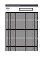
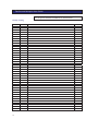
Twinflex and Multipoint
User Guide
26-0340 Issue 1
1
Twinflex and Multipoint User Guide
Rafiki Protection Limited
Rafiki policy is one of continual improvement and the right to change a specification at any time without notice is reserved. Whilst every care
has been taken to ensure that the contents of this document are correct at time of publication, Rafiki shall be under no liability whatsoever in
respect of such contents.
2
Twinflex and Multipoint User Guide
Contents
Introduction
.
.
.
Purpose of the guide
.
Definitions
.
Responsible Person
Competent Person
Understanding the equipment
System configuration
.
What to do if!!! .
.
The fire alarm sounds
The buzzer sounds
.
.
.
.
.
.
.
.
.
.
.
.
.
.
.
.
.
.
.
.
.
.
.
.
.
.
.
.
.
.
.
.
.
.
.
.
.
.
.
.
Installation Details
.
.
.
.
6
.
.
.
.
.
.
.
.
.
.
.
.
.
.
.
.
.
.
.
.
.
.
.
.
.
.
.
.
.
.
.
.
.
.
.
.
.
.
.
.
.
.
.
.
.
.
.
.
.
.
.
.
.
.
.
.
7
7
7
User Responsibilities
.
.
.
.
Introduction
.
.
.
.
Routine testing .
.
.
.
Daily .
.
.
.
Weekly .
.
.
.
Quarterly
.
.
.
Annual .
.
.
.
Action by the User after a fire
.
Action by the User after any false alarm
Action by the User following a fault
.
.
.
.
.
.
.
.
.
.
.
.
.
.
.
.
.
.
.
.
13
13
13
Log Book
.
.
Event log
.
Weekly testing .
Routine maintenance
Modifications
.
.
.
.
.
.
.
.
.
.
.
15
15
17
19
22
.
.
Operation
.
.
.
Normal
.
.
Access Levels. .
.
2 and 4 zone panels
8 zone panels
.
Fire Alarm
.
.
On hearing the alarm
.
Accessing the controls
.
Silencing the alarms
.
Resetting the system
.
Sound alarms (evacuate) .
Silence buzzer
.
Exit Access Level Two .
Trouble shooting .
.
.
.
.
.
.
.
.
.
.
.
.
.
.
.
.
4
4
4
4
5
5
7
7
8
8
8
8
8
9
9
3
Twinflex and Multipoint User Guide
Introduction
Purpose of the Guide
This guide is provided to enable the person responsible for the fire alarm system (see Definitions) to
operate the system, undertake their responsibilities with regard to testing and maintenance of the
system, and to record events and service/maintenance visits.
This is a generic document and therefore refers to the system components in general terms only. The
details of the installed system should be recorded in the space provided within this guide, and for
further reference, the record drawings (if applicable) should be consulted.
The responsible person, and any other staff who may be required to operate the system in an
emergency, should read and understand the basic operating instructions before an emergency
situation occurs.
Definitions.
Responsible person;
The person having control of the premises, whether as an occupier or otherwise, or any person
delegated by the person having control of the premises to be responsible for the fire alarm
system and the fire procedures.
Competent Person;
A person competent to perform a defined task.
Normally a competent person will be an employee of the manufacturer, installer, or servicing
contractor, or servicing contractor, or a member of the user’s staff who has received suitable
training from the manufacturer or supplier.
Understanding The Equipment.
What is Twinflex?
Twinflex is the name of the range of control panels and associated devices which together form the fire
alarm system installed in the premises, and is derived from the method of wiring whereby trigger
devices (detectors and call points) are connected to the same pair of wires, unlike the majority of
systems which employ separate circuits for detectors and sounders.
Advantages of the Twinflex system are a significant reduction in cabling costs and a neater installation.
What is Multipoint?
This is the name of the automatic detector used in the Twinflex installation. The Multipoint is a unique
device which provides several modes of detection and sensitivity options within a single device,
enabling it to be easily configured for the application. One detector can function as a smoke detector or
heat detector (or both), and with various levels of sensitivity to suit the environment.
4
Twinflex and Multipoint User Guide
The Multipoint detector also incorporates an integral sounder for general alarm annunciation or a local
warning as required.
What is Checkpoint?
Checkpoint is a feature of the Twinflex plus range, which provides configuration options suitable for
applications involving residential premises such as apartments, hotels and HMOs (houses of multiple
occupation). Checkpoint panels are identified by the ‘Checkpoint’logo on the panel fascia.
System Configuration
The detectors and call-points are arranged in zones to enable the location of a fire alarm to be
identified. The number of zones depends on the size and the layout of the premises, and the capacity of
the control panel. The number of zones on the panel (2, 4, or 8) is the maximum capacity available and
may not be the number of zones installed, i.e. there may be less. There should be a chart or drawing
provided with the system indicating the area and layout of the zones – ensure that you are familiar with
the zone layout so that appropriate action can be taken in the event of a fire alarm.
The system may be interfaced with the building services, e.g., the air conditioning may be shut down
when the alarm sounds. Make sure that you know what happens when the fire alarm operates as this
can affect routine system testing.
The system is powered from the mains supply and incorporates a standby battery which automatically
maintains the system in operation for a time of at least 24 hours in the event of a mains supply failure.
What to do if . . .
The fire alarm sounds;
CARRY OUT THE PRESCRIBED FIRE DRILL
When it is safe to do so silence the alarms and reset the system, having first established the cause of the
alarm (refer to Operation).
The buzzer sounds;
If the buzzer sounds without the alarm sounders operating it is likely to be a fault or other abnormal
condition.
Make a note of all illuminated LEDs and displayed messages, record the time that the condition
occurred (if known), and other events within the building, eg., power failure, contractors working, etc.,
(Refer to troubleshooting).
Call the service company with as much information as possible.
5
Twinflex and Multipoint User Guide
Installation Details
This section should be completed by the commissioning engineer at handover.
Name of Responsible Person:
……….….………………………………………………………..………….
Name and address of installation: ………………………..……………...……………………………………….
.…………………………………………………………….……………………………………………………….
Ref. No. (if applicable):
……….…………………………………………………………………………………
Date of Handover:
……….…………………………………………………………………………………
Name and address of installer:
…………...………...…………………………………………………………
.…………………………………………………………….……………………………………………………….
Tel:
………………………………….……………………………………………………………………..…..
Fax:
………………………………….…………………………………………………………………………
Equipment:
Control Panel:
Twinflex / Twinflex plus
No. of zones used:
2 / 4 / 8
No. of detectors:
………………………………………………………………….………………………
No. of call-points:
………………………………………………………………….………………………
No. of sounders:
………………………………………………………………….………………………
Interfaces:
………………………………………………………………….…………….
Mains Supply:
………………………………………………………………….…………….
In an emergency call:
Normal Hours:
Out of hours:
6
………………………………………………………………….………………………
………………………………………………………………….…………….
Twinflex and Multipoint User Guide
General Operation
Normal
In the normal operating mode only the green POWER LED is lit. If any other LEDs are lit and/or the
buzzer is sounding there is an abnormal condition present.
Access Levels and Soft Keys
In normal operation the panel controls are inoperable, to prevent unauthorised operation (ACCESS
LEVEL 1 – Normal Level).
In order to operate the panel following a fire or fault alarm, or for routine testing, the controls must be
enabled by entering ACCESS LEVEL 2 (User level).
2 and 4 Zone Panels
Press the ALT button and then enter the access level 2 code (514).
N o t e . The 3-digit access code is advised at handover - ensure that it is known to all personnel who
may be required to operate the panel.
The CONTROLS ENABLED LED is lit and the controls are enabled.
Note. The panel reverts to normal operation (access level 1) if no button is pressed for 5 minutes - or
enter access code again to immediately revert to access level 1.
8 Zone Panel
Set the key-switch to ON.
The CONTROLS ENABLED LED is lit and the controls are enabled.
Note. Turning the key-switch OFF reverts to access level 1
There is a third access level which is used by engineers to access engineering functions and
configuration options, but is not required for general functions and is therefore not described in this
guide.
Fire Alarm
A fire alarm is annunciated when a detector detects smoke or heat, a manual call point is operated, or an
input is active. The subsequent actions depend on the actual configuration but generally:
- the alarms sound
- the FIRE LEDs are lit
- the buzzer pulses quickly
- the relevant zone LED is lit
The panel indicates if the activated device is a detector or a call point.
7
Twinflex and Multipoint User Guide
On Hearing the Alarm
The responsible person should have already prepared written procedures for the action to be taken in
the event of a fire alarm. When the alarm sounds these procedures should be implemented.
Silencing the Alarms
When the fire procedures have been carried out and it is safe to silence the alarm, proceed as follows:
Set the panel to access level 2 (see above).
Press button 1.
The ALARMS SILENCED LED is lit and the buzzer continues to pulse. The alarm sounders are
muted.
Note . If another device is activated on a different zone, e . g. by the fire spreading, the alarms will
resound and the new alarm is displayed.
Resetting the System
Before attempting to reset the system the cause of the alarm should be established. An activated
detector is indicated by its LED being lit, and a call point can be identified by the broken glass.
The system will not reset if the cause of the alarm is still present, e.g. smoke or heat in the vicinity of a
detector or broken glass in a call point.
Set the panel to access level 2.
Press button 2.
Note. The alarms must be silenced before the panel can be reset.
Sound Alarms (Evacuate)
To activate the sounders at any time, or after they have been silenced, proceed as follows:
Set the panel to access level 2.
Press button 3.
The panel displays a fire condition and activates the sounders.
To silence the sounders, silence alarms and reset the system as described previously.
8
Twinflex and Multipoint User Guide
Silence Buzzer
The buzzer can be silenced as follows:
Set the panel to access level 2.
Press button 4.
The BUZZER SILENCED LED is lit. The buzzer will continue to sound intermittently as a reminder
that an abnormal condition exists.
If the panel does not reset or a fault condition is displayed, call the service engineer.
Troubleshooting
Problem
Unable to silence alarms
Possible Cause
Panel not set to ACCESS LEVEL 2
Unable to reset system
Alarms not silenced
Panel not set to ACCESS LEVEL 2
Alarm condition still present
Buzzer sounding, FAULT
LED lit
Buzzer sounding,
POWER FAULT LED
flashing,
Buzzer sounding,
SYSTEM FAULT LED
lit
Fault or abnormal condition
Mains supply failure
Control panel fault
Remedial Action
Enter access code (2/4 zone panel ‘514’) or
operate key-switch (8 zone panel)
Silence alarms before attempting to reset
the system
Enter access code (2/4 zone panel ‘514’) or
operate key-switch (8 zone panel)
Remove cause of alarm, eg., replace broken
glass in call point
Note all illuminated LEDs. Call engineer
Wait until mains supply is restored – if
panel does not revert to normal operation
call engineer.
Call engineer immediately
9
Twinflex and Multipoint User Guide
User Responsibilities
Introduction
The responsible person is required under BS5839 to undertake certain tasks with respect to the testing
and maintenance of the fire alarm system. The responsible person should also ensure that written
procedures are in place for the actions to be taken by the occupants in a fire condition, and that staff
required to operate the system have received adequate training. In a small building the fire procedures
can be quite simple, but when larger premises are involved the fire procedures can become more
complex and may involve the appointment of fire wardens, reporting procedures, various assembly
points, etc.
The responsible person is also required to liase with the building maintenance personnel to ensure that
their work does not impair or otherwise affect the operation of the fire alarm system, and to ensure that
a clear space is maintained in the vicinity of detectors, and call-points remain unobstructed and
conspicuous.
Routine Testing
The responsible person should also ensure that the following routine testing is carried out. If there is a
link to a remote monitoring center it will be necessary to advise the center prior to a test, or use the
control panel facilities to isolate the link. On larger systems it may be necessary to isolate building
services interfaces to avoid disruption to the occupants. In any case the panel should provide audible
and visual indication that parts of the system are disabled.
Daily
Check that the panel indicates normal operation and that any fault is recorded. Also check that the
recorded faults have been dealt with.
Weekly
At least one detector or call point should be operated to test the ability of the control equipment to
receive a signal and sound the alarm.
In practice it is far easier for the user to activate a manual call point, rather than a detector which
requires special equipment. A different device should be tested each time if possible, such that each
zone on the system is tested at least once in a 13 week period.
The results should be recorded in the log book.
Quarterly
‘The responsible person should ensure that every three months the following check is carried out by a
competent person’
In other words the system should be checked by a fire alarm service organisation. This may be the
system installer or an approved maintenance company, and is normally arranged via a maintenance
agreement which specifies the number of visits and the level of service. The agreement should also
cover non-maintenance visits, eg. call outs to attend faults, etc.
10
Twinflex and Multipoint User Guide
The standard specifies a number of maintenance tasks which include a visual inspection of the
installation to ensure that there are no alterations or obstructions which could affect the operation of the
system, and functional checks to confirm the operation of the system.
Any defects should be recorded in the log book and reported to the responsible person. A certificate of
testing should also be completed and given to the responsible person.
Annual
The requirements of the annual test are similar to the quarterly test except that each device on the
system should be tested. Different service organisations may undertake device testing on the same visit,
ie. One major service and three minor service visits per year, or they may test a percentage of the
devices on each visit so that they are all tested within the 12 month period.
Action by the user after a fire
Advise the servicing company and arrange for the system to be tested by them. A certificate of testing
should be issued to confirm the system operation following the inspection and any remedial work that
is necessary.
Action by the user after any false alarm
The user can assist the servicing company in the identification of false alarms by observing the
following:
x
x
x
Always make a note of all illuminated indicators and messages displayed at the control panel.
Try and identify the activated device, ie. Do not reset the system until the area of the incident
has been inspected.
Record any other incidents occurring at the same time which could affect the system, eg.
power supply failure, building works, etc.
The service organisation will be more likely to trace the false alarm if the above information is
available.
Action by the user following a fault
When a fault is reported by the control panel, the user should note all illuminated LEDs, and the
circumstances at the time the fault occurred, and report to the servicing company.
The service company will be able to advise if the system is still able to respond to a fire alarm or
whether extra vigilance should be observed until the fault is rectified. Faults should not be left
unreported.
11
Twinflex and Multipoint User Guide
Log Book
Record all fire and fault events,
whether or not an engineer was called
Event Log
Date
12
Time
Zone/Device
Event
Action
Initials
Twinflex and Multipoint User Guide
Date
Time
Zone/Device
Event
Action
Initials
13
Twinflex and Multipoint User Guide
Test the alarm each week using a different call point in rotation.
All call points should be numbered for identification
Weekly Testing
Date
14
Point No
Comment
Initials
Twinflex and Multipoint User Guide
Date
Point No
Comment
Initials
Date
Point No
Comment
Initials
15
Twinflex and Multipoint User Guide
16
Twinflex and Multipoint User Guide
Date
Point No
Comment
Initials
17
Twinflex and Multipoint User Guide
Record all routine maintenance
visits and note parts used/ replaced
Routine Maintenance
18
Date
Comment
Initials
Date
Comment
Initials
Twinflex and Multipoint User Guide
Date
Comment
Initials
19
Twinflex and Multipoint User Guide
Date
20
Comment
Initials
Twinflex and Multipoint User Guide
Date
Comment
Initials
21
Twinflex and Multipoint User Guide
Modifications
22
Twinflex and Multipoint User Guide
Date
Description of Modification
Contractor
Complete
23
Twinflex and Multipoint User Guide
24