1
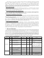
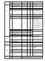
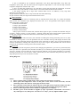
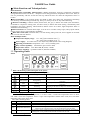
NA6830 User Guide
3 Main Function and Technique Index
Main Function:
) Refrigeration Controlling (Refrigeration / heat): temperature showing, temperature controlling
(refrigeration/heat mode can be set),compressor start delay protection, temperature sensor error alarm, it
can run periodically with the on-off rate and stop which has been set when the temperature sensor is
broken.
) Fan Controlling: 7 fan running modes: fan ahead or delay start, delay stop, temperature controlling
start and stop, time controlling start and stop, always on, always off, run or stop when defrosting.
) Defrost Controlling: 2 defrost modes (electric heat, hot gas), 3 defrost start mode (time alternation,
accumulative compressor running time, real time clock), 2 defrost end mode (timing, controlled by both
temperature and time), dripping, manual defrost, defrost sensor error alarm, high temperature alarm is
forbidden when defrosting.
) External alarm: one external alarm input, it can be set to 5 modes: always open, always open locked,
always closed, always closed locked or forbidden.
) Real Time Clock (RTC): Internal RTC, it is still running when power off, and it supplies an accurate
time, used for real time defrost.
Main Technique Index:
2 Temperature display range: -50~150℃(The resolution is 0.1℃)
-58~302℉(The resolution is 0.1℉)
2 Power supply: AC 220V±10% or AC 380V±10% 50Hz (Refer to the wiring diagram)
2 Operating environment: temperature -10℃~50℃, humidity≤85%.
2 Relay contact capability: 8A/250VAC (pure resistive load)
2 Temperature sensor: NTC R25=5kΩ, B (25/50) =3470K
2 Executive standard: Q/320585 XYK 01 (NA6830-CTDFA)
Operating Guide
Panel:
*
What’s the meaning of the index lights on the panel?
The function of the LED on the panel is showing below:
Index Light
Name
Light
Flash
Temp Setting
In the state of temp setting
-
Refrigeration
Refrigerating
Heat
Heating
Defrost
Defrosting
Ready to refrigerate, in the state of compressor start delay
protection
Ready to heat, in the state of compressor start delay
protection
Dripping or the state of compressor start delay protection
Fan
Fan running
-
Alarm
-
Alarm state
*
The meaning of the LED display
The LED usually shows temperature, if it shows “SHr”, it means the temperature sensor is short,
and “OPE” means the temperature sensor is open. The temperature and the alarm code (Axx) will show
alternately when in the alarm state.
The code is showing below:
*
Code
A11
A21
Signification
External alarm
Temperature sensor error
A22
Evaporator sensor error
A99
Over probation time
Explanation
Alarm from external alarm signal, please refer to the internal parameter code “F50”
Open or short(showing “OPE” or “SHr”)
Open or short(showing “OPE” or “SHr” when press the key “”). If you don’t
need to use the evaporator sensor, you can use the F59 to close the alarm.
If you have set the probation time F87, the alarm occurs when the accumulative
running time is over probation time, and the controller can not work.
How to set the temperature?
1
Press the key “set” for at least 2 seconds, then enter the state of temperature setting, here the LED
displays the setting temperature, then using “” key or “” key can change the parameter(the
key“”adds 0.1°C, the key“”minuses 0.1°C, press and hold it over 0.5 seconds can add or minus
rapidly). After setting, press “set” again, then exit the state of parameter setting. (The setting temp range is
limited by the parameters F13 and F14, please refer to the advanced operation). Pressing the key “M” in the
setting process means cancel and exit, but the setting value will not be saved.
* How to defrost manually?
When in the state of displaying current temperature, press the key “” and hold it at least 5 seconds,
then the controller enters the defrosting state. In defrosting state, press the key “” and hold it at least 5
seconds again, this can finish the defrosting forcibly.
* How to read the temperature of the evaporator sensor?
When displaying current temperature, press “” key, Controller will display evaporator temperature.
Loose “” key, then return to current temperature. Notice that if you press the key and hold it for 5
seconds, the controller will enter or exit the defrosting state forcibly.
* How to look over and adjust the real clock time?
Press the key “Set” to enter the state of displaying time when in the state of displaying temperature.
Press the key “Set” for some time to enter the state of adjusting time, and press the key “Set” to return to
the state of displaying temperature.
In the state of adjusting time, the hour part of the LED flashes, and you can adjust the hour by using the
key “” and “”, then press the key “Set”, and the minute part of the LED flashes, you can also use the
key “” and “” to adjust the value, then press the key “Set” again to exit. Pressing the key “M” in the
adjusting process means giving up and exiting, but the time will not be saved.
* How to refrigerate (or heat) forcibly?
When displaying current temperature, the temperature is between “setting temperature-temperature
difference” and “setting temperature+temperature difference”, the system may or not refrigerate, here you
press the key “” and hold it for 5 seconds, the controller will enter the refrigeration state forcibly when in
the refrigeration state, and stop refrigeration when the temperature is below “setting temperature-
temperature difference”; the controller will enter the heat state forcibly when in the heat state, and stop
heating when the temperature is above “setting temperature+temperature difference”.
9 Advanced Operation
Press the key “M” and hold it for 5 seconds, and if you have set the password, the LED display the
“PAS” to hint you to enter the password, you can use the key “” and “” to enter the password, if the
password is correct, the LED will display the parameter code, use “” or “” to select the parameter
code,Pressing the “set” key can make it to show the value of the parameter after select the parameter, here
you use “” or “” to set the parameter(pressing the key and not release can add or minus rapidly), then
press the “set” key to return to the state of showing parameter code after finishing setting. Pressing the key
“M” can exit the parameter setting state when display the parameter code, pressing the key “M” means
cancel when in the process of setting parameter, and the parameter will not be changed.
Internal parameter code is showing below:
Sort
Code
Parameter Name
Range
Factory
setting
Unit
Remark
F14 – F13
0
℃/
℉
The setting range is limited by F13
and F14
Control the temperature difference,
please refer to the temperature
controlling
Notice: the controller will follow
the rule of F14<F11<F13
forcibly, if you find out that one
parameter can not be adjusted, it
is because the parameter is
limited by other parameters, you
must first adjust other parameters
Adjust the evaporator sensor bias
F11
Setting temperature
F12
Temperature difference
0.1 – 20
1.0
℃/
℉
F13
Max setting temperature
-58 - 302
302
℃/
℉
F14
Min setting temperature
-58 - 302
-58
℃/
℉
F18
Evaporator sensor adjustment
-20 – 20
0.0
F19
Temp sensor adjustment
-20 – 20
0.0
0 -- 10
3
min
0 -- 10
3
min
0 -- 100
0
%
Temperature
Compressor
F20
F21
F22
Compressor delay when power
on
Compressor delay time
Compressor running frequency
when error
℃/
℉
℃/
℉
Adjust the temperature sensor bias
Enable when the temperature
sensor is error
2
F23
F29
F31
Defrosting
Compressor on/off cycle when
error
Compressor controlling mode
(temp controlling mode)
Defrost alternation time
(Enable when F35=1 and 2)
F32
Defrost end temperature
F33
F34
Defrost end time
Dripping time
5 -- 999
60
min
COOL / HEAT
COOL
-
0.1 – 99.9
12
hour
0.0 – 50.0
15.0
1 -- 99
0 -- 99
30
5
℃/
℉
min
min
F35
Defrost start mode
OFF
1 -- 3
1
-
F36
Defrost stop mode
0 or 1
1
-
F37
Defrost heat mode
0 or 1
0
-
F38
Fan state when defrosting
OFF or ON
OFF
-
F41
Fan mode
OFF
1 -- 6
1
-
F42
F43
Fan ahead / delay start time
Fan delay stop time
0 -- 999
0 -- 999
30
0
F44
Fan start temperature
-58 -- 302
-10
F45
Fan start temp difference
0.1 -- 50
5
F46
F47
Fan start time
Fan stop time
0 -- 999
0 -- 999
10
10
sec
sec
℃/
℉
℃/
℉
min
min
Fan
F50
External alarm mode
0 -- 4
0
-
YES / NO
YES
-
Alarm
F59
RTC
System
setting
F60
F61
|
F66
Testing
Enable when F41=1 and 2
Enable when F41=3 and 4
Enable when F41=5
0: without external alarm
1: always open, unlocked
2: always open, locked
3: always closed, unlocked
4: always closed, locked
00:00—23:59
6 Real Time defrost start
time(Enable when F35=3)
00:00—23:59
OFF
OFF
-
OFF
0001 -- 9999
OFF
-
OFF means no password
0000 means clearing password
C/F
C
-
C: Centigrade
F: Fahrenheit
-
-
hour
-
-
-
Password
F81
Temperature unit
F86
OFF: defrost is off
1: time alternation start
2:time alternation start, the
alternation
is
compressor
accumulative running time
3: RTC start
0:only controlled by time
1:controlled by both time and temp
0: electric heat 1: hot gas
OFF: fan off when defrosting
ON : fan on when defrosting
OFF: fan off
1:follow the compressor state, fan
delay start, delay stop
2:follow the compressor state, fan
ahead start, delay stop
3:fan is controlled by the
evaporator temp, start when low
temp, stop when high temp
4: fan is controlled by the
evaporator temp, start when high
temp, stop when low temp
5:fan is on when the compressor is
on, and times to start and stop
when the compressor stops
6:fan always running
Whether use the evaporator
sensor error alarm
Set the RTC time
F80
F85
COOL: refrigeration mode
HEAT: Heat mode
Display accumulative running
time
Accumulative running time
reset
F87
Probation time
F98
Reserved
F99
Test self
OFF
1 -- 9999
-
OFF
hour
OFF means not using
The controller will stop if the
accumulative
time
is
over
probation time, and show the
alarm code “A99”.
OFF means no probation time
This function can attract all relays in turn, and please don’t use it
when the controller is running!
3
End
Exit
7 Basic Operating Principle
Temperature controlling
The controller has 2 temperature controlling mode: Refrigeration and Heat(F29).Temperature
controlling point is controlled by “setting temperature (F11, or press the “set” key for some time to set)”
and “temperature difference(F12)”.In refrigeration mode, the controller begins to refrigerate when the
temperature of the temperature sensor is over “setting temperature + temperature difference”, and it stops
refrigerating when the temperature is under “setting temperature - temperature difference”; In heat mode,
the controller begins to heat when the temperature of the temperature sensor is under “setting temperature
- temperature difference”, and it stops heating when the temperature is over “setting temperature +
temperature difference”.
Compressor delay when power on
The compressor delay when power on is set by F20, for example, 3 minutes, the controller does not
start the compressor within 3 minutes after power on.
Compressor delay time
The compressor delay time is set by F21, for example, 3 minutes. The controller contains a
“compressor halt calculagraph”, and it begins to time when compressor stops, the program first check the
calculagraph before booting the compressor next time, the program will immediately boot the compressor
if the calculagraph reach 3 minutes ,if the calculagraph doesn’t reach 3 minutes ,it will boot again when the
calculagraph reaches 3 minutes. Thus you can ensure that the boot alternation is over 3 minutes after halt,
so it can prevent to breaking the compressor as a result of frequent boot.
Compressor running timly when temperature sensor is error
When the temperature sensor is error, in order to avoid that the goods in the coldroom destroy, you can
make the compressor continues to run with a setting on/off rate. It is set by F22 and F23, for example,
F22=20, F23=50, that when the temperature sensor is error, the cycle is 50 minutes, and the compressor
stops for 40 minutes and runs for 10 minutes.
Auto defrosting principle
The controller has 3 defrost start modes which can be selected(F35):
OFF: Defrost is off.
1. Time alternation: the controller will start defrost according to the setting alternation time which can
be set in “Defrost alternation time (F31)”.
2. Accumulative compressor running time: if compressor accumulative running time reaches the time
which set in “defrost alternation time (F31)”, the controller starts defrost.
3. RTC start: the controller turns on defrost according to the actual time (for example, 6:00 AM), 6
points can be set at most (F61-F66), in this mode, “defrost alternation time (F31)” does nothing.
The controller has 2 defrost end modes which can be selected(F36):
0: time control: the defrost time can be set by F33, the controller will stop defrosting when it reaches
the defrost time.
1: controlled by both time and temperature: the controller will check the defrost effect through
evaporator sensor after starting defrost, If the sensor temperature reaches the “Defrost end temperature
(F32)”, the controller will turn off defrosting, if the defrost time is longer than “defrost end time (F33)”, the
defrosting will be turned off forcibly.
You can select 2 defrost heat modes (F37):
0: electric heat: the compressor stops and the defrost output is turned on (the defrost output controls
the electric heater);
1: hot gas: the compressor and defrost output is turned on (the defrost output controls the valve).
Dripping
A dripping time can be set (F34). For example, set the dripping water with 5 minutes, after finishing
defrosting, in 5 minutes, compressor doesn’t run, in this state, “Defrost” indicator light will flash. But in
two conditions the controller can’t enter the dripping state: one is finishing the defrosting manually, and the
other is defrosting temperature sensor’s error.
About fan controlling
Fan has 7 operation modes (F41):
OFF: fan is off, but it may start when defrosting (rest with F38)
1: follow the compressor state, fan starts lingeringly after compressor starts (F42), fan stops
lingeringly after compressor stops (F43).
2: follow the compressor state, fan starts ahead before compressor starts (F42), fan stops lingeringly
after compressor stops (F43).
3: fan is controlled by the evaporator temperature, start when low temperature, stop when high
temperature (F44, F45), the fan starts when the evaporator temperature is below F44 and stop when the
evaporator temperature is over F44+F45.
4
4: fan is controlled by the evaporator temperature, start when high temperature, stop when low
temperature (F44, F45), the fan starts when the evaporator temperature is over F44 and stop when the
evaporator temperature is below F44-F45.
5: fan is on when the compressor is on, and times to start and stop when the compressor is off, the
on/off time is set by F46 and F47, in other words, on for F46 minutes and off for F47 minutes.
6: fan always running, but it stops when external alarm occurs. In addition, it may stop when
defrosting (rest with F38).
In spite of which mode, fan state is only rested with F38 when defrosting.
In spite of which mode, fan stops when external alarm occurs.
External alarm
The controller can connect a switching value as external alarm source (Pin 4, 5), when the external
alarm occurs, the controller stops, displays the alarm code “A11” and generates alarm output. External
alarm signal has 5 modes (F50):
0: without external alarm
1: always open, unlocked
2: always open, locked
3: always closed, unlocked
4: always closed, locked
“Always open” means in normal state, external alarm signal is open, if closed, the controller will give
an alarm; “Always closed” is on the contrary. “Locked” means that when external alarm signal becomes
normal, the controller is still in the alarm state, and it needs to press any key to resume.
Probation time
A probation time can be set (F87), the controller can add up the running time after power is on, if the
accumulative running time is over the probation time, the controller will stop and display the alarm code
A99, if you want to eliminate the limit of probation time, set the F87 to “OFF”, also you can use the F86 to
clear the accumulative running time, and you can try to use it again. The parameter F85 can be used to
examine the accumulative running time of the controller (hour).
Password
In order to prevent irrespective persons from changing the parameters, you can set a password (F80),
and if you have set a password, the controller will hint you to enter the password after you press the key
“M” for 5 seconds, you must enter the correct password, and then you can set the parameters. If you don’t
need the password, you can set F80 to “OFF”. Notice that you must remember the password, and if you
forget the password, you can not enter the set state.
Wiring Diagram:
Notice:
1. Please read the guide carefully before using, and set the parameter accurately.
2. Please place the temperature sensor at the place of air return of the air-cooler, and the
defrosting sensor above the air return pipe of the air-cooler.
3. The evaporator sensor must be fixed on the air return pipe of the evaporator, and if you don’t
use the evaporator sensor, please set the F59 to NO, or the controller will generate alarm.
4. Please use the temperature sensors which are supplied by our company.
5. The RTC power of the controller is supplies by super capacitance, and the RTC can run for 3
days when power cut, if the power cut time is over 3 days, you may adjust the RTC again.
5