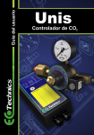
1
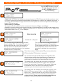
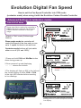
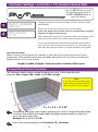
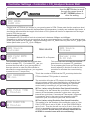
D
o
se
User Guide
o
w
id
e
er
D
ay
Revision: DEC 5th 2012
n
bo
CO2
Accurate
Sensing
H
E
v
o
lu
ti
o
n
P
o
w
er
D
ay
D
o
se
GAS FLOW RATE
O.17 lpm
U
P
D
O
W
N
F
an
S
E
T
U
P
H
or
tic
u
E
ltu
r
v
o
al
lu
C
ar
ti
o
n
December 2012
Added new section - Page 16
New section - page 30
D
P
io
x
Carbon Dioxide Controller
Fan
Multi-Language
Support
Timer
Introduction
Thank you for purchasing the Ecotechnics Evolution Carbon Dioxide Controller.
In order to take full advantage of your new controller, please read this manual
carefully and use the product as directed.
Carbon dioxide (CO2) is a colourless, odourless gas that occurs naturally in our
environment. It is normally present in the atmosphere at an average concentration of
approximately 0.00036% or 360 PPM.
Many growers fail to recognise the importance of Carbon Dioxide in their growroom.
Most plants grow faster and larger with enhanced CO2 levels because of more efficient
photosynthesis and a reduction in water loss. There are also many other benefits for plants,
among them greater resistance to temperature extremes and other forms of stress, better
growth at low light intensities, improved root/top ratios & less injury from air pollutants.
Photosynthesis is the term used to describe the process by which plants combine CO2
molecules with water molecules to form complex sugars. There is a resultant spare oxygen
atom which is released back into the air. The sugars are then further processed by the plant
to form natural polymers for growth. The ambient level of CO2 in air is 300-400 PPM, which
fast growing plants in your growroom or glasshouse can use all the available CO2 in less
than an hour, slowing photosynthesis and bringing growth to a virtual halt.
Your new Evolution controller utilizes the latest microprocessor and infrared technology to
monitor & control the levels of carbon dioxide in your growing area.The controller can
operate with or without the optional Evolution Solid State NDIR CO2 sensor and can also be
used with either bottled CO2 gas or with a propane or natural gas burning CO2 generator.
In addition to this the Evolution controller can be interfaced to most external thermo /
hygrostats for improved environmental control.
It can be seen that the rate at which plants are able to grow is relative to the availability of
photosynthesized complex sugars. Raising the ambient CO2 level in your growroom causes
more sugars to be produced allowing the plant to grow bigger and faster. The optimum level
of CO2 for plant growth is dependant upon many different factors such as light levels ,
temperature, humidity and nutrient availability. Plants grown with enhanced CO2 can grow
up to 40% faster thus shortening crop times and increasing yields. This is of course
assuming there are no other limiting factors such as lack of available light etc.
It should be noted that there is generally no advantage to increasing CO2 levels beyond
3000 PPM for most greenhouse plant species. It should also be noted that there is generally
no advantage to raising CO2 levels during dark hours.
1
Controller & Accessories
The Evolution CO2Controller
Your new Evolution controller utilizes the latest microprocessor and
infrared technology to monitor & control the levels of carbon dioxide
in your growing area.The controller can operate with or without the
optional Evolution Solid State NDIR CO2 sensor and can also be
used with either bottled CO2 gas or with a propane or natural gas
burning CO2 generator.
In addition to this the Evolution controller can be interfaced to most
external thermo / hygrostats for improved environmental control.
The Evolution NDIR CO2 Sensor
The new solid state evolution CO2 sensor from Ecotechnics
represents the latest state of the art sensor technology utilizing
advanced solid state LED’s and detectors with precision engineered,
gold plated optics to provide high accuracy fast response real time
CO2 sensing from 0-10,000ppm
This Sensor can be purchased separately from the Evolution
controller.
Ask your retailer for further details of this product.
The Ecotechnics Carbon Dioxide Regulator
This is the perfect bottled gas regulator for use with the Evolution
CO2 Controller. We have this regulator produced for us in the UK
from top quality components it has a fixed flow rate of 17 Litres per
min. and is our standard horticultural regulator.
Ask your retailer for further details of this product.
The Evolution digital fan speed Controller
This is the perfect thermostat system to use with the Evolution CO2
Controller. It can control your extraction system and interface to the
stat input of the CO2 controller ,it can also switch up to 3Kw of heater
load for those cold winter nights.
Ask your retailer for further details of this product.
Propane CO2 Generator
There are many different propane burners available on the market
and the evolution controller can work with most of them.
Burner sizes of 0.01Kwh to 9.99Kwh are supported and the switching
output is 230Vac.
2
Controller Configuration Options
200
300
100
bar
0
400
Fan
Dose
Day
Power
DOWN
SET
UP
Evolution
Horticultural Carbon Dioxide Controller
200
300
100
0
bar
400
Fan
Dose
Day
Power
DOWN
SET
UP
Evolution
Horticultural Carbon Dioxide Controller
200
300
100
0
bar
400
Generic ON/OFF Type
Thermo / Hygro Stat.
Fan
Dose
Day
Power
DOWN
SET
UP
Evolution
Horticultural Carbon Dioxide Controller
200
300
100
0
bar
400
Fan
Heater
Fan
Temperature
Dose
Day
Min
Max
Power
DOWN
SET
UP
Evolution
Fan
Htr
Humidity
Temp
R/h
Power
Evolution
Digital Fan Speed Controller
Horticultural Carbon Dioxide Controller
3
Controller Configuration Options
Basic Open loop configuration with No CO2 Analyser
This is the simplest way to connect your controller; it only requires a power connection, a
connection to the CO2 release system and a connection to your extraction system.
In this mode the controllers internal cycle timer will periodically turn the extraction system on
and off for the programmed amounts of time. Primary dosing will occur when the extraction
system is turned off & secondary or top up dosing will occur as programmed.
For further information on setup parameters please refer to the settings section of this user
guide.
Basic Closed loop configuration with CO2 Analyser
This is the second way to connect your controller; it requires a power connection, a connection
to the CO2 release system, a connection to the Evolution NDIR CO2 Analyser and a connection
to your extraction system.
In this mode the controllers internal cycle timer will periodically turn the extraction system on
and off for the programmed amounts of time. Primary dosing will occur when the extraction
system is turned off & secondary or top up dosing will occur after the peak level minus the CO2
deadband setting is achieved.
For further information on setup parameters please refer to the settings section of this user
guide.
Configuration with an external basic ON / OFF Type Thermo / Hygro-Stat
The Evolution CO2 Controller is equipped with an interface input so that it can work in
conjunction with an external Thermostat or Thermo/Hygro-Stat. The AC Power output of the
Thermostat that normally would connect to the extractor fan should be connected to the STAT
INPUT of the CO2 Controller.
In this mode the controllers internal cycle timer will periodically turn the extraction system on
and off for the programmed amounts of time unless your external Thermo/Hygro-Stat initiates
an extraction first.
Please note, this input is an on & off type input and is not suitable for use with fan controllers
that vary fan speed, except the Evolution Digital Fan Speed Controller that has a dedicated
interface output.
For further information on setup parameters please refer to the settings section of this user
guide.
Configuration with an Evolution Digital Fan Speed Controller.
The Evolution CO2 controller is equipped with an interface input so that it can work in
conjunction with an external Thermostat or Thermo Hygrostat.
When used with the Evolution Digital Fan Speed Controller the STAT OUTPUT from the fan
controller should be connected to the STAT INPUT of the CO2 controller & the intake / exhaust
fans should be connected to the FAN 1 & FAN 2 outputs of the fan controller.
In this mode the fan controller will control the speed of the fans and will only allow the CO2
controller to dose when the fans are running at the minimum or Idle speed.
Please note this can be set to zero if desired.
For further information on setup parameters please refer to the settings section of this user
guide.
4
Controller Power Connections
N - Neutral
Technics
- Earth
CO2 Controller
L - Live
Rear view:
Back cover off for wiring connections
L
N
N
L
N
L
N
L
RJ 11
Connector
Socket
E
B
A
C
D
CO2 Input
Front View
Fan
Stat
Input
CO2
Output
Fan
Output
GAS FLOW RATE
O.17 lpm
Power
Input
Dose
Day
Power
A - Stat Input
DOWN
This input is an interface to external fan
controllers and thermostats & can be used
to implement a full environmental control
system when combined with a suitable
temperature / humidity controller such as
the Evolution digital fan speed controller.
Wire: 0.5mm - 0.75mm
SET
UP
Evolution
Horticultural Carbon Dioxide Controller
E
D
C
B
A
B - CO2 Out
D - Power Input
This is where you connect your CO2
regulator or solenoid controlled gas burner.
Please note this is a 220/240v AC output.
Please check solenoid coil voltage before
connecting. Wire: 0.5mm
This is the main power connection for the
controller.
Wire: 1.25mm -1.5mm
C - Fan Out
E - CO2 Input
This is where your extractor system is
connected. Please note that if you run
multiple fans then wire a suitable
extension socket to this output then plug
your fans into the extension. Wire: 0.75mm
This RJ 11 Socket is to plug the Evolution
NDIR Carbon Dioxide Sensor. Please note
this controller can only be used with the
Evolution NDIR Carbon dioxide Sensor
Wire: 0.5mm.
5
Secret Jardin Grow Tents- Volume chart
Dark Street II
3
DS60
0.5m
DS90
1.29m3
3
DS120
2.59m
DS150
4.56m3
Dark Room II
DR60
0.57m3
3
DR90
1.46m
DR120
2.88m3
3
DR150
4.5m
DR240
11.52m3
3
DR300
18m
DR240w
5.76m3
3
DR300w
9m
Dark Room Twin
3
DR60T
1.25m
DR120T
2.16m3
INTense
INT120
INT240
INT480
INT150
INT300
INT600
6.19m3
3
12.38m
24.76m3
3
9.67m
19.34m3
3
38.6m
6
How to set up your Controller
A
B
C
If your set up includes:
Evolution CO2 Controller + the Regulator
use Section A which starts on the next page (page 8)
If your set up includes:
Evolution CO2 Controller + the Regulator + CO2 Analyser
use Section B which starts on page 12
If your set up includes:
Evolution CO2 Controller + the Regulator + CO2 Analyser
+ the Evolution Digital Fan Speed Controller
use Section C which starts on page 16
7
section
A
User Guide:
Evolution CO2 Controller
(NO Analyser Sensor)
8
Controller Settings
Power
DOWN
1
2
SET
UP
Evolution
SELECT LANGUAGE
ENGLISH >
ROOM VOLUME
37 m3
Use the SET Button to scroll
through the menu items &
the UP / DOWN buttons to
alter the setting
Language selection screen for English, French, German, Italian
and Spanish.
Set the volume of your growing area in cubic meters.
note: your grow room volume must be entered when using the
analyser or without the analyser.
When using the Evolution CO2 Controller without the analyser it will
dose your room similar to our UNIS carbon dioxide controller..
If you have the Analyser it will take into account both the size of
your room plus the current ppm levels of CO2 in your grow room
and dose the optimum amount of carbon dioxide for your plants.
Grow Room Volume:
Before you set up your Evolution CO2 controller you will need to find out the cubic volume of your
growing area. Once calculated and set this will enable the Evolution CO2 Controller to introduce the
optimum amount of CO2 for your plants.
length x width x height = internal cubic volume of the room
Example Room Volume Calculation
The illustration below shows a typical example of a room, in this case the room
measures 5M in length, 3M in width and 2.5M in height.
Note:
If you have a Secret Jardin grow
tent we have provided a chart for
their Volumes for you on page 6
5 x 3 x 2.5 = 37.5 M 3
1
To calculate your grow room volume, measure your room in length width and height
in metres, then multiply the length width and height measurements to obtain the
cubic volume of your room.
Example: 5 x 3 x 2.5 = 37.5 M 3
2
Dial in the required setting on the Evolution CO2 Controller.
9
Controller Settings
Power
DOWN
3
SET
UP
Use the SET Button to scroll
through the menu items &
the UP / DOWN buttons to
alter the setting
Evolution
CO2 LEVEL
1600 ppm
Set the level of CO2 that you require in your growing area in PPM. Please note that the maximum level
of CO2 that a plant can process will be dependant on temperature, humidity and available light levels. It
should also be noted that the length of time that a CO2 cylinder will last for is dependant on the target
level of CO2 that you set.
Default setting is 1600ppm,
The baseline for CO2 levels in fresh air at sea level is between 300ppm and 400ppm.
Depending on which plants you are growing, the grow room temperature, humidity and at what growing
phase your plants are at (cuttings, veg and flowering) their CO2 needs can vary from no CO2 [night cycle
where plants take up no CO2 ] up to 1800ppm.
4
GAS Source
Cylinder
5
GAS FLOW RATE
17 LPM
Gas source
Bottled CO2 or Propane
6
7
TDOSE TIME
01:00 Minutes
Burner size
0.18 kWh
This controller can calculate the required
dose times for a propane CO2 generator.
For a propane gas burner you should set the
burner capacity in Kw/Hrs in order for the
controller to calculate the correct dosing
times.
This controller can calculate the required dose
times for bottled CO2 . For bottled CO2 gas you
must set the flow rate of your gas regulator in
litres per minute in order for the controller to
calculate the correct dosing times. (our regulator
is preset to use 17 ltrs per min)
TDOSE %
10 %
GAS Source
Propane
This setting is for the top up dose. The controller assumes that
after it doses CO2 into the growing area the level will gradually fall
due to a number of reasons ie: CO2 usage by plants, gas leakage
under doorways or through gaps etc. After the extractor fan turns
off the controller makes a primary dose in order to achieve the level
of CO2 enrichment required by the user, it will then wait for a
period, as specified by the user and make a small top up dose to
allow for seepage / usage of gas. This will be a percentage of the
primary dose as per this setting. Top up dosing can be disabled by
setting this option to 0%.
This setting specifies the amount of time after the primary dose that
the small percentage Top up dose occurs.
Top up dosing can be disabled by setting this option to zero.
10
Controller Settings
8
FAN CYCLE TIME
15 Minutes
9
FAN DURATION
3 Minutes
10
FAN RUNDOWN TIME
0.10 minutes
11
Stat ignore time
0 Minutes
12
DAY SETPOINT
50 %
13
RESTORE DEFAULTS
No
Yes
This setting is for the internal fan cycle timer. It controls the
amount of time between extraction cycles when using the
internal fan cycle timer. If an external Thermostat / Hygrostat
is connected, then in the event of an externally induced
extraction cycle, the internal cycle timer will be reset.
This setting is for the duration of the extraction cycle ie: if the
FAN CYCLE time is set to 30 Min & the FAN DURATION is
set to 5 min. Then the fan will turn on for 5 min’s then off for
30 min’s repeatedly unless an externally induced extraction
cycle is detected. Please note, fan duration should be set
to ZERO in a sealed room with air conditioning.
This setting allows the controller to wait for the programmed
time period from the fan output being turned off so that the
fans stop spinning before the CO2 is injected.
Please note that the time required will vary from one fan
to another and can be set to suit your particular fan.
This setting is for the Stat input & allows the controller to
ignore the stat input for the set period of time. This is useful
if your thermostat has a very sensitive deadband and
effectively will allow the fan to come on for the first time the
stat asks for it but will not allow another extraction to be
triggered by the stat until the ignore time has passed.
This setting is for the level of light at which the controller
decides to disable the CO2 output. The light sensor is
located in the front panel of the controller.
Make this setting lower to increase sensitivity.
This setting will restore all controller settings to default
parameters.
The list of default settings can be found in the specification
sheet.
Note selecting yes will result in permanent loss of all
user defined settings.
Wire connection diagram for angled plug on Regulator
Brown: Live
Blue: Neutral
Green/Yellow: Earth
11
section
B
User Guide:
Evolution CO2 Controller
+ Analyser Sensor.
12
Controller Settings - Controller + CO2 Analyser Sensor Ball
Power
DOWN
1
2
SET
UP
Evolution
SELECT LANGUAGE
ENGLISH >
ROOM VOLUME
37 m3
Use the SET Button to scroll
through the menu items &
the UP / DOWN buttons to
alter the setting
Language selection screen for English, French, German, Italian
and Spanish.
Set the volume of your growing area in cubic meters.
note: your grow room volume must be entered when using the
analyser or without the analyser.
When using the Evolution CO2 Controller without the analyser it will
dose your room similar to our UNIS carbon dioxide controller..
If you have the Analyser it will take into account both the size of
your room plus the current ppm levels of CO2 in your grow room
and dose the optimum amount of carbon dioxide for your plants.
Grow Room Volume:
Before you set up your Evolution CO2 controller you will need to find out the cubic volume of your
growing area. Once calculated and set this will enable the Evolution CO2 Controller to introduce the
optimum amount of CO2 for your plants.
length x width x height = internal cubic volume of the room
Example Room Volume Calculation
The illustration below shows a typical example of a room, in this case the room
measures 5M in length, 3M in width and 2.5M in height.
Note:
If you have a Secret Jardin grow
tent we have provided a chart for
their Volumes for you on page 5
5 x 3 x 2.5 = 37.5 M 3
1
To calculate your grow room volume, measure your room in length width and height
in metres, then multiply the length width and height measurements to obtain the
cubic volume of your room.
Example: 5 x 3 x 2.5 = 37.5 M 3
2
Dial in the required setting on the Evolution CO2 Controller.
13
Controller Settings - Controller + CO2 Analyser Sensor Ball
Power
DOWN
3
SET
UP
Use the SET Button to scroll
through the menu items &
the UP / DOWN buttons to
alter the setting
Evolution
CO2 LEVEL
1600 ppm
Set the level of CO2 that you require in your growing area in PPM. Please note that the maximum level
of CO2 that a plant can process will be dependant on temperature, humidity and available light levels. It
should also be noted that the length of time that a CO2 cylinder will last for is dependant on the target
level of CO2 that you set.
Default setting is 1600ppm,
The baseline for CO2 levels in fresh air at sea level is between 300ppm and 400ppm.
Depending on which plants you are growing, the grow room temperature, humidity and at what growing
phase your plants are at (cuttings, veg and flowering) their CO2 needs can vary from no CO2 [night cycle
where plants take up no CO2 ] up to 1800ppm.
4
GAS Source
Cylinder
5
GAS FLOW RATE
17 LPM
Gas source
Bottled CO2 or Propane
6
Burner size
0.18 kWh
This controller can calculate the required
dose times for a propane CO2 generator.
For a propane gas burner you should set the
burner capacity in Kw/Hrs in order for the
controller to calculate the correct dosing
times.
This controller can calculate the required dose
times for bottled CO2 . For bottled CO2 gas you
must set the flow rate of your gas regulator in
litres per minute in order for the controller to
calculate the correct dosing times. (our regulator
is preset to use 17 ltrs per min)
CO2 DEADBAND
50 ppm
GAS Source
Propane
This is the number of PPM that the CO2 must drop below the
CO2 level before CO2 injection is resumed.
The controller will make a CO2 dose to the target level but
will not re-dose until the level has fallen buy at least the set
deadband amount. By reducing this setting you get better
control and by increasing it you get better gas economy.
7
FAN CYCLE TIME
15 Minutes
8
FAN DURATION
3 Minutes
This setting is for the internal fan cycle timer. It controls the
amount of time between extraction cycles when using the
internal fan cycle timer. If an external Thermostat / Hygrostat
is connected, then in the event of an externally induced
extraction cycle, the internal cycle timer will be reset.
This setting is for the duration of the extraction cycle ie: if the
FAN CYCLE time is set to 30 Min & the FAN DURATION is
set to 5 min. Then the fan will turn on for 5 min’s then off for
30 min’s repeatedly unless an externally induced extraction
cycle is detected. Please note, fan duration should be set
to ZERO in a sealed room with air conditioning.
14
Controller Settings - Controller + CO2 Analyser Sensor Ball
9
FAN RUNDOWN TIME
0.10 minutes
10
Stat ignore time
0 Minutes
11
DAY SETPOINT
50 %
12
RESTORE DEFAULTS
No
Yes
This setting allows the controller to wait for the programmed
time period from the fan output being turned off so that the
fans stop spinning before the CO2 is injected.
Please note that the time required will vary from one fan
to another and can be set to suit your particular fan.
This setting is for the Stat input & allows the controller to
ignore the stat input for the set period of time. This is useful
if your thermostat has a very sensitive deadband and
effectively will allow the fan to come on for the first time the
stat asks for it but will not allow another extraction to be
triggered by the stat until the ignore time has passed.
This setting is for the level of light at which the controller
decides to disable the CO2 output. The light sensor is
located in the front panel of the controller.
Make this setting lower to increase sensitivity.
This setting will restore all controller settings to default
parameters.
The list of default settings can be found in the specification
sheet.
Note selecting yes will result in permanent loss of all
user defined settings.
Wire connection diagram for angled plug on Regulator
Brown: Live
Blue: Neutral
Green/Yellow: Earth
15
section
C
User Guide:
Evolution CO2 Controller
+ Analyser Sensor
Plus Evolution Digital Fan Speed
Controller.
16
Evolution Fan Speed & Carbon Dioxide Controllers
(CoolShade Reflector )
Nov 2012 document revision
When the 2 Evolution controllers are connected together the fans should be
connected to the Evolution Digital Fan Speed Controller as shown in the
diagram above.
Evolution Fan Speed Controller:
Enabling CON mode for fans:
Some users like to use the fan controller in CON mode when used with the
Evolution Carbon Dioxide Controller to save gas usage.
see page 18 on how to set your fan speed controller over from PHA to CON.
Evolution Carbon Dioxide Controller:
Disabling fan control on the Evolution Carbon Dioxide Controller:
Set the fan cycle timer to 1 minutes. (page 20 - step 7)
Set the Fan duration to 0 minutes to disable the timer. (page 20 - step 8)
Set the Fan Run Down Time to 0:00 minutes (page 21 - step 9)
These settings will disable Fan Control on the Evolution Carbon Dioxide
Controller and transfer control over to the Evolution Digital Fan Speed
Controller.
17
Evolution Digital Fan Speed
How to set the Fan Speed Controller into CON mode
(contactor mode) when using it with the Evolution Carbon Dioxide Controller
Advanced Settings & Calibration modes
FAN OUTPUT Mode
Some users like to use the fan controller in
CON mode when used with the Evolution
Carbon Dioxide Controller to save gas
usage.
1
Fan
Heater
Temperature
Humidity
Power
UP
Min
Max
Default is 'PHA' mode (PHAse angle
control).
Fan
Htr
R/h
Evolution
DOWN
Digital Fan Speed Controller
Phase angle mode the controller will
control the speed of the fans and you can
set a % speed for them in min and max.
Contactor mode the fans will just switch
either on or off (0% and 100%).
Temp
hold down before power on
2
Fan
Heater
1.Press and hold FAN and Min/Max button
down during power up.
Temperature
Humidity
Power
UP
Min
Max
Fan
2.Once powered up and displaying
- - - - - - release the buttons.
Htr
Temp
R/h
Evolution
DOWN
Digital Fan Speed Controller
release once the display
shows - - - - - -
3.The display will flash up E22 in the left and
the current setting of either CON or PHA
in the right LED window before reverting
to live readings.
3
Fan
Heater
Temperature
Humidity
Power
UP
Min
Max
Fan
Htr
Temp
R/h
Evolution
DOWN
Digital Fan Speed Controller
current PHA/CON mode flashes up before
settling down for normal temp and humidity
live display.
18
Controller Settings - Controller + CO2 Analyser Sensor Ball
Power
DOWN
1
2
SET
UP
Evolution
SELECT LANGUAGE
ENGLISH >
ROOM VOLUME
37 m3
Use the SET Button to scroll
through the menu items &
the UP / DOWN buttons to
alter the setting
Language selection screen for English, French, German, Italian
and Spanish.
Set the volume of your growing area in cubic meters.
note: your grow room volume must be entered when using the
analyser or without the analyser.
When using the Evolution CO2 Controller without the analyser it will
dose your room similar to our UNIS carbon dioxide controller..
If you have the Analyser it will take into account both the size of
your room plus the current ppm levels of CO2 in your grow room
and dose the optimum amount of carbon dioxide for your plants.
Grow Room Volume:
Before you set up your Evolution CO2 controller you will need to find out the cubic volume of your
growing area. Once calculated and set this will enable the Evolution CO2 Controller to introduce the
optimum amount of CO2 for your plants.
length x width x height = internal cubic volume of the room
Example Room Volume Calculation
The illustration below shows a typical example of a room, in this case the room
measures 5M in length, 3M in width and 2.5M in height.
Note:
If you have a Secret Jardin grow
tent we have provided a chart for
their Volumes for you on page 5
5 x 3 x 2.5 = 37.5 M 3
1
To calculate your grow room volume, measure your room in length width and height
in metres, then multiply the length width and height measurements to obtain the
cubic volume of your room.
Example: 5 x 3 x 2.5 = 37.5 M 3
2
Dial in the required setting on the Evolution CO2 Controller.
19
Controller Settings - Controller + CO2 Analyser Sensor Ball
Power
DOWN
3
SET
UP
Use the SET Button to scroll
through the menu items &
the UP / DOWN buttons to
alter the setting
Evolution
CO2 LEVEL
1600 ppm
Set the level of CO2 that you require in your growing area in PPM. Please note that the maximum level
of CO2 that a plant can process will be dependant on temperature, humidity and available light levels. It
should also be noted that the length of time that a CO2 cylinder will last for is dependant on the target
level of CO2 that you set.
Default setting is 1600ppm,
The baseline for CO2 levels in fresh air at sea level is between 300ppm and 400ppm.
Depending on which plants you are growing, the grow room temperature, humidity and at what growing
phase your plants are at (cuttings, veg and flowering) their CO2 needs can vary from no CO2 [night cycle
where plants take up no CO2 ] up to 1800ppm.
4
GAS Source
Cylinder
5
GAS FLOW RATE
17 LPM
Gas source
Bottled CO2 or Propane
6
Burner size
0.18 kWh
This controller can calculate the required
dose times for a propane CO2 generator.
For a propane gas burner you should set the
burner capacity in Kw/Hrs in order for the
controller to calculate the correct dosing
times.
This controller can calculate the required dose
times for bottled CO2 . For bottled CO2 gas you
must set the flow rate of your gas regulator in
litres per minute in order for the controller to
calculate the correct dosing times. (our regulator
is preset to use 17 ltrs per min)
CO2 DEADBAND
50 ppm
GAS Source
Propane
This is the number of PPM that the CO2 must drop below the
CO2 level before CO2 injection is resumed.
The controller will make a CO2 dose to the target level but
will not re-dose until the level has fallen buy at least the set
deadband amount. By reducing this setting you get better
control and by increasing it you get better gas economy.
7
FAN CYCLE TIME
1 Minutes
8
FAN DURATION
0 Minutes
SET to 1 when using Evolution Fan Speed Controller.
This setting is for the internal fan cycle timer. It controls the
amount of time between extraction cycles when using the
internal fan cycle timer. If an external Thermostat / Hygrostat
is connected, then in the event of an externally induced
extraction cycle, the internal cycle timer will be reset.
SET to 0 when using Evolution Fan Speed Controller.
This setting is for the duration of the extraction cycle ie: if the
FAN CYCLE time is set to 30 Min & the FAN DURATION is
set to 5 min. Then the fan will turn on for 5 min’s then off for
30 min’s repeatedly unless an externally induced extraction
cycle is detected. Please note, fan duration should be set
to ZERO in a sealed room with air conditioning.
20
Controller Settings - Controller + CO2 Analyser Sensor Ball
9
FAN RUNDOWN TIME
0.00 minutes
10
Stat ignore time
0 Minutes
11
DAY SETPOINT
50 %
12
RESTORE DEFAULTS
No
Yes
Set this to 0.00 minutes when using the Evolution Digital
Fan Speed Controller.
This setting allows the controller to wait for the programmed
time period from the fan output being turned off so that the
fans stop spinning before the CO2 is injected.
Please note that the time required will vary from one fan
to another and can be set to suit your particular fan.
This setting is for the Stat input & allows the controller to
ignore the stat input for the set period of time. This is useful
if your thermostat has a very sensitive deadband and
effectively will allow the fan to come on for the first time the
stat asks for it but will not allow another extraction to be
triggered by the stat until the ignore time has passed.
This setting is for the level of light at which the controller
decides to disable the CO2 output. The light sensor is
located in the front panel of the controller.
Make this setting lower to increase sensitivity.
This setting will restore all controller settings to default
parameters.
The list of default settings can be found in the specification
sheet.
Note selecting yes will result in permanent loss of all
user defined settings.
Wire connection diagram for angled plug on Regulator
Brown: Live
Blue: Neutral
Green/Yellow: Earth
21
ADVANCED
User Guide Section
22
Advanced Menus & Calibration
Section
Advanced Settings
Information Menu
Depress and hold the up button when in normal operating mode to display……
Peak CO2, Average CO2, Dose Error %, CO2 Required, Gas Generation Rate, Dose
Time & Time to Next Fan cycle.
Internal Counter Zero
Pressing the down button in normal operating mode will reset the internal counter to zero,
this function can be used to skip a fan cycle, fan rundown or CO2 dose.
Dose Calibration
1.Power turned off
2.Depress and hold the Up Button,
3.Turn the power on, with the UP button held down to enter the Dose Calibration mode.
4 Adjust the Cal factor by using the Up & Down buttons, once an adjustment has been made
5.Leave the unit alone and it will automatically store the new setting.
6.Alternatively you can store by simply pressing the Set button, this will store the offset and
enter into normal operating mode.
Note:
All green houses, grow rooms etc have a leakage rate which is dependant on many factors
such as gaps under doors gaps in glass panels etc. This setting can be used to calibrate the
dose factor to overdose a bit in order to compensate for losses. This can also be done by just
increasing the room size setting or decreasing the flow rate setting.
How to Detect which Evolution CO2 Sensor you are using
1.Power off
2.Depress and hold down the Set Button
3.Switch power on you will enter Test & Sensor Calibration mode
4.Now release the SET key
5.Depressing the Down & Up buttons Simultaneously will enter the “CO2 Calibration mode”
the screen will blank and when the buttons released you will be in “cal mode”
On this display screen in the top Left of the display is the revision number of the Sensor you
are using.
R1 = Mk1 Sensor
R2 = Mk2 Sensor
R3 = Mk3 Sensor
In the examples below you can see R3 [Mk 3 sensor] has been detected and in the second
photograph you can see that the R1 [Mk 1 sensor] has been detected.
23
Test and Calibration mode Evolution CO2 Sensor
Test and Sensor Calibration Mode for mk1 and mk2 Sensors (R1 and R2)
Please note the Evolution CO2 Sensor needs at least 15 min’s to warm up and
stabilize before calibration can be started.
1. Power off
2. Depress and hold down the Set Button
3. Switch power on you will enter Test & Sensor Calibration mode now release the SET key
4. Depressing the Down button will test the CO2 Output>> the CO2 LED will illuminate.
5. Depressing the Set button will test the Fan Output>>the Fan LED will illuminate.
6. Depressing the Down & Up buttons Simultaneously will enter the “CO2 Calibration mode” the
screen will blank and when the buttons released you will be in “cal mode”
7. CO2 Cal mode: use the down & up buttons to calibrate the Mk1 and Mk2 CO2 sensor
8. Once the correct level is programmed depress the Set button to store the new calibration setting
the display will read press SET to exit [storing your setting]
Note: ambient CO2 levels are usually 450ppm
R1 (Mk 1) sensor detected
Test and Sensor Calibration Mode for Mk3 Sensor (R3)
Please note the Evolution CO2 Sensor needs at least 15 min’s to warm up and stabilize
before calibration can be started.
1. Power off
2. Depress and hold down the Set Button
3. Switch power on you will enter Test & Sensor Calibration mode now release the SET key
4. Depressing the Down button will test the CO2 Output>> the CO2 LED will illuminate.
5. Depressing the Set button will test the Fan Output>>the Fan LED will illuminate.
6. Depressing the Down & Up buttons Simultaneously will enter the “CO2 Calibration mode”
the screen will blank and when the buttons released you will be in “cal mode”
7. Mk 3 CO2 sensor air calibration
The sensor must be positioned in outside air until stable then press the up button to
calibrate. This assumes ambient CO2 levels to be 450ppm.
Once you have entered Air Cal mode the
sensor will count down from 3mins on the
display to allow the sensor to settle on the
ambient Co2 level which it assumes is
450ppm it then stores this automatically
as the new calibration setting.
R3 (Mk 3) sensor detected
Light Level Sensor
The correct operation of the Light level sensor can also be tested in this mode and the level is
reported in the display by covering the sensor window the function can be tested.
Stat Input Test
The operation of the Stat input can also be tested by connecting your thermostats output to the
Stat input and triggering it, the state will be displayed in the top right hand corner of the
display on will show as SC and off will show as SO.
24
Specifications
25
Specifications
October 2011 Document Revisi
Settings
Controller Setting
Language
Room volume
CO2 level ppm
Default Setting
English
37 m3
1600 ppm
Range
N/A
1 - 999
600 - 3000 ppm
CO2 source
CO2 Cylinder
CO2 / Gas
Gas Flow Rate
Burner size
Fan run down
T - Dose %
T - dose Time
Deadband ppm
Fan Cycle time
Fan Duration
Stat Ignore Time
Day Set Point
Reset to Default
17 Lpm
1.8 kwh
30 seconds
10%
1 Min
50 ppm
15 Min
3 Min
0 Min
10%
Yes/No
1 Lpm - 99 Lpm
0.01 Kwh - 9.99 Kwh
30 Sec’s - 5:00 Min’s
0% - 25%
10 Sec - 30 Min
10 - 250 ppm
5 Min -60 Min
0 Min - 30 Min
0 Min - 15 Min
10% - 90%
Yes / No
Specifications
Power Supply
Power Consumption
Maximum Total Fan Load
Maximum Total CO2 output Load
220 - 240 Vac Single Phase
20 Watts Max
1.5 Kw
0.5 Kw
CO2 Measurement Range
Maximum Total combined output Load
1.5 Kw
0 - 10,000 ppm
CO2 Measurement Accuracy
+ / - 50 ppm
CO2 Measurement Resolution
1 ppm
Light Sensor
The Ecotechnics Evolution Carbon Dioxide Controller
has a light sensor as hi-lighted in the graphic on the left. This
light sensor can automatically be set to turn off the CO2
controller when it senses night time when light falls and also
turn the CO2 on when light rises back to a daytime state.
26
Typical Performance Graphs
27
Gas Regulator Safety Advice
200
300
100
bar
0
400
Only experienced and properly trained persons should handle compressed gases, they should be
conversant with relative safely instructions including the current British compressed Gases
Association code of practice CP7 and the gas safety instructions from the gas supplier.
Markings
The regulator is marked with the following:Ÿ Maximum inlet pressure (pressure service)
Ÿ Rated outlet pressure
Ÿ Gas (only use for gas shown)
Fitting to the cylinder
Before fitting the regulator, ensure both the cylinder outlet valve and the regulator inlet are clean
and free from contaminants including dirt, oil and water. If fitted, fully release the regulator
adjusting knob by winding anticlockwise prior to fitting to the cylinder. Right hand thread is
employed for oxygen and permanent gases and left hand thread is used for fuel gases. Use only
the correct size spanner and finally tighten by applying 2 blows to the end of the spanner with the
heel of the hand.
Operating
After fitting of the downstream equipment, open the cylinder valve slowly, this is a critical operation
and must be done slowly to be safe. If fitted, adjust the regulator knob to the required outlet
pressure and purge hoses, make the final adjustment when gasses are flowing. It is vital to ensure
that any audiable vibration or freezing of the regulator is avoided during operation. Check for leaks
at all joints with a leak detection spray. On completion of use, close the cylinder valve and exhaust
gas from lines.
If fitted, fully release regulator pressure adjusting knob.
Safety points
Carefully inspect the regulator for oil, grease and damaged or dirty parts. Oxygen vigorously
supports combustion, never use the regulator if oil, grease or damaged parts are detected.
Never:
Never use a regulator showing any signs of damage
Never allow cylinders to become heated
Never use pressure gauges that are damaged, not smooth in operation or not zeroing
Never remove or change any component parts of a regulator.
Always:
Always check the whole system for damage and leaks at frequent intervals
Always work to BCGA codes of practice ( to purchase copies, telephone 01491 825533)
Always fit a flashback arrestor to the outlet of an oxygen or fuel gas cylinder.
28
Safety Advice
---- ALWAYS OBSERVE THE FOLLOWING ---When connecting / disconnecting all cables, grasp the connector itself—never pull on the
cable. This way you will avoid causing shorts, or damage to the cable’s internal elements.
Do not excessively twist or bend the power cord, or place heavy objects on it. Doing so can
damage the cord, producing severed elements and short circuits. Damaged cords are fire and
shock hazards!
In households with small children, an adult should provide supervision which is essential for
the safe operation of any electrical appliances in the home.
All cords and cables should be placed so they are out of the reach of children.
Try to prevent cords and cables from becoming entangled.
Before moving the unit, disconnect the power cable from the mains supply and any cords
coming from external devices.
Never handle an AC adaptor or electrical plugs with wet hands when plugging into, or
unplugging from, an outlet or this unit.
Before cleaning the unit, turn off the power and unplug the AC adaptor from the outlet.
Do not force the unit’s power-supply cord to share an outlet with an unreasonable number of
other devices.
Be especially careful when using extension cords—the total power used by all devices you
have connected to the extension cord’s outlet must never exceed the power rating
(watts/amperes) for the extension cord. Excessive loads can cause the insulation on the cord
to heat up and eventually melt through.
Protect the unit from strong impact.(Do not drop it!)
Before using the unit in a foreign country, consult with your retailer or an authorized
distributor.
Whenever you suspect the possibility of lightning in your area, disconnect the unit from the
power outlet.
Do not attempt to repair the unit, or replace parts within it. Refer all servicing to your retailer
or an authorized distributor.
When moved from one location to another where the temperature and/or humidity is very
different, water droplets (condensation) may form inside the unit. Damage or malfunction may
result if you attempt to use the unit in this condition. Therefore, before using the unit, you
must allow it to stand for several hours, until the condensation has completely evaporated.
Please note you will find the latest revision of any of our
User Guides on the Ecotechnics website located in the
downloads area below:
http://www.ecotechnics.co.uk/downloads.htm
29
Understanding the Evolution CO2 Controller:
NEWDecember
PAGE
2012
Let’s take a closer look at understanding how the Evolution Carbon Dioxide Controller
operates in delivering Carbon Dioxide into your Grow room.
Example Grow Tent:
For this example we’ll choose a Secret Jardin DR240 as the Grow Tent we wish to use
Our Evolution Carbon Dioxide controller in.
Grow Tent size?
DR240 has a cubic capacity of 15m3. (see the chart on page 7)
Set the controller accordingly.
How much CO2 is used?
The Gas regulator has a preset Gas delivery rate of 17ltrs per minute.
Therefore with a 6 second dose, that’s 1 tenth of a minute.
So the amount of CO2 released per dose is 1.7ltrs of CO2 Gas into your grow tent.
Things to take into account:
•
•
•
•
•
•
•
•
•
•
•
•
•
•
The optimum time to dose is after an air extraction event during the day cycle.
How air tight is the grow tent?
Please Note: A leaky tent or open zips will allow the CO2 to exit the tent
How many plants are in your grow tent?
1 plant will use a small amount of CO2 but 40 plants will require much more CO2
What stage of development are your plants?
How are you distributing the gas from the regulator (perforated hose for example)
Do you have a small fan (not extraction) to stir the air in the grow tent to mix the CO2 evenly
What height do you release the CO2 in the tent?
CO2 is heavier than Air: so will tend to sink to the lower part of the grow tent in “still air” conditions.
Having an extraction event shortly a dose: CO2 will drop when air is exchanged.
No need to dose during the night cycle of the plants.
Plants do not take up CO2 in the night cycle
Using Air-cooled lighting reduces the amount of Cooling Fans in the grow room.
What the Evolution Carbon Dioxide Controller Does!
• Constantly measures/controls the level of carbon dioxide. (with analyser)
• If you wish to monitor and control the levels of CO2 use our Evolution CO2 Controller
30
SAFETY CONSIDERATIONS
F
an
Always make sure the unit is unplugged before attempting to connect the fan
and/or heater to the unit.
o
se
Always check that all cables are correctly and securely connected and that the
cover is securely screwed on before plugging the unit in and turning the power
on.
D
Always Remember that Electricity and Water is an Extremely Dangerous
Combination. Electricity can be fatal especially in the presence of water.
D
ay
It is strongly recommended that any electrical equipment used in the growing
environment is mounted above ground level, on a shelf or if possible wall
mounted so that in the event of water spillage or flooding the two remain
separate.
P
o
w
er
This appliance must be installed by an approved electrician and must be
connected via an approved RCD safety breaker.
tu
o
ra
ECOTECHNICS PRODUCT GUARANTEE
lC
lu
ti
ar
o
n
bo
n
D
io
POWER CONSUMPTION
15 WATTS MAX
SUPPLY VOLTAGE 230-240V AC
TOTAL LOAD NOT TO EXCEED 1.5kw
ul
tic
S
E
T
U
P
H
or
E
v
Thank you for choosing an Ecotechnics product for use in your growroom.
As leading manufacturers of horticultural equipment and accessories we
are committed to providing a range of innovative products to enhance your
garden. Our commitment to quality is second to none, however if you do
experience any problem all our products are covered with a full 1 year
parts & labor guarantee and should be returned to the retailer along with
the original purchase receipt .
Ecotechnics UK Ltd is not liable for labor costs involved in the installation
or removal of the product, lost profits, incidental or consequential loss,
injury to property or persons or any other consequential loss however
caused.
Purchase Date
W
N
Shop / Dealer
D
O
D D MM Y Y
Serial Number
E C
www.ecotechnics.co.uk