1
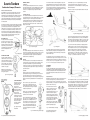
All readings on the percentage scale are based on the horizontal
distance. This means that if the distance on sloping terrain is measured
along the ground, an error is introduced and this must be corrected for
accurate results. The error is insignificant for most purposes at small
ground slope angles but increases progressively as the angle
increases.
The trigonometrical correlation is H = h x cos a where
H = the true or corrected height
h = the observed height
a = the ground angle
With the aid of the above equation, the correction can also be made in
the distance where
h = the distance measured along the ground
H = the horizontal distance sought. If the corrected distance is used, no
correction in the height observed is needed.
When calculating the horizontal distance by using the ground distance
and slope angle, it must be pointed out that an error is introduced if the
slope is measured from eye level to the pillar base. Measuring the
slope along the ground would be cumbersome and inconvenient. No
error is introduced, however, when the slope angle is measured from
eye level to a sighting mark made or placed on the pillar at eye level
(Fig. 11) whereby the two lines of measurement become parallel. the
true angle of slope is 9 degrees. The example shown in Fig. 11
illustrates both methods of calculation.
Nomographic Height Correction
When the accompanying nomogram is used, all correction calculations
become unnecessary. Only a ruler or some other convenient object
with a straight edge is needed to obtain the nomographical solution.
The nomogram is used by placing the ruler so that its edge intersects
the angle scale on the left at the slope angle point and the observed
height scale (on the right) at the pertinent point. The corrected height
(or distance) is read at the point where the edge intersects the
corrected height scale in the middle. When using a measuring distance
of 20m or 100ft along the ground, the correction procedure becomes
very simple. No slope angle measurement is then necessary. One
needs only the reading of the top point and that of the ground point.
Depending on the situation, their sum or difference gives the apparent
height directly in feet. This is then corrected as follows:
First, find on the right-hand scale in the nomogram the point indicating
the apparent height. Secondly, find on the left-hand double scale the
point indicating the ground point reading. Thirdly, connect these points.
The corrected reading will be found from the pertinent middle scale at
the point of intersection. In this procedure, the slope angle can be
neglected as the left-hand ground point scale has been constructed so
that both the ground slope angle and the average eye level height of
1.6m (5.5ft) have been taken into account.
Suunto Tandem
Combination
Compass/Clinometer
Fig.11. Calculating horizontal distance by using ground distance and
slope angle
Method 1: Measure the ground distance. This is found to be 25m (82ft).
Then measure the slope angle. This is 9°. Read percentages of top and
ground points. These are 29 and 23%.
Calculate:
29
52
23
100 + 100 = 100
Take 52% of 25m (82ft). This is 13m (42.6ft). Multiply this by the cosine
of 9°.
0.987 x 13m = 12.8m (0.987 x 42.6ft = 42ft)
Method 2: Multiply the ground distance by the slope angle cosine
(straight distance). 0.987 x 25m = 24.7m (0.987 x 82ft = 80.9ft). Add
percentage readings as above and take the sum percentage of the
corrected distance. 52 / 100 x 24.7m = 12.8m (52 / 100 x 80.9ft = 42ft).
This example shows that a slope angle of 9° causes a correction of
only 2.3% but when the slope angle is 35 degrees, the correction
means a reduction of about 18% in the observed height.
Code: 36027
Fig. 12.
ISO 9001
SUUNTO Oy’s Quality Assurance System is certified by Det Norske
Veritas to be according to the ISO 9001 in all SUUNTO Oy’s operations
(Quality Certificate No. 96-HEL-AQ-220).
Prospect House, George Cayley Drive, Clifton Moor, York, England YO30 4XE
Tel: +44 (0) 1904 692723 Fax: +44 (0) 1904 690385
E-Mail: [email protected] www.yorksurvey.co.uk
Ref:.. \operat98\instructions 15\36027.qxp 05-01-15
Operating
Instructions
©York Survey Supply Centre 2015
Suunto Tandem
Combination Compass/Clinometer
Two Precision Instruments in One!
Congratulations on your choice of the Suunto Tandem. The Suunto
Tandem is all you need for both slope/height measurements and
compass bearings. It is a liquid-filled precision compass and clinometer
in one compact aluminium housing that is easy to use and rugged
enough to protect against impact, corrosion and water. This top quality
precision instrument combines precision accuracy with fast and easy
one-hand operation.
The pocket-size construction renders the Suunto Tandem most suitable
for every type of work. Its unique shape makes it comfortable to hold in
your hand. The optics of the Tandem can be adjusted to make the
reading easier. The clinometer scale is in degrees and percent (0 - 90°,
0 - 150%) while the compass scale is azimuth (0 - 360° with reverse
scale). Both the clinometer and the compass are graduated in 1°/1%
increments and each is individually calibrated. The two edges at 90°
angle make contact measurements possible, for example, when
installing and positioning a satellite antenna.
ADJUSTING OPTICS
The optics of the Tandem can be adjusted
by turning the eyepiece with your fingers
as shown in Figure 1. Adjust the eyepiece
so that both the hairline and the scale are
sharp and the eyepiece slot settles in a
vertical position in the bearing compass
and in a horizontal position in the
clinometer.
CLEANING THE TANDEM
In the case humidity or dirt develop
inside the Tandem, it can be cleaned by
removing the detachable eyepiece. The
eyepiece can be removed by rotating it
counter-clockwise (Fig. 2). Rinse with
clean water, allow to dry and carefully
reassemble the eyepiece.
BEARING COMPASS
Construction
The bearing compass is designed to combine extreme accuracy with
ease and speed of operation. The card is supported by a jewel bearing
and is immersed in a dampening fluid, giving vibrationless, smooth
movement. The compass has been given permanent antistatic
treatment.
Inclination - Balancing
The compass card is balanced to correspond to the area within which
the compass is used. When using the compass elsewhere (e.g. on trips
abroad) the change of the vertical magnetic field could make the
compass card dip and this may cause difficulties in taking the bearing.
The balancing zone (see Fig. 4), if other than 1, is indicated on the
back of the instrument below the serial number - contact York Survey
Supply Centre for details.
Fig. 2. Removing the eyepiece
CONTACT MEASURING
The Tandem can be used
for aligning satellite dish
antennae or for other
types of contact
measuring. The clinometer
incorporates two different
contact edges (see Fig. 3)
which enable the
measurement to be made
compared to the horizontal
or vertical plane. The scale
(0 - 90 - 0 degrees) can be
used in contact measuring
and it gives the angle of
the surface compared to
the contact plane.
Fig. 3. Edges for contact
measurement
Ref:.. \operat98\instructions 15\36027.qxp 05-01-15
The task is to measure the height of a pillar at a distance of 25m (82ft)
on level ground (Fig. 8).
The instrument is tilted so that the hairline is seen against the pillar-top
(apex). The reading obtained wil be 48% (ca. 25½°). As the distance is
25m (82ft), the height of the pillar is 48 / 100 x 25 = ca. 12m (48 / 100 x
82 = ca. 39ft). To this must be added the eye’s height from the ground,
e.g. 1.6m (5½ft). Their sum is 13.6m (44½ft), the height of the pillar.
Declination
The compass reads magnetic north, which differs from true north by the
amount of the local declination which is printed on your map. In order to
lay out on a map a bearing obtained with the compass, the plus or
minus declination for the locality in question must be added to or
subtracted from the compass bearing.
Deviation
Iron and steel objects close to the compass, like a wristwatch or steelrimmed spectacles, may cause deviation. Whenever possible, remove
such objects to a safe distance. Large structures like buildings,
reinforced concrete quays etc. will cause deviation at some distance. A
reverse sighting from the opposite end of the target line will show up
any deviation present.
Caution: Do not use detergents or
solvents of any kind as they might cause
damage to the capsules.
horizontal plane at eye level. The right-hand scale gives the height
of the point of sight from the same horizontal eye level, and it is
expressed in percent of the horizontal distance. The following example
illustrates the procedure.
Fig. 8. Measuring height of a pillar
Fig. 4. The balancing zones
Fig.1. Adjusting optics
The instrument can also be used for triangulation (see Fig. 6). The
bearings obtained from the main scale are 0° against the hill and 64°
against the curve of the road, or 180° and 244° on the reverse scale.
Your own location is indicated by the intersection point of these two
lines. When performing very accurate positioning tasks, the bearings
obtained have to be corrected for local declination.
Operation
With both eyes open, aim the compass so that the hairline is
superimposed on the target, when viewed through the lens. The main
scale (large numbers) gives the bearing from your position to the
target, the small numbers give a reverse bearing from the target to your
position. This feature is of great assistance when calculating a precise
position.
Use the left or the right eye as preferred. With
both eyes open, an optical illusion makes the
hairline appear to continue above the instrument
frame, superimposed on the target. This improves
reading accuracy and speed.
Because of an eye condition called heterophoria,
the reading accuracy of some users may be
impaired. Check for this as follows:
Take a reading with both eyes open and then
close the free eye. If the reading does not change
appreciably there is no disalignment of the eye
axes, and both eyes can be kept open. Should
there be a difference in the readings, keep the
other eye closed and sight halfway above the
instrument body. The hairline now rises above
the instrument body and is seen against the
target (Fig. 5).
Fig. 5. The hairline is seen against the target
Fig. 6. Triangulation
The co-tangent table at the back of the Tandem can be utilised for
distance calculations, and especially for locating position in cases
where two landmarks are visible at a narrow angle. This procedure
is also illustrated in Fig. 6.
The angle between the curve of the road and the oil derrick is 15°. A
line is drawn at a 90° angle to the 64° bearing line from the curve of the
road toward the oil derrick bearing line. the distance, as measured on
the chart, is 1.6km (1 mile). Then your position is cot 15° x 1.6km (cot
15° x 1 mile = 3.7 miles) along the corrected bearing line of 64°.
CLINOMETER
Construction
The scale card is supported by a jewel bearing assembly and all
moving parts are immersed in a damping liquid inside a high strength,
hermetically sealed plastic container. The liquid dampens all undue
scale vibrations and permits a smooth, shockless movement of the
scale card.
Instructions for Use
Readings are usually taken with the right eye. Owing to differences in
the keenness of the sight of the eyes and because of personal
preferences, the use of the left eye is sometimes easier. It is of prime
importance that both eyes are kept open. the supporting hand must not
obstruct the vision of the other eye.
The instrument is held in front of the
reading eye so that the scale can be
read through the eyepiece and the
round side window faces to the left. The
instrument is aimed at the object by
raising or lowering it until the horizontal
hairline is sighted against the point to be
measured. The position of the hairline
now on the scale is the reading. Owing
to an optical illusion, the hairline
(cross-hair) seems to continue outside
the housing and is thus easily observed
against the sighted object (Fig. 7).
In very exact measurements, and particularly on sloping ground, two
readings are taken: one to the top, the other to the base of the pillar.
When the pillar base is below eye level, the percentages obtained are
added. The total height is the sum percentage of the horizontal
distance. For example (Fig. 9), if the apex reading is 41% and the
ground reading is 13%, the total height of the pillar, measured from a
distance of 25m (82ft), is (41+ 13) / 100 x 25m = 54 / 100 x 25m = ca.
13.5m [(41 + 13) / 100 x 82ft = 54 / 100 x 82ft = ca. 44½ft].
Fig. 9. Taking two readings
When the pillar base is above eye level, the base reading is subtracted
from the apex reading, and the total height is the difference percentage
of the horizontal distance. For example (Fig. 10), if the apex reading is
64% and the base reading 14%, the total height is (64 - 14) / 100 x 25m
= 50 / 100 x 25m = 12.5m [(64 - 14) / 100 x 82ft = 50 / 100 x 82ft =
41ft]. When calculations are made mentally, it is advisable to use
measuring distances of 50, 100 or 200 ft, for the sake of simplicity
Fig. 7. The hairline indicates the reading
The left-hand scale angle gives the
slope angle in degrees from the
Fig. 10. Pillar above eye level
©York Survey Supply Centre 2015