1
Intel® S845WD1-E Server Board
Troubleshooting Guide
A Guide for Technically Qualified Assemblers of Intel®
Identified Subassemblies/Products
Revision 1.0
April 2002
Revision History
Date
Rev
Modifications
April 2002
Initial Release.
1.0
Information in this document is provided in connection with Intel products. No license, express or implied, by estoppel or otherwise, to any intellectual property rights is granted by
this document. Except as provided in Intel’s terms and conditions of sale for such products, Intel assumes no liability whatsoever, and Intel disclaims any express or implied warranty,
relating to sale and/or use of Intel products including liability or warranties relating to fitness for a particular purpose, merchantability, or infringement of any patent, copyright or other
intellectual property rights. Intel products are not intended for use in medical, life saving, or life sustaining applications.
Intel may make changes to specifications and product descriptions at any time, without notice.
Designers must not rely on the absence or characteristics of any features or instructions marked “reserved” or “undefined”. Intel reserves these for future definition
and shall have no responsibility whatsoever for conflicts or incompatibilities arising from future changes to them.
The Intel S845WD1-E server board may contain design defects or errors known as errata which may cause the product to deviate from published specifications.
Current characterized errata are available on request.
Contact your local Intel sales office or your distributor to obtain the latest specifications before placing your product order.
Copies of documents which have an ordering number and are referenced in this document, or other Intel literature, may be obtained from:
Intel Corporation
P.O. Box 5937
Denver, CO 80217-9808
or call in North America 1-800-548-4725, Europe 44-0-1793-431-155, France 44-0-1793-421-777,
Germany 44-0-1793-421-333, other Countries 708-296-9333
Intel, Pentium, and Celeron are trademarks or registered trademarks of Intel Corporation or its subsidiaries in the United States and other countries.
•
Other brands and names may be claimed as the property of others.
Copyright 2002, Intel Corporation. All rights reserved.
SPD Troubleshooting Guide
-2-
04/24/02
S845WD1-E TROUBLESHOOTING..........................................................................................................4
Boot Issues.............................................................................................................................................................................................................5
1) My server will not power on. .....................................................................................................................................................................5
2) Upon booting, my server starts beeping...............................................................................................................................................6
3) My HDD lights went on, I heard the drives spin up, and my floppy drive light turned on, but I’m not seeing video.......6
4) I am installing adapters in my powered-down system, and my system boots up when I install a PCI adapter. ...........7
5) My system boots up automatically when I power on my power strip. ........................................................................................7
6) Some of my hard drives show up during post and some don’t......................................................................................................7
Other Questions...................................................................................................................................................................................................9
General Questions ...........................................................................................................................................................................................9
Memory Questions...........................................................................................................................................................................................9
Intel Server Issue Report.............................................................................................................................................................................. 15
Server System Configuration Information (* indicates required information).................................................................................15
Hardware Information................................................................................................................................................................................15
O/S Information..........................................................................................................................................................................................16
Utilities Information ...................................................................................................................................................................................17
AGP/PCI/ISA Configuration....................................................................................................................................................................17
SPD Troubleshooting Guide
-3-
04/24/02
S845WD1-E Troubleshooting
Welcome to the S845WD1-E server platform. In the unlikely event you do encounter issues, this guide
will help you troubleshoot & identify possible problem areas. If you are unable to resolve a problem
using this guide, please call our help desk. This guide will help you collect the data we will need to
help you through your issues. Each issue includes suggestions that may help you, and a list of
information we will need to assist you should you need to call. Please visit the Intel support website
for updated versions of this document: http://support.intel.com/support/motherboard/server/s845wd1e.
SPD Troubleshooting Guide
-4-
04/24/02
Boot Issues
1) My server will not power on.
Check for the following possibilities:
•
•
•
•
•
•
•
•
•
The Server Board S845WD1-E has specific requirements for the power sequencing and limits. A
momentary switch should be used for the power on/off switch. The power supply used must be
either ATX12V or EPS12V design, otherwise the S845WD1-E server board will not operate. These
power supplies provide the additional 4-pin (or 8-pin) +12 volt connector. If the power supply 2-by-2
(or 2-by-4) connector is not plugged into the board connector located near the processor socket,
the system will not boot. Does your power supply meet these criteria?
Have you securely plugged the server AC power cord into the power supply?
Have you plugged the server into a “powered on” power strip?
Some ATX power supplies have a power switch on the back of the power supply next to the fan, is
it switched on?
Is the power supply set correctly to 110V or 235V depending on your power output?
Is the front panel cable properly connected to the front panel header pins on the server board
located at J8H4?
Remove all add-in cards and see if the server boots using just the on-board components. If
successful, add the cards back in one at a time with a reboot in between to see if you can pinpoint
a suspect card.
Remove the processor and reseat it.
Remove and reseat the memory modules. Try using memory modules from a known working
server system.
Though it is unlikely that a server will not boot, there are many reasons why it may not boot. If you are
unable to resolve this issue, please fill out the included customer support form and call your customer
support representative. Please note the answers to the following questions below.
•
•
•
•
•
•
•
What memory is the server using? Is it on the tested memory list? Visit the Intel support site for an
updated memory list at http://support.intel.com/support/motherboards/server/s845wd1-e (site
available at S845WD1-E launch).
What chassis and power supply is the server using?
If you are using a chassis with front panel lights, are there any front panel lights on?
Is the power supply fan spinning?
Does the system beep? See Issue 2.
Please note what is displayed on the monitor or any sounds emanating from the server system.
If the server will still not boot, please fill in the issue report form at the end of this document &
contact your Intel customer support representative.
SPD Troubleshooting Guide
-5-
04/24/02
2) Upon booting, my server starts beeping.
Most likely, these beeps are “beep codes.” They identify system events in case video fails to display. The
following gives a description of possible beep codes for this board.
Table 3. Beep Codes
Beep
Description
1
Refresh failure
2
Parity cannot be reset
3
First 64 KB memory failure
4
Timer not operational
5
Not used
6
8042 GateA20 cannot be toggled
7
Exception interrupt error
8
Display memory R/W error
9
Not used
10
CMOS Shutdown register test error
11
Invalid BIOS (e.g., POST module not found, etc.)
3) My HDD lights went on, I heard the drives spin up, and my floppy drive light turned on, but
I’m not seeing video.
Check the following:
•
•
•
•
•
Make sure the monitor is turned on and the video cable is plugged in completely.
Remove all add-in cards and retry booting with just the on-board components. If successful, try
adding the add-in Board one at a time with a reboot in between to try to pinpoint a suspect card.
Remove and reseat memory modules. Try using memory from a known working system.
Remove and reseat processor.
If you are using a switch box to share a monitor between multiple servers, ensure switching to the
proper server.
If you are unable to get a video image, please fill out the included customer support form and call your
customer support representative. Please note the answers to the following questions below.
•
•
•
•
•
•
•
•
What memory is the system using? Is it on the tested memory list? Visit the Intel support site for
an updated memory list at http://support.intel.com/support/motherboards/server/s845wd1-e (site
available at S845WD1-E launch).
What chassis and power supply is the system using?
If the chassis has front panel lights, are any front panel lights on?
Is the power supply fan spinning?
Does the system beep? See Issue 2.
Please note any sounds emanating from the server system.
If you are using a third party video adapter, please have manufacturer and model number ready.
If the server will still not boot, please fill in the issue report form at the end of this document &
contact your Intel customer support representative.
SPD Troubleshooting Guide
-6-
04/24/02
4) I am installing adapters in my powered-down system, and my system boots up when I
install a PCI adapter.
Server management features require full time “standby” power. This means that power is still "on" to parts
of the system even if you have turned the system “off” via the power switch on the front panel.
Additionally, signals in the PCI connectors tell the system to boot (normally used by server management
adapters/NICs). Plugging in the adapter with the AC power cord still connected can cause false signals to
be transmitted commanding the system to boot. Before removing the cover to your chassis, you should
always
•
•
Turn off the server via the power switch on the front panel.
Unplug the AC cord from the back.
5) My system boots up automatically when I power on my power strip.
Some server systems save the “last known power state” since the last AC power connection. If you remove
AC power before powering down the system via the power switch on the front panel, your system may
automatically attempt to come back to the “on” state it was in once you restore AC power.
•
•
Please keep in mind that unplugging the system or flipping a switch on the power strip both remove
AC power.
Follow the correct A/C removal sequence: Press the front panel button, and then remove the A/C
power cord.
Allowing your system to fully power up and then power down the system using the front panel power switch
should correct this problem. If it does not, fill out the attached issue report form and call your customer
support representative. Please have the following information available:
•
•
•
•
What BIOS do you have loaded on the system? (The latest tested BIOS is posted to the Intel
Support Website at http://support.intel.com/support/motherboards/server/s845wd1-e (site available
at S845WD1-E launch).
What is the AA number of the server board? (The AA number is located on a white label near the
edge of the board and is printed in the following format: AA xxxxxx-xxx)
What memory is the server using? Is it on the tested memory list? Visit the Intel support site for an
updated memory list at http://support.intel.com/support/motherboards/server/s845wd1-e (site
available at S845WD1-E launch).
What chassis and power supply is the system using?
6) Some of my hard drives show up during post and some don’t.
Check on the following:
•
•
•
•
•
Are you using third party SCSI adapters? System memory limitations limit the number & size of
option ROMs in the system. If you place too many adapters or adapters that take up too much
space in memory, they may not install and show the hard drives connected to them.
Verify that pin 1 on the data cable connects to pin 1 on the device. In most cases, if you orient the
data cable so that the colored stripe on the cable is pointing towards the power connector on the
device, you will have proper orientation.
Verify that the device power cable is firmly connected.
Check your SCSI ID numbers. SCSI devices must have their own unique ID on the SCSI bus.
This number must be set with jumpers on the device. ID number should be set starting at 0 and
must be set lower than 8 if booting from the drive.
Check for proper termination on the SCSI bus.
SPD Troubleshooting Guide
-7-
04/24/02
If your hard drives still do not show, please fill out the included issue report form and call your customer
support representative. Please pay special attention to the following information:
•
•
•
•
•
•
What add-in adapters do you have in your system (manufacturer and model number)?
What types of hard drives are in the system (manufacturer and model number)?
What kind of terminator do you have at the end of the cable? (Manufacturer and type e.g. Ultra 160)
What are the SCSI IDs of the devices on your SCSI bus?
How many SCSI channels are you using?
What memory is the system using? Is it on the tested memory list? Visit the Intel support site for
an updated memory list at http://support.intel.com/support/motherboards/server/s845wd1-e (site
available at S845WD1-E launch).
SPD Troubleshooting Guide
-8-
04/24/02
Other Questions
General Questions
1) What processor does the Intel® Server Board S845WD1-E support?
The Intel S845WD1-E server board supports a single Pentium 4 or Celeron processor (in a
µPGA478 socket) with a system bus of 400 /533 MHz. At the time of launch, the Server
Board S845WD1-E will support 1.8 GHz to 2.53 GHz. For the latest supported speeds,
please refer to the Intel support website at
http://support.intel.com/support/motherboards/server/s845wd1-e for more information (site
available at S845WD1-E launch).
2) How do I install and secure a processor on the S845WD1-E server board?
The processor connects to the server board S845WD1-E through the µPGA478 pin socket
connector. Make sure you use an adequate heat sink solution such as that provided with
the Branded Intel® Pentium ® 4 Processor. If you are integrating the S845WD1-E server
board into a 1U chassis, you will need to use the 1U active heatsink that is provided in the
S845WD11U boxed board.
3) How many expansion slots does the Server Board S845WD1-E contain?
The Server Board S845WD1-E has three dedicated PCI connectors and one 1.5V only
AGP 4x port connector. All PCI slots support bus-mastering devices.
4) Does the Server Board S845WD1-E support STR (Suspend-to-RAM)?
The Server Board S845WD1-E supports STR when used with STR capable: Operating
system, add-in card(s), driver(s), and application(s). Operating systems, add-in cards,
drivers, and applications that do not support STR can cause problems when coming out of
different sleep states.
Memory Questions
1) What memory configurations are supported on the Server Board S845WD1-E?
The Server Board S845WD1-E supports DDR 200 and DDR 266 SDRAM Memory. There are
two DIMM sockets supporting up to two 184-pin DDR SDRAM Dual Inline Memory Modules
(DIMMs) with gold-plated contacts. The Server Board S845WD1-E is designed to support a
memory range of 64 MB minimum (using 64 Mbit technology) up to 2.0 GB maximum** [See note
below] (using 512 Mbit technology) that conforms to the latest Intel JEDEC specification
Addendums. The Server Board S845WD1-E can support ECC and non-ECC DIMMs.
NOTE:The Server Board S845WD1-E has been designed to support DIMMs based on 512 Mbit
technology for a maximum onboard capacity of up to 2.0 GB, but this technology has not been
validated (currently validated up to 1.0 GB using 256 Mbit technology) on this board. Please refer
to the Intel support website at http://support.intel.com/support/motherboards/server/s845wd1-e
for additional information (site available at S845WD1-E launch).
2) What kind of problems might occur in a DDR SDRAM-based system that uses non-compliant
DIMMs?
SPD Troubleshooting Guide
-9-
04/24/02
The most extreme example of memory failure is when the system hangs while booting the
operating system. This can happen when the system is unable to communicate properly with the
memory. In less extreme cases, the memory may generate intermittent errors or fail during stress.
a. I get a repeating-beep error code and my Server board does not boot or show any
video. What does this mean?
This beep code may indicate a problem during detection of the DDR SDRAM memory
device. Check to ensure that system memory is properly installed and that the DIMMs
are on the S845WD1-E Server board tested-memory list at
http://support.intel.com/support/motherboards/server/s845wd1-e (site available at
S845WD1-E launch).
Instantly Available PC and Power Supplies:
•
What kind of power supply do I need for the Intel® Server Board S845WD1-E?
The power supply used must be either ATX12V or EPS12V design, otherwise the S845WD1E server board will not operate. These power supplies provide the additional 4-pin (or 8-pin)
+12 volt connector. The 4-pin (or 8-pin) +12V power connector has been added to enable the
delivery of more +12VDC current to the server board. This connector is used by the board to
power the processor's voltage regulator module (VRM).
CAUTION: The system will not boot if there is failure to use an ATX12V or EPS12V
power supply, or by not connecting additional power supply leads to the S845WD1-E
server board.
•
Do I need a special power supply to support Instantly Available PC (Suspend-to-RAM)? How
much +5V standby current does the power supply need to support it?
A special power supply is not needed to support "Instantly Available PC". However, the power
supply must provide enough standby current to support the needs of all wake-capable devices
in the system. The more wake-capable devices in the system, the greater the standby current
required from the power supply. Intel recommends starting with a power supply capable of
providing a minimum of 1.5 Amps (2.0 Amps recommended) of +5V standby current. To be
sure, total the amount of standby current required by the various components that can wake the
system from the STR state. In your calculations, include the components on the Server Board
S845WD1-E and on the add-in cards. Make sure the power supply provides at least that
amount of standby current. Refer to the Technical Product Specification for information on how
much +5V standby current the on-board components of the Server Board S845WD1-E require.
Jumpers/BIOS Setup Options:
•
How should the jumpers be set on my S845WD1-E server board?
A single configuration jumper (J6H1) on the server board is used to access configuration
mode. All configuration options are made available through the BIOS configuration screens.
Refer to the System Recovery and Update Jumper page in the S845WD1-E Technical Product
Specification (TPS).
•
Which fan headers should the processor and chassis fans be plugged into?
The processor fan should be plugged into the fan header labeled “CPU_Fan” adjacent to the
processor socket. Chassis fans may be plugged into the front and rear chassis fan headers
(FAN_1, FAN2, FAN_3).
SPD Troubleshooting Guide
-10-
04/24/02
•
How do I disable the on-board features?
On-board features can be disabled through the Server Board S845WD1-E BIOS Setup
program. Refer to the S845WD1-E Server Board Technical Product Specification.
Video:
•
What add-in AGP cards can be used?
The S845WD1-E AGP socket can accept universal AGP cards that comply with the AGP 2.0
specification. The S845WD1-E can use 1X / 2X / 4X card(s) operating at 1.5V.
Note: Legacy 3.3V AGP cards are not supported.
•
How do I designate an add-in PCI video adapter as my primary video adapter?
The primary video adapter can be changed from the onboard AGP to an add-in PCI adapter
through the BIOS Setup program. The setting is located in the Advanced screen under Video
Configuration.
Input/Output:
•
Does the S845WD1-E server board support Ultra ATA/100 hard drives?
Yes. The server board S845WD1-E supports Ultra ATA transfer rates up to 100 MB/sec
(ATA/100). An Ultra ATA/100 supported hard drive and an 80 conductor IDE cable are
required to take advantage of the increase bandwidth available on the IDE channel.
One of the new features of the Intel server board S845WD1-E is its ability to support all Ultra
ATA transfer rates (i.e., 33 MB/sec, 66 MB/sec and 100 MB/sec). To realize a true throughput
performance difference, a hard drive may need to implement higher spindle speeds, such as
7200 RPM, and a large onboard buffer size to take advantage of the increased bandwidth
available on the IDE channel.
•
Can I mix Ultra ATA devices with other devices on the same IDE channel?
If two drives with different Ultra DMA protocols are used on the same cable, the slower Ultra
DMA protocol is used for both drives. It is recommended that the Ultra ATA/100 drives be
attached to the primary IDE channel using the provided cable and that the other drives be
attached to the secondary channel using a good quality, 40-pin 40-conductor IDE cable, which
is not provided with the Server board.
Note: Some Ultra DMA cables use a hole in the ribbon cable as a cable detect mechanism to
determine if an Ultra DMA IDE or standard IDE cable is installed.
•
What type of battery is used in the S845WD1-E server board?
A 3 volt, (CR2032) coin cell is used to supply power to the Real Time Clock (RTC) when power
is not available from the power supply.
•
Why does my server board S845WD1-E system fail to boot?
The server board S845WD1-E has specific requirements for the power sequencing and limits.
A momentary switch should be used for the power on/off switch. The power supply chosen must
have the additional 4-pin +12 volt connector. If the power supply 2-by-2 (or 2-by-4) connector is
not plugged into the board connector located near the processor socket, the system will not
boot.
•
How do I disable the onboard LAN?
Onboard LAN can be disabled through the Server board BIOS Setup program. The setting is
located in the Advanced screen under Peripheral Configuration. Refer to the S845WD1-E
SPD Troubleshooting Guide
-11-
04/24/02
Server Board Technical Product Specification (TPS) for more details.
•
Does the S845WD1-E server board support two serial ports?
Yes, the S845WD1-E server board has two serial port connectors. Serial port A is located on
the back panel. Serial port B is accessible using a connector located near the main power
connector.
•
Why isn't my IDE device displayed during power-up POST?
All IDE devices must be ATA4 compliant. IDE devices not selected as auto-detect in the BIOS
setup are not displayed as part of the POST tests.
•
Can I use a second floppy disk drive on my S845WD1-E Server board?
No. The S845WD1-E Server board uses a SMSC LPC47M142 SIO component to support the
floppy-disk controller. This component and equivalent components can support a single
standard legacy type FDD, a 2.88 MB Super I/O type FDD, or a three-mode type FDD.
•
What features are incorporated into the S845WD1-E Server board?
The Server Board S845WD1-E offers Double Data Rate (DDR) SDRAM 200/266 MHz support
for Pentium® 4 processors utilizing the Intel® NetBurst™ micro-architecture including 400-MHz
system bus. The Server Board S845WD1-E has six PCI slots, integrated AC’97 Audio with
SoundMAX* with SPX and Instantly Available PC (Suspend-to-RAM). In addition to these
standard features, the Server Board S845WD1-E comes with dual integrated Intel® Server
NICs.
The S845WD1-E Server board allows use of an AGP 4X adapter card (that must comply with
the AGP 2.0 specification) operating at 1.5V. The S845WD1-E supports Ultra ATA/100 hard
disk drives. The S845WD1-E has an additional USB controller that provides up to 7 USB
connections. Boards that have six or seven USB ports have four back panel connectors (two
dual-stacked connectors); Boards with four USB ports have one set of stacked back panel
connectors. The remaining two USB ports are accessible via the front panel USB header.
Instantly Available PC and Power Supplies:
•
What is Instantly Available PC?
Instantly Available PC, also known as Suspend-to-RAM (STR), is a technology closely
associated with the S3 state of the ACPI specification. STR allows a properly configured
system to go into a low-power mode, saving open applications, active files and information
about the system's configuration to main memory. In this low-power state, memory remains
powered to retain the system information, while most other components turn off to conserve
energy. Fans are turned off to provide silent operation so the system appears "off." The PC can
be left in STR state and awakened periodically to perform such preprogrammed events as
downloading e-mail or searching and filtering Web content. An incoming phone call can also
wake the PC and trigger a desired response, similar to a telephone answering machine. When
an incoming request arrives via a "wake device" or the user wishes to resume operation, the
PC comes alive within a few seconds by reconfiguring itself based on the information
previously saved to memory. No boot is required.
•
What is a wake device?
SPD Troubleshooting Guide
-12-
04/24/02
A wake device is a mechanism that awakens the system from the STR state. Typically, this
mechanism is a network card or a fax/modem that is compliant with the PCI 2.2 specification.
When the system goes into the STR state, these wake devices receive standby current from the
power supply. Although these devices are in a low-power state they have sufficient current to
remain awake to recognize incoming activity, such as a network request or a phone call.
Power Supply:
•
What kind of Power Supply is needed for the Intel® Server Board S845WD1-E?
The server board S845WD1-E requires an ATX12V or EPS12V compliant power supply to
function according to server specifications.
SPD Troubleshooting Guide
-13-
04/24/02
Jumpers and BIOS Setup Options
1) Why can't I find speed settings in my BIOS configuration mode?
The processor speed option previously available in configuration mode is not displayed with newer Intel®
processors and will not affect the processor speed. Newer Intel processors boot with the frequency
speed preset and are tested during manufacturing.
2) How should the jumpers be set on Intel Server Board S845WD1-E?
A single configuration jumper on Server Board S845WD1-E is used to access BIOS configuration mode.
All configuration options are made available through the BIOS configuration screens. Refer to the
Technical Product Specification for more information on configuration jumper settings.
Input/Output
1) Does the Intel Server Board S845WD1-E support Ultra ATA/100/66 hard drives?
Yes. One of the features of the Intel Server Board S845WD1-E is its ability to support all Ultra ATA
transfer rates (i.e., 66 MB/sec and 100 MB/sec). To take advantage of the increased bandwidth available
on the IDE channels, a hard drive that implements higher spindle speeds and a large onboard buffer size
may be required.
2) What IDE cable should I use to support both Ultra ATA/100 and previous IDE transfer protocols?
A 40-pin, 80-conductor cable can be used with Server Board S845WD1-E and is fully backward
compatible with all IDE transfer protocols. It will also support Ultra ATA/100 if used with one or two Ultra
ATA/100 drives attached.
3) Can I mix Ultra ATA devices with other devices on the same IDE channel?
Yes. However, for better performance we recommend that the Ultra ATA capable devices be attached to
their own IDE channel separate from other non-Ultra ATA capable drives.
SPD Troubleshooting Guide
-14-
04/24/02
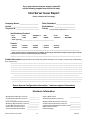
If you must contact customer support, please fill
out the following support form and have it ready.
Intel Server Issue Report
Please Complete All That Apply
Company Name: ________________________
Date Submitted: ________________________
Contact: __________________________________
Telephone #: ______________________________
Email Address: ___________________________
Priority: __________________________________
(1-Hot, 2-Critical, 3-High, 4-Low)
Intel Baseboard Product:
STL2
SCB2
SBT2
S845WD1-E
SAI2
SJP2
SDS2
SKA4
SRPL8
SRPM8
OPRF100
S815EBM1
Other (specify)__________________________________________
Chassis:
SC7000
SR4000
SC5000
SC5100
SC5150
SR1200
SR2000
SR2050
SR2100
SR2200
______________________________________________________________________________
Other (specify chassis manufacturer & part number, power supply manufacturer & part number, type & amount
of chassis fans used, fan manufacturers & part numbers)
___________________________________________________________________________________________
Problem Description (complete details of the problem setup, problem description, error message s, recreation steps, troubleshooting
steps completed, etc.)
_________________________________________________________________________________
_________________________________________________________________________________
_________________________________________________________________________________
_________________________________________________________________________________
_________________________________________________________________________________
_________________________________________________________________________________
__________________________________________________________________________
_________________________________________________________________________________
_________________________________________________________________________________
______________________________________________________________________________
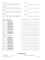
Server System Configuration Information (* indicates required information)
Hardware Information
* Main Board Part Number (PBA#/AA#)
_____________
* CPU Board Part Number (PBA#/AA#)
_____________
______________
* Front Panel Board PNumber (PBA#/AA#) _____________
* Mezzanine Board PNumber (PBA#/AA#) _____________
* System BMC Firmware Version
_______________
* System FPC Firmware Version
______________
* Power Share/Dist. Board PBA#
______________
SPD Troubleshooting Guide
-15-
* System BIOS Version
* I/O Board Part Number (PBA#/AA#)
______________
* Midplane Board Part Number (PBA#/AA#)
______________
* I/O Riser Board Part Number (PBA#/AA#)
______________
* SCSI Backplane PBA#/HSC Firmware Version _____________
* SMIC Firmware Version
______________
* Chipset Stepping
______________
04/24/02
*Processor #1_______/_______/_______/_______/_______
#2_______/_______/_______/_______/_______
S-Spec#
Speed
Stepping
*Processor
Cache size CPUID#
S-Spec#
Speed
Stepping
Cache size
S-Spec#
Speed
Stepping
Cache size
S-Spec#
Speed
Stepping
Cache size
S-Spec#
Speed
Stepping
Cache size
CPUID#
*Processor #3_______/_______/_______/_______/_______
#4_______/_______/_______/_______/_______
S-Spec#
Speed
Stepping
*Processor
Cache size CPUID#
CPUID#
*Processor #5_______/_______/_______/_______/_______
#6_______/_______/_______/_______/_______
S-Spec#
Speed
Stepping
*Processor
Cache size CPUID#
CPUID#
*Processor #7_______/_______/_______/_______/_______
#8_______/_______/_______/_______/_______
S-Spec#
Speed
Stepping
*Processor
Cache size CPUID#
CPUID#
*Memory module configuration
* Module Type (module vendor/vendor part numbers/ Intel part numbers) :
(On board or in Card 1)
J1 ___________MB (MODULE#1)
J2 ___________MB (MODULE#2)
J3 ___________MB (MODULE#3)
J4 ___________MB (MODULE#4)
J5 ___________MB (MODULE#5)
J6 ___________MB (MODULE#6)
J7 ___________MB (MODULE#7)
J8 ___________MB (MODULE#8)
J9 ___________MB (MODULE#9)
J10___________MB (MODULE#10)
J11___________MB (MODULE#11)
J12___________MB (MODULE#12)
J13___________MB (MODULE#13)
J14___________MB (MODULE#14)
J15___________MB (MODULE#15)
J16___________MB (MODULE#16)
_______________________________________________
_______________________________________________
_______________________________________________
_______________________________________________
_______________________________________________
_______________________________________________
_______________________________________________
_______________________________________________
_______________________________________________
_______________________________________________
_______________________________________________
_______________________________________________
_______________________________________________
_______________________________________________
_______________________________________________
_______________________________________________
*Memory module configuration
* Module Type (module vendor/vendor part numbers/ Intel part numbers) :
(In Card 2)
J1 ___________MB (MODULE#1)
J2 ___________MB (MODULE#2)
J3 ___________MB (MODULE#3)
J4 ___________MB (MODULE#4)
J5 ___________MB (MODULE#5)
J6 ___________MB (MODULE#6)
J7 ___________MB (MODULE#7)
J8 ___________MB (MODULE#8)
J9 ___________MB (MODULE#9)
J10___________MB (MODULE#10)
J11___________MB (MODULE#11)
J12___________MB (MODULE#12)
J13___________MB (MODULE#13)
J14___________MB (MODULE#14)
J15___________MB (MODULE#15)
J16___________MB (MODULE#16)
_______________________________________________
_______________________________________________
_______________________________________________
_______________________________________________
_______________________________________________
_______________________________________________
_______________________________________________
_______________________________________________
_______________________________________________
_______________________________________________
_______________________________________________
_______________________________________________
_______________________________________________
_______________________________________________
_______________________________________________
_______________________________________________
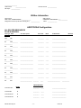
O/S Information
*Operating System
_________________________
SPD Troubleshooting Guide
-16-
*Operating System Language Version
04/24/02
__________________
*O/S Version
_______________
*MP Spec _____________
*Service Pack #
_____________
Utilities Information
*ISC Version _____________
*EMP / DPC Console Version _____________
*Diagnostics Version (Testview, PCDiag, etc.) _____________
*SSU Version _____________
*FRU/SDR Loader Version _____________
Other _____________
AGP/PCI/ISA Configuration
ALLOCATED RESOURCES
PLUG IN DEVICES
Card Type Slot#
Card Description
Driver Rev.
IRQ #
I/O Base Addr.
AGP
AGP
_____________
______________________
__________
_____
_______________________
PCI
Slot#_________
_____________
______________________
__________
_____
_______________________
PCI
Slot#_________
_____________
______________________
__________
_____
_______________________
PCI
Slot#_________
_____________
______________________
__________
_____
_______________________
PCI
Slot#_________
_____________
______________________
__________
_____
_______________________
PCI
Slot#_________
_____________
______________________
__________
_____
_______________________
PCI
Slot#_________
_____________
______________________
__________
_____
_______________________
PCI
Slot#_________
_____________
______________________
__________
_____
_______________________
PCI
Slot#_________
_____________
______________________
__________
_____
_______________________
ISA
ISA 2
_____________
______________________
__________
_____
_______________________
ISA
____________________
ISA 1
_________
_____
_____________________
FW Rev#
____________
ONBOARD DEVICE
IN USE
r
__________
_____
_______________________
*On-Board NIC
r
__________
_____
_______________________
*On-Board SCSI-1
r
__________
_____
_______________________
*On-Board SCSI-2
r
__________
_____
_______________________
*On-Board Video
SPD Problem Report
- 17 -
04/24/02
RAID
r
RAID Level: _____(0-5)
Caching Method: ____ (RB/WT)
# of Drives Used: ____________
IDE Drive Type(s): ____________________________________________________________________ (Make/Model)
SCSI Drive Type(s): ____________________________________________________________________ (Make/Model)
Other Device Type(s){CD-ROM, Tape Drive, etc.}: ____________________________________________________________________ (Make/Model)
SPD Problem Report
- 18 -
04/24/02


![Streamit Maven user manual [firmware version 2.22.0]](http://vs1.manualzilla.com/store/data/006918496_1-ec2babbff5a065a03e66471e2de505b7-150x150.png)