1
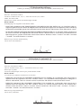
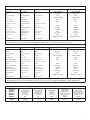
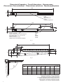
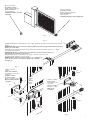
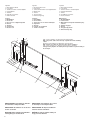
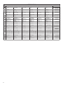
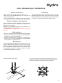
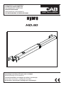
APRICANCELLO OLEODINAMICO
HYDRAULIC GATE OPERATOR
ÖLDYNAMISCHER TORÖFFNER
VÉRIN HYDRAULIQUE
ABRECANCELAS OLEODINÁMICO
OLEODYNAMICZNY OTWIERACZ BRAM
HD.80
Manuale istruzioni e catalogo ricambi
Operating instructions and spare parts catalogue
Betriebsanleitung und Ersatzteilliste
Livret d’instructions et catalogue des pièces de rechange
Manual de instrucciones y catálogo de recambios
Książeczka z instrukcjami i katalog części wymiennych
Dichiarazione CE di Conformità
Dichiarazione in accordo alle Direttive 2004/108/CE(EMC); 2006/95/CE(LVD)
Fabbricante: Automatismi CAB Srl
Indirizzo: Via della Tecnica, 10 (z.i.) - 36010 Velo d’Astico (VI) - Italia
Dichiara che il prodotto:
Attuatore oleodinamico 230Vac per cancelli a battente modello:
HD.80 - HD.80V
è conforme alle condizioni delle seguenti Direttive CE:
- DIRETTIVA 2004/108/CE DEL PARLAMENTO EUROPEO E DEL CONSIGLIO del 15 dicembre 2004 concernente il
ravvicinamento delle legislazioni degli Stati membri relative alla compatibilità elettromagnetica e che abroga la direttiva
89/336/CEE, secondo le seguenti norme armonizzate: EN 61000-6-2:2005, EN 61000-6-3:2007.
- DIRETTIVA 2006/95/CE DEL PARLAMENTO EUROPEO E DEL CONSIGLIO del 12 dicembre 2006 concernente il
ravvicinamento delle legislazioni degli Stati membri relative al materiale elettrico destinato ad essere adoperato entro
taluni limiti di tensione, secondo le seguenti norme armonizzate: EN 60335-1:2002 + A1:2004 + A11:2004 + A12:2006
+ A2:2006 + A13:2008; EN 60335-2-103:2003.
Benincà Luigi, Responsabile legale.
Velo d’Astico, 04/06/2015.
CE Declaration of Conformity
Declaration in accordance with Directives 2004/108/CE (EMC); 2006/95/CE (LVD)
The Manufacturer:Automatismi CAB Srl
Address:Via della Tecnica, 10 (z.i.) - 36010 Velo d’Astico (VI) - Italy
Declares that the product:
Hydraulic actuator 230V AC for swing gates, model:
HD.80 - HD.80V
conforms with the requirements of the following EU Directives:
- DIRECTIVE 2004/108/EC OF THE EUROPEAN PARLIAMENT AND OF THE COUNCIL of 15 December 2004, on the
harmonisation of the laws of Member States relating to electromagnetic compatibility and which cancels Directive
89/336/EEC, according to the following harmonised regulations: EN 61000-6-2:2005, EN 61000-6-3:2007.
- DIRECTIVE 2006/95/EC OF THE EUROPEAN PARLIAMENT AND OF THE COUNCIL of 12 December 2006, on the
harmonisation of the laws of Member States relating to electrical equipment designed for use with certain voltage limits,
according to the following harmonised regulations: EN 60335-1:2002 + A1:2004 + A11:2004 + A12:2006 + A2:2006 +
A13:2008; EN 60335-1-103:2003.
Benincà Luigi, Legal representative.
Velo d’Astico, 04/06/2015.
2
CE-Konformitätserklärung
Erklärung im Einklang mit den Richtlinien 2004/108/CE(EMC); 2006/95/CE(LVD)
Hersteller: Automatismi CAB Srl
Anschrift: Via della Tecnica, 10 (z.i.) - 36010 Velo d’Astico (VI) - Italien
Erklärt, dass das Produkt:
Hydraulischer 230Vac-Antrieb für Drehtoranlagen, Modell:
HD.80 - HD.80V
die Bedingungen der folgenden CE-Richtlinien erfüllt:
- RICHTLINIE 2006/95/EG DES EUROPÄISCHEN PARLAMENTS UND DES RATES vom 12. Dezember 2006 zur
Angleichung der Rechtsvorschriften der Mitgliedstaaten über die elektromagnetische Verträglichkeit und zur Aufhebung
der Richtlinie 89/336/EWG, gemäß nachstehenden harmonisierten Normen: EN 61000-6-2:2005, EN 61000-6-3:2007.
- RICHTLINIE 2006/95/EG DES EUROPÄISCHEN PARLAMENTS UND DES RATES vom 12. Dezember 2006 zur Angleichung
der Rechtsvorschriften der Mitgliedstaaten betreffend elektrische Betriebsmittel zur Verwendung innerhalb bestimmter
Spannungsgrenzen, gemäß nachstehenden harmonisierten Normen: EN 60335-1:2002 + A1:2004 + A11:2004 + A12:2006
+ A2:2006 + A13:2008; EN 60335-1-103:2003.
Benincà Luigi, Leiter der Rechtsabteilung.
Velo d’Astico, den 04/06/2015.
Déclaration de conformité CE
Déclaration en accord avec les Directives 2004/108/CE(CEM) ; 2006/95/CE(DBT)
Fabricant :Automatismi CAB Srl
Adresse :Via della Tecnica, 10 (z.i.) - 36010 Velo d’Astico (VI) - Italie
Déclare que le produit :
Actionneur oléodynamique 230 Vca pour portails battants modèle :
HD.80 - HD.80V
est conforme aux conditions des Directives CE suivantes :
- DIRECTIVE 2004/108/CE DU PARLEMENT EUROPÉEN ET DU CONSEIL du 15 dècembre 2004 concernant le
rapprochement des legislations des États membres relatives à la compatibilité électromagnétique et abrogeant la
directive 89/336/CEE, selon les suivantes normes harmonisées: EN 61000-6-2:2005, EN 61000-6-3:2007.
- DIRECTIVE 2006/95/CE DU PARLEMENT EUROPÉEN ET DU CONSEIL du 12 décembre 2006 concernant le
rapprochement des legislations des États membres relatives au materiel électrique destiné à être employé dans
certaines limites de tension ,selon les suivantes normes harmonisées: EN 60335-1:2002 + A1:2004 + A11:2004 +
A12:2006 + A2:2006 + A13:2008; EN 60335-1-103:2003.
Benincà Luigi, Responsable légal.
Velo d’Astico, 04/06/2015.
3
Declaración CE de Conformidad
Declaración según las Directivas 2004/108/CE(EMC); 2006/95/CE(LVD)
Fabricante: Automatismi CAB Srl
Dirección: Via della Tecnica, 10 (z.i.) - 36010 Velo d’Astico (VI) - Italia
Declara que el producto:
Mando oleodinámico 230Vac para portones batientes modelo:
HD.80 - HD.80V
es conforme a las condiciones de las siguientes Directivas CE:
- DIRECTIVA 2004/108/CE DEL PARLAMENTO EUROPEO Y DEL CONSEJO del 15 de diciembre de 2004 sobre la
aproximación de las legislaciones de los Estados miembros con relación a la compatibilidad electromagnética y que
abroga la Directiva 89/336(CEE, según las siguientes normas armonizadas: EN 61000-6-2:2005, EN 61000-6-3:2007.
- DIRECTIVA 2006/95/CE DEL PARLAMENTO EUROPEO Y DEL CONSEJO del 12 de diciembre de 2006 sobre la
aproximación de las legislaciones de los Estados miembros con relación al material eléctrico destinado a ser utilizado
dentro de determinados límites de tensión, según las siguientes normas armonizadas: EN 60335-1:2002 + A1:2004
+ A11:2004 + A12:2006 + A2:2006 + A13:2008; EN 60335-1-103:2003.
Benincà Luigi, Responsable legal.
Velo d’Astico, 04/06/2015.
Deklaracja zgodności CE
sporządzona zgodnie z dyrektywami europejskimi 2004/108/WE (EMC) i 2006/95/WE (LVD)
Producent: Automatismi CAB Srl
Adres: Via della Tecnica, 10 (z.i.) - 36010 Velo d’Astico (VI) - Włochy
oświadcza, że produkt:
Napęd oleodynamiczny dla bram skrzydłowyc:
HD.80 - HD.80V
- DYREKTYWY 2004/108/WE RADY PARLAMENTU EUROPEJSKIEGO z dnia 15 grudnia 2004 w sprawie zbliżania
ustawodawstwa państw członkowskich w zakresie kompatybilności elektromagnetycznej i anulującej postanowienia
Dyrektywy 89/336/EWG, zgodnie z następującymi normami zharmonizowanymi: EN 61000-6-2:2005, EN 61000-63:2007.
- DYREKTYWY 2006/95/WE RADY PARLAMENTU EUROPEJSKIEGO z dnia 12 grudnia 2006 w sprawie zbliżania
ustawodawstwa państw członkowskich w zakresie sprzętu elektrycznego przeznaczonego do użytku w ramach
wyznaczonych wartości napięcia, zgodnie z następującymi normami zharmonizowanymi: EN 60335-1:2002 + A1:2004
+ A11:2004 + A12:2006 + A2:2006 + A13:2008; EN 60335-1-103:2003.
Benincà Luigi, Upoważniony przedstawiciel prawny.
Sandrigo, 04/06/2015.
4
Tab.1
HD.80 230V
HD.80 115V
230Vac (50/60Hz)
115 Vac (50/60Hz)
1400g/min
1400 g/min
Dati tecnici
Technical data
Technische Daten
Alimentazione
Power supply
Versorgung
Motore
Motor
Motor
Corrente assorbita
Absorbed current
Stromaufnahme
Spinta
Thrust
Schub
Pressione max
Max pressure
Max. Druck
Grado di protezione
Protection rating
Schutzart
N° manovre consecutive
N° cons.ve manoeuv.
N. Vorgänge hintereinan.
Pompa
Pump
Pumpe
Diametro stelo
Ram shaft diameter
Schaftdurchmesser
Rumorosità
Noise level
Lärm
Protezione termica
Overload cut-out
Thermoschutz
150°C
150°C
Temp. funzionamento
Operating temp.
Betriebszeit
-20°C/+50°C
-20°C/+50°C
Condensatore
Condenser
Kondensator
10 µF
36 µF
Olio
Oil
Öl
BIO OIL 3.5 l (3 kg)
BIO OIL 3.5 l (3 kg)
Tipologia blocco
Type of lock
Verrieglungstyp
**
**
1,3 A
2,6 A
10000 N (~1000Kg)
10000 N (~1000Kg)
50 bar
50 bar
IP 55
IP 55
*
*
a lobi
a lobi
Ø 22 mm
Ø 22mm
< 70 dB (a)
< 70 dB (a)
* Uso intensivo - Intense use - Intensive Nutzung
** Reversibile (Richiede elettroserratura) - Reversible (Requires electric lock) - Reversibel (Erfordert Elektroverriegelung)
Données technique
Datos técnicos
Dane techniczne
Alimentation
Alimentación
Zasilanie
Moteur
Motor
Silnik
Courant absorbé
Corriente absorbida
Zużycie prądu
Poussée
Empuje
Pchnięcie
Pression max.
Presión máx
Ciśnienie max
Indice de protection
Grado de protección
Stopień ochrony
Nb de manœuv. conséc.
N° maniob. consecut.
N° kolejnych manewrów
Pompe
Bomba
Pompa
Diamètre tige piston
Diámetro del vástago
średnica trzpienia
Niveau sonore
Nivel de ruido
Hałaśliwość
Protection thermique
Protección térmica
Ochrona termiczna
Temp. fonctionnement
Temp. de funcion.
Temp. działania
Condensateur
Condensador
Kondensator
Huile
Aceite
Olej
Type de blocage
Tipología de bloqueo
Rodzaj blokady
HD.80 230V
HD.80 115V
230Vac (50/60Hz)
115 Vac (50/60Hz)
1400g/min
1400 g/min
1,3 A
2,6 A
10000 N (~1000Kg)
10000 N (~1000Kg)
50 bar
50 bar
IP 55
IP 55
*
*
a lobi
a lobi
Ø 22 mm
Ø 22mm
< 70 dB (a)
< 70 dB (a)
150°C
150°C
-20°C/+50°C
-20°C/+50°C
10 µF
36 µF
BIO OIL 3.5 l (3 kg)
BIO OIL 3.5 l (3 kg)
**
**
* Usage intensif - Uso intensivo - Użytkowanie intensywne
** Réversible (Nécessite une serrure électrique) - Reversible (Pedir electrocerradura) - Odwracalny (Wymaga zamka elektrycznego)
Tab.2 - Scelta del modello - Model sizing - Wahl des Modells -Choix du modèle - Elección de modelo - Wybór modelu
MODELLO
MODEL
MODELLS
MODÈLE
MODELO
MODELU
Peso max anta
Door leaf weight
Türflügelgewicht
Poids porte
Peso hoja
Ciężar skrzydła
Lunghezza max anta
Door leaf width
Flügellänge
Longueur porte
Longitud hoja
Dł. skrzydła
Corsa utile
Stroke length
Nutzhub
Corsa utile
Carrera útil
Posuw korzystny
(kg)
(m)
(mm)
HD.80
1000
8
390
Portata pompa
Pump delivery
Pumpenleistung
Débit pompe
Caudal de la bomba
Natężenie przepływu
pompy
(l/min)
0,75
Velocità stelo
Ram speed
Schaftgeschwindigkeit
Vitesse tige piston
Velocidad del vástago
Prędkość trzpienia
(cm/s)
0,75
5
Dimensioni d’ingombro - Overall dimensions - Abmessungen
Dimensions d’encombrement - Dimensiones exteriores - Wymiary gabarytowe
1436
107
Mettere a livello.
Level.
Nivellieren.
Mettre de niveau.
Nivelar.
Ustawić na wysokości
1350
P
S
390
135
98
Corsa utile.
Stroke.
Hub.
Course.
Carrera.
Posuw.
Interasse ancoraggi.
Distance between axes of anchoring bolts.
Die maximale Öffnung der Verankerungen.
Entraxe ancrages.
Distancia entre ejes ancrajes.
Współośowość elementów mocujących.
Fig. 1
1350
B
C
A
Z
D
Fig. 2
α
HD.80
α
A (mm)
90°
100°
110°
120°
195
180
165
140
B (mm) C (mm) D (mm)
195
180
175
175
130
115
100
65
65
65
65
65
Z (mm)
T*(s)
HD.80
Corsa./ Stroke.
Hub./ Course.
Carrera./ Posuw
(mm)
100
100
100
100
50
50
50
49
390
390
390
383
*Tempo apertura indicativo, escluso rallentamento
*Indicative opening time, excluded slowdown
*Hinweisende öffnungszeit, ausschließliches Verlangsamen
*Temps indicatif d’ouverture, ralentissement exclu
*Tiempo indicativo de abiertura, deceleración excluido
*Wskazujący czas otwierania, wyłączył zwalniają
6
Arresto in apertura.
Stop when opening.
Endanschlag zur Öffnung.
Arrêt en ouverture.
Tope en apertura.
Chwytak blokujący podczas
otwierania.
Arresto in chiusura.
Stop when closing.
Endanschlag zur Schließung.
Arrêt en fermeture.
Tope de cierre.
Chwytak blokujący podczas zamykania.
Fig. 3
Fig. 4
S
10
m
m
IMPORTANTE! Estrarre completamente lo stelo e farlo rietrare di circa 10mm prima di fissare la staffa “S”
all'anta.
IMPORTANT! Slide out the ram shaft completely and then back in by approx. 10mm before fastening
bracket “S” to the wing.
WICHTIG! Den Schaft ganz ausziehen und um zirka 10 mm wieder einschieben, bevor der „S“-Bügel
am Torflügel befestigt wird.
IMPORTANT! Extraire complètement la tige du piston et la faire rentrer d’environ 10
mm avant de fixer la patte «S» au vantail.
¡IMPORTANTE! Extraer completamente el vástago y volverlo a meter unos 10
mm antes de fijar el estribo “S” en la cancela.
WAŻNE! Wyjąć całkowicie trzpień i wpuścić go na głębokość
około 10 mm jeszcze przed zamocowaniem do skrzydła
zaczepu „S”.
Fig. 5
Tagliare a misura e
saldare
Cut to size and weld
Auf Maß zuschneiden und
schweißen
Couper à la bonne
mesure et souder
Cortar a medida y soldar
Wyciąć według rozmiaru
i zespawać
V
P
P
S
Grasso
Grease
Fett
Graisse
Grasa
Smar
Avvitare o saldare.
Bolt or weld.
Einschrauben oder
schweißen.
Visser ou souder
Atornillar o soldar.
Wkręcić lub
zespawać.
R
D
D
Rs
F
Vs
Fig. 6
7
6
Regolazione forza di spinta
Adjustment of the thrust
Einstellung der Schubkraft
Réglage force de poussée
Regulación de la fuerza de empuje
Regulacja siły popychu
6
6
Fig. 7
CLOSE
Fig. 8
OPEN
Nel caso la manovra manuale risultasse difficoltosa ruotare la vite evidenziata in direzione + (massimo un
giro). Prima di tornare al funzionamento automatico riportarla alla posizione originale (-).
In case the manual operation proves difficult, rotate the highlighted screw toward the + (maximum one
rotation). Before to go back to the automatic functioning bring the screw to the original position (-).
Fig. 9
Livello Olio
Oil level
Der Ölstand darf
Niveau d’huile
Nivel de aceite
Poziom oleju
Verificare che con stelo completamente rientrato, il livello dell'olio raggiunga la sede evidenziata (circa 1mm),
nel caso effettuare un rabbocco utilizzando esclusivamente BIO.OIL.
Verify that when the stem is totally inside, the oil level reaches the indicated position (about 1 mm), otherwise do a refill by using exclusively HYDRO OIL.
Fig. 10
Regolazione rallentamento in chiusura
Adjustment of the slowdown in closing
Einstellung der Verlangsamung beim Schließen
Réglage ralentissement en fermeture
Regulación de la deceleración en el cierre
Regulacja zwalniania w zamykaniu
3
Fig. 11
8
Anta sinistra
Left-hand wing
Linker Flügel
Vantail gauche
Hoja izquierda
Skrzydło lewe
Anta destra
Right-hand
wing
Rechter Flügel
Vantail droit
Hoja derecha
Skrzydło prawe
Foro di scarico sempre rivolto a terra
Drain hole faces the ground
Die Auslassöffnung muss
immer zum Boden zeigen
Trou de drainage toujours
tourné vers le sol
Orificio de descarga siempre
orientado hacia el suelo
Należy uważać na otwór spustowy
który powinien być zawsze skierowany do ziemi.
Fig. 12
Collegamenti - Connections - Kabelanschlüsse
Connexions - Conexiones - Podłączenia
Marrone= marcia motore e condensatore.
Brown= motor gear and capacitor.
Braun= Motorgang und Kondensator.
Marron= marche moteur et condensateur.
Marrón= marcha motor y condensador.
Brązowy = bieg silnika i praca kondensatora
Grigio = comune.
Grey = common.
Grau = gemeinsamer Leiter.
Gris = commun.
Gris = común.
Szary = wspólny.
Guaina spiralata ø12
ø12 spiral sheath
Spiralmantel ø12
Gaine spiralée ø12
Vaina corrugada ø12
Osłona spiralna ø12
GND
Nero= marcia motore e condensatore.
Black= motor gear and capacitor.
Schwarz= Motorgang und Kondensator.
Noir= marche moteur et condensateur.
Negro= marcha motor y condensador.
Czarny = bieg silnika i praca kondensatora
9
Legenda:
1 Motoriduttore HD.80
2 Fotocellule
3 Selettore a chiave o tastiera digitale
4 Lampeggiante
5 Antenna
6 Centrale di comando.
7 Elettroserratura
Legende:
1 HD.80-Getriebemotor
2 Photozellen
3 Schlüsselwahlschalter oder Digitaltastatur
4 Blinkleuchte
5 Antenne
6 Steuerzentrale.
7 Elektroverriegelung
Leyenda:
1 Motorreductor HD.80
2 Fotocélulas
3 Selector de llave o teclado digital
4 Lámpara destellante
5 Antena
6 Centralita de comando.
7 Electrocerradura
Legend:
1 HD.80 Motor
2 Photocells
3 Key selector or digital keyboard
4 Beacon
5 Antenna
6 Control unit.
7 Electric lock
Légende:
1 Vérin HD.80
2 Photocellules
3 Sélecteur à clé ou clavier numérique
4 Clignotant
5 Antenne
6 Logique de commande.
7 Serrure électrique
Objaśnienia:
1 Siłownik HD.80
2 Fotokomórki
3 Wybierak kluczowy lub klawiatura przyciskowa
4 Światło migające
5 Antena
6 Stacyjka napędowa.
7 Zamek elektryczny
5
3
N.B.: Tenere separati i cavi di potenza da quelli ausiliari.
N.B.: The power cables must be kept separated from the auxiliary
cables.
Wichtig: Leistungskabel von Hilfskabeln getrennt halten.
N.B.: Séparer les câbles de puissance des câbles auxiliaires.
N.B.: Tener separados los cables de potencia de los auxiliares.
Uwaga: należy trzymać w oddali przewody zasilania od przewodów pomocniczych.
2x1,5
2x1
RG 58
4
1
2x
1,5
4x
2
1
7
1,5
1
4x
1
4x
2
n
mi
1,5 ac
V
0
23
3x
IMPORTANTE:L'installazione dell'elettroserratura è indispensabile.
IMPORTANT: l’installation de la serrure électrique est indispensable.
IMPORTANT: Installation of an electric
lock is essential.
IMPORTANTE: Es imprescindible instalar la electrocerradura.
WICHTIG: Die Installation der Elektroverriegelung ist unerlässlich.
WAŻNE: Instalacja zamka elektrycznego jest nieodzowna.
10
6
Attenzione
• Prima di procedere all’installazione leggere le istruzioni qui riportate.
• È fatto divieto assoluto di utilizzare il prodotto HYDRO per applicazioni diverse da quelle contemplate dalle presenti
istruzioni.
• Istruire l’utilizzatore all’uso dell’impianto.
• Consegnare all’utilizzatore le istruzioni ad esso rivolte.
• Tutti i prodotti CAB sono coperti da polizza assicurativa che risponde di eventuali danni a cose o persone causati da
difetti di fabbricazione, richiede però la marcatura CE della “macchina” e l’utilizzo di componenti originali CAB.
Notizie generali
Attuatore oleodinamico per cancelli a battente, disponibile in varie versioni:
HD.80 230V versione 230 Vac - reversibile - richiede elettroserratura
HD.80 115V versione 115 Vac - reversibile - richiede elettroserratura
Tutti i modelli sono dotati di funzione di rallentamento idraulico regolabile in fase di chiusura e di rallentamento fisso in
apertura. E' necessario utilizzare pertanto tutta la corsa, rispettando le quote di installazione indicate.
Verifiche preliminari
Per un buon funzionamento delle automazioni in oggetto, il cancello da automatizzare dovrà rispondere alle seguenti
caratteristiche:
- buona robustezza e rigidità.
- le cerniere devono presentare giochi minimi e permettere che le manovre manuali siano dolci e regolari.
- in posizione di chiusura le ante devono combaciare fra loro per tutta l’altezza.
Arresti meccanici
Nel caso non siano già presenti, è necessario predisporre degli arresti meccanici in chiusura ed apertura (Fig.3), indipendentemente dal tipo di attuatore installato.
L'arresto meccanico in chiusura, in particolare, è indispensabile date le caratteristiche peculiari degli attuatori oleodinamici.
Messa in posa dell’automatismo
1 Stabilire l’altezza dal suolo dell’automatismo (si consiglia il più centrato possibile rispetto all'anta ed in corrispondenza
di un solido traverso).
Tenere presente che sul fondo dell'attuatore è presente un foro di sfiato che, in particolari condizioni, potrebbe aspirare
dei liquidi (pioggia/neve) all'interno dell'automazione. Per questo motivo è sconsigliata una posizione di installazione
in prossimità del suolo.
2 Saldare o fissare la piastra P facendo riferimento alle quote di installazione (Fig.2) e allo schema di montaggio (Fig.5/6):
- inserire il perno P sulla staffa P come in figura
- inserire nella staffa P la forcella F del motore HD.80
- fissare il tutto con la rondella R ed il dado autobloccante D
- rimuovere la vite di chiusura sfiato VS con la sua guarnizione RS. (vedi nota “Vite di sfiato”)
Rispettare le quote indicate nelle tabelle di fig. 2, modificando in caso di necessità la lunghezza della piastra. In alcuni
casi può essere necessario ricavare una nicchia nel pilastro.
Il rispetto delle quote di installazione è indispensabile per il buon funzionamento dell'attuatore.
In riferimento alle tabelle di installazione tenere presente che:
Per aperture dell'anta a 90°: A+B deve essere uguale alla corsa dell'attuatore
Per aperture dell'anta maggiori di 90°:
A+B deve essere inferiore alla corsa dell'attuatore.
Mantere la differenza delle quote entro 40mm. Differenze superiori rendono irregolare il movimento dell'anta. Al diminuire delle quote A e B aumenta la velocità dell'anta.
Rispettare le normative vigenti.
3 Estrarre completamente lo stelo e farlo rientrare di circa 10 mm.
E' importate lasciare una extra-corsa di sicurezza di 10 mm, sia in chiusura, sia in apertura. La corsa utile indicata
nei dati tecnici e nelle tabelle di installazione è già decurtata di questi 20 mm.
4 Mantenendo perfettamente orizzontale l'attuatore, individuare il punto di fissaggio della staffa sull'anta.
Saldare o avvitare provvisoriamente la staffa come indicato in Fig.6.
5 Sbloccare l'attuatore e verificare manualmente che l'anta sia libera di aprirsi completamente fermandosi sugli arresti
meccanici di finecorsa e che il movimento dell’anta sia regolare e privo di attriti.
6 Fissare definitivamente la staffa.
NOTA: VITE DI SFIATO.
A fianco del foro di sfiato è presente un foro cieco dove avvitare la vite e la guarnizione per utilizzi futuri.
Appena viene rimossa la vite e durante le prime manovre dell'automazione è possibile si verifichi una piccola fuoriuscita
di olio. Ciò è normale e non comporta anomalie di funzionamento.
11
Manovra manuale e d’emergenza
I motoriduttori HD.80, essendo reversibili richiedono semplicemente lo sgancio dell'elettroserratura, dopodiché l'anta
può essere manovrata manualmente.
Spingere con moderazione l'anta alla sua estremità, accompagnandola per tutta la corsa.
La manovra può essere agevolata allentando la valvola di sblocco (Fig.9).
Regolazione forza di spinta
L'attuatore è provvisto di un dispositivo antischiacciamento (valvole by-pass) per la limitazione della forza di spinta
sull'anta in presenza di ostacolo. Una volta rimosso l'ostacolo l'anta prosegue la sua corsa per il tempo di lavoro impostato dalla centrale di comando.
• Aprire lo sportellino di protezione (Fig.7), quindi utilizzando una chiave a barra esagonale da 6 mm procedere alla
regolazione della forza (Fig.8).
• Sono presenti due valvole regolabili una regola la spinta in fase di apertura (Open), l'altra regola la forza in fase di
chiusura (Close).
• Rotando la valvola in direzione + si aumenta la forza di spinta dell'anta viceversa (direzione - ) la forza diminuisce.
ATTENZIONE! Questa regolazione influisce sul grado di sicurezza dell’automazione.
Verificare che la forza applicata sull’anta sia conforme con quanto previsto dalle normative vigenti.
Regolazione rallentamento
Tutti i modelli sono provvisti di rallentamento in fase di apertura e chiusura, per un movimento più lento dell'anta durante
gli ultimi secondi di manovra.
Entrambi i rallentamenti avvengono nell'ultima fase di corsa dello stelo, è pertanto importante utilizzare tutta la corsa
rispettando le quote di installazione indicate.
Il rallentamento in chiusura può inoltre essere regolato mediante l'apposita valvola (Fig.11).
Rimuovere il tappo di protezione e utilizzando una chiave a barra esagonale da 3mm:
- allentare (rotazione antioraria) la valvola per incrementare la velocità di rallentamento.
- fissare (rotazione oraria) la valvola per ridurre la velocità di rallentamento.
Allentando al massimo la valvola si disattiva la funzione di rallentamento.
Non forzare mai la valvola di regolazione.
Posizionamento delle coperture
Una volta effettuata la regolazione del rallentamento è possibile riposizionare le coperture (Fig.12).
Prestare attenzione al foro di scarico che deve essere sempre rivolto verso terra.
Collegamenti
L'attuatore viene fornito con cavo di collegamento già inserito e collegato (Fig.12). Per il collegamento alla centrale di
comando, fare riferimento alla schema e alle istruzioni della centrale di comando.
Per proteggere il cavo di alimentazione si consiglia l'utilizzo di una guaina spiralata da 12mm da inserire nell'apposito
raccordo.
E' obbligatorio effettuare il collegamento di messa a terra.
Rabbocco/sostituzione olio
Tutti gli operatori oleodinamici richiedono una verifica periodica del livello dell'olio.
Per il rabbocco è sufficiente, dopo aver tolto alimentazione di rete all'impianto, rimuovere le 4 viti che fissano la copertura (Fig.7).
Il livello dell'olio, a stelo completamente rientrato (anta aperta), deve raggiugere la nicchia evidenziata in fig. 10. Utilizzare esclusivamente olio BIO OIL.
12
Important
• Before installing the operator read these instructions.
• Use of a HYDRO product for any application not described in this instruction manual is prohibited.
• The user must be instructed on the use of the automation system.
• The user must be consigned the instruction manual.
• All CAB products are insured against damage or injury caused by manufacturing defects under the essential condition that the operator has the CE marking and all genuine CAB components are installed.
General Information
Hydraulic operator suitable for swinging gates, available in two different versions.
HD.80 230V 230V version-reversible- electric lock is needed
HD.80 115V 115V version-reversible- electric lock is needed
All the versions are provided with hydraulic slow down adjustable during closing phase and fixed during opening phase.
It is necessary to use the whole stroke, complying with the specified installation geometry.
Preliminary Checks
For the gate automation to work properly, the actual gate must have the following characteristics:
- it must be robust and rigid.
- the hinges must have only limited play and provide smooth and gentle gate movements.
- the whole height of the wings must be in contact when closed.
Gate Stops
If they are not already provided, install gate stops on the opening and closing stroke limits (Fig.3) regardless of the type
of operator being installed.
The mechanical stop in close position is compulsory because of the particular characteristics of the hydraulic actuators.
Installing the automation system
1 Establish the height of the automation from the ground (preferably as close to the centre of the wing as possible and
along a solid cross rail).
Remember that under the operator there is a vent hole and in certain conditions (e.g. rain or snow) it may draw liquid
into the automation. For this reason it is best not to install the operator too close to the ground.
2 Weld or otherwise anchor plate P in place, see installation distances (Fig.2) and the installation diagram (Fig.5):
- insert pin P in bracket P as in the figure
- insert the fork F of the HD.80 into the bracket P
- lock everything in place by washer R and self-locking nut D
- remove the vent plug VS with its gasket RS. (see note “Vent plug”)
Observe the distances given in the tables at fig. 2, correcting the length of the plate if necessary. In some cases a
recess may have to be made in the post.
It is essential that the installation distances are respected for the operator to work correctly.
With reference to the installation tables note that:
For the wing to open 90°: A+B must be equal to the operator stroke
For the wing to open more than 90°:
A+B must be less than the operator stroke.
Keep the length differences within 40mm. Over this difference the wing movement becomes uneven. When reducing
lengths A and B , increase the wing speed.
Comply with all statutory regulations.
3 Slide out the ram shaft completely and then slide back in by approx. 10 mm. Lock the operator in place.
Always leave a safety overrun of 10 mm in both the closing and opening strokes. The stroke length given in the technical data and installation tables has already been reduced by the necessary 20 mm.
4 Make sure the operator is kept perfectly level and mark the point where the bracket will be attached to on the wing.
Temporarily weld or bolt the bracket in place as shown in Fig.6.
5 Release the operator and swing the gate by hand to check it moves freely to fully open and stops on the gate stop.
The wing must move smoothly and evenly.
6 Anchor the bracket permanently.
NOTE: VENT PLUG.
Next to the vent a dead hole has been provided where the plug and gasket can be kept for future use.
On removing the plug and during the first operator manoeuvres a small quantity of oil may leak out. This is perfectly
normal and should not be considered a fault.
13
Manual and emergency gate operation
Being reversible, the motors HD.80 can be released simply by unlocking the electric lock, after that the leaf can be
operated manually.
Slowly push the wing by its outer end, accompanying it all the way to the gate stop.
The operation can be made easier by loosening the release valve (Fig.9).
Adjusting the thrust
The operator is equipped with anti-squash by-pass valve that limit the thrust on the wing when it meets an obstacle.
Once the obstacle is removed the wing will continue its stroke for the work time set by the control unit.
• Open the protective cover (Fig.7) and use a 6 mm hexagonal key to adjust the thrust (Fig.9).
• There are two adjustable valves, one governs the opening thrust (Open), the other governs the closing thrust
(Close).
• Turn the valve towards + to increase the thrust on the wing and vice-versa (i.e. towards - ) to reduce the thrust.
CAUTION! This adjustment is directly linked to the safety level of the automation.
Make sure that the thrust applied on the wing complies with statutory regulations.
Slow down adjustement
all the versions are provided with slow down in close and open position for a slower movement during the last seconds
of the maneuver.
ìThe slow down in both direction starts in the last part of the stroke, so it is very important to use the whole stroke and
respect the indicated installation geometry.
ìThe slow down in close position can be adjusted by means of the dedicated valve (Fig.11).
ìRemove the protection cap and using an allen key by 3 mm:
ì-loosen ( counterclockwise rotation) the valve in order to increase the slow down speed
ì-tighten (clockwise rotation) the valve in order to reduce the slow down speed.
Never force the adjusting valve
The protective covers
After adjusting the slowdown the covers can be replaced (Fig.11).
Take great care in ensuring that the drain hole faces the ground.
Wiring
The operator is supplied with the wiring cable already installed and wired (Fig.12). To connect it to the control unit see
the diagram and instructions for the control unit.
The power cable is best protected by a 12mm spiral sheath that has to be inserted in the coupling provided.
An earth connection is compulsory.
Topping up/changing oil
The oil level in all hydraulic operators must be periodically checked.
To top up the oil first shut-off the mains power to the system and then remove the 4 screws on the terminal block, which
also acts as oil cap.
The oil level, when the stem is totally inside (open leaf) must reach the cavity showed in fig.10
Only use BIO OIL.
14
16
17
3
2
1
8
7
10
6
9
5
4
12
11
13
15
14
23
HYDRO HD.80
N°
Cod.
1
End plåate
Bodenscheibe
Fond
Fondo
Spód
C4395003
2
Serbatoio
Tank
Tank
Réservoir
Depósito
Zbiornik
C5667021
3
Tappo
End cap
Deckel
Bouchon
Tapón
Zatyczka
C5837076
Motore 230V
Motor 230V
Motor 230V
Moteur 230V
Motor 230V
Silnik 230V
C3587072
Motore 115V
Motor 115V
Motor 115V
Moteur 115V
Motor 115V
Silnik 115V
C3587075
5
Pompa
Pump
Pumpe
Pompe
Bomba
Pompa
6
Distributore
Distributor
Verteiler
Distributeur
Distribuidor
Dystrybutor
C3396221
7
Testa rallentam.
OPEN
Slowdown head
OPEN
Kopf Verlangs.
OPEN
Tête ralentiss.
OPEN
Cabeza decel.
OPEN
Przód zwalniania
OPEN
C4396203
8
Testa rallentam.
CLOSE
Slowdown head
CLOSE
Kopf Verlangs.
CLOSE
Tête ralentiss.
CLOSE
Cabeza decel.
CLOSE
Przód zwalniania
CLOSE
C3396220
9
Stelo
Ram shaft
Schaft
Tige piston
Vástago
Trzpień
C3633006
10
Testa snodo
Pivot head
Gelenkkopf
Tête articul.
Cabeza articul.
Przód przegubu
CF8780020
11
Tubo
Barrel
Rohrleitung
Tube
Tubo
Rura
CF8868010
12
Copristelo
Ram sleeve
Schaftdeckel
Carter piston
Cubrevástago
Osłona trzpienia
13
Cavo alimentaz.
Power cable
Stromkabel.
Câble alim.
Cable alimen.
Przewód zasilania
CF8171160
Condensatore 10µF
Capacitor 10µF
Kondensator 10µF
Condensateur 10µF
Condensador 10µF
Kondensator 10µF
CF8234078
Condensatore 36µF
Capacitor 36µF
Kondensator 36µF
Condensateur 36µF
Condensador 36µF
Kondensator 36µF
CF8234077
15
BIO Oil (2 L)
BIO Oil (2 L)
BIO Oil (2 L)
BIO Oil (2 L)
BIO Oil (2 L)
BIO Oil (2 L)
16
Blister
Blister
Blister
Blister
Blister
Blister
17
Kit Guarnizioni
Seals kit
Kit Dichtung
Garniture Set
Set Juntas
Uszczelka
4
14
24
Denominazione - Description - Bezeichnung - Dénomination - Denominación - Określenie
Fondello
CF8634001
C5868011
9603002
C4089208
9688249
Libro istruzioni per l’utilizzatore
Hydro
Norme di sicurezza
Attenzione
•Non sostare nella zona di movimento delle ante.
•Non lasciare che i bambini giochino con i comandi o in
prossimità delle ante.
•In caso di anomalie di funzionamento non tentare di
riparare il guasto ma avvertire un tecnico specializzato.
Tutti i prodotti CAB sono coperti da polizza assicurativa che
risponde di eventuali danni a cose o persone causati da
difetti di fabbricazione, richiede però la marcatura CE della
”macchina” e l’utilizzo di componenti originali CAB.
Manovra manuale e d’emergenza
HD.80, essendo reversibili richiedono semplicemente lo
sgancio dell'elettroserratura, dopodichè l'anta può essere
manovrata manualmente.
Spingere con moderazione l'anta alla sua estremità, accompagnandola per tutta la corsa.
La manovra può essere agevolata allentando la valvola di
sblocco.
Manutenzione
• Astenersi assolutamente dal tentativo di effettuare riparazioni, potreste incorrere in incidenti; per queste operazioni
contattare un tecnico specializzato.
• Verificare periodicamente l’efficienza dei dispositivi di
sicurezza e le altre parti dell’impianto che potrebbero
creare pericoli in seguito ad usura.
Smaltimento
Qualora il prodotto venga posto fuori servizio, è necessario
seguire le disposizioni legislative in vigore al momento per
quanto riguarda lo smaltimento differenziato ed il riciclaggio
dei vari componenti (metalli, plastiche, cavi elettrici, ecc.);
è consigliabile contattare il vostro installatore o una ditta
specializzata ed abilitata allo scopo.
Aprire lo sportellino di protezione
Nel caso la manovra manuale risultasse difficoltosa ruotare la vite
evidenziata in direzione + (massimo un giro). Prima di tornare al funzionamento automatico riportarla alla posizione originale (-).
6
6
25
Hydro
User’s handbook
Safety rules
Waste disposal
• Do not stand in the movement area of the gate.
• Do not let children play with controls and near the gate.
• Should operating faults occur, do not attempt to repair
the fault but call a qualified technician.
If the product must be dismantled, it must be disposed according to regulations in force regarding the differentiated
waste disposal and the recycling of components (metals,
plastics, electric cables, etc..). For this operation it is advisable to call your installer or a specialised company.
Manual and emergency gate operation
Being reversible, the motors HD.80 can be released simply
by unlocking the electric lock, after that the leaf can be
operated manually.
Slowly push the wing by its outer end, accompanying it all
the way to the gate stop.
The operation can be made easier by loosening the release
valve.
Warning
All CAB products are covered by insurance policy for any
possible damages to objects and persons caused by construction faults under condition that the entire system be
marked CE and only CAB parts be used.
Maintenance
• It is mandatory not to carry out extraordinary maintenance
or repairs as accidents may be caused. These operations must be carried out by qualified personnel only.
• Periodically check safety components and any other parts
of the system that may become hazardous if worn.
Open the protective cover
In case the manual operation proves difficult, rotate the highlighted
screw toward the + (maximum one rotation). Before to go back to the
automatic functioning bring the screw to the original position.
6
6
26
CL8542201 05/2015 Rev.0
AUTOMATISMI CAB Srl - Via della Tecnica,10 (z.i.) - 36010 Velo d’Astico (VI) (Italia) - Tel. 0445 741215 - Fax 0445 742094