1
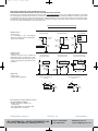
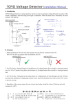
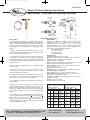
E-26:E-26
7/30/10
3:16 PM
Page 1
Bulletin E-26
Model V10 Flotect® Mini-Size Flow Switch
Specifications – Installation and Operating Instructions
INSTALLATION
1. Carefully unpack switch and remove any packing material from lower
housing. Trim the vane at the appropriate mark for the size of pipe being
used. See actuation/deactuation chart. CAUTION: Mechanical shock or
vibration can cause permanent damage to the reed switch. Take care to
avoid dropping the unit on hard surfaces or impacting the switch
assembly.
2. Apple pipe thread sealant tape or pipe thread sealant to the 1/2˝ male
NPT mounting threads and install switch in the system piping with the
arrow on side pointing in the direction of flow.
3. Connect wiring in accordance with local electrical codes. NOTE: the
/8˝ NPT fitting is not a conduit connection and any loading on this fitting
can adversely affect switch operation. Also, any rigid connection to this
fitting will prevent adjustment of switching action between normally open
and normally closed.
1
4. Inductive, capacitive and lamp loads can all create conditions harmful
to the reed switch.
A) Inductive loads can be caused by electromagnetic relays,
electromagnetic solenoids and electromagnetic counters, all with
inductive components as the circuit load.
B) Capacitive loads can be caused by capacitors connected in series
with or parallel to the reed switch. In a closed circuit the cable length
(150 ft. or more) to the switch can introduce a capacitance.
C) Lamp loads can be caused by switching lamp filaments which have
low cold resistance.
In addition to these causes, exceeding any of the maximum electrical
ratings can lead to premature or immediate failure. This includes inrush
and surge currents greater than the maximum switching current. Use
caution when evaluating system loads and current. To accommodate
these conditions, see diagrams on the reverse which depict possible
solutions.
5. After installation, set the switch action to NO (normally open) or NC
(normally closed). Normally closed contacts open and normally open
contacts close when increasing flow actuates the reed switch. To
change, loosen, but do not remove, the two screws on the top cap. Slide
the reed switch assembly to expose the switch action selected. Tighten
screws when adjustment is complete.
W.E. ANDERSON DIV., DWYER INSTRUMENTS, INC.
P.O. BOX 358 • MICHIGAN CITY, INDIANA 46361 U.S.A.
MAINTENANCE
Following final installation of the Model V10 Flow Switch, no routine
maintenance is required. A periodic check to confirm proper
actuation/deactuation is recommended. These units are not field
repairable and switches in need of service should be returned, freight
prepaid, to the address below. Please include an explanation of the
problem plus any available application information.
W.E. Anderson Division,
Dwyer Instruments, Inc.
250 Highgrove Road
Grandview, MO 64030
PHYSICAL DATA
Temperature Limit: 200°F (93°C) maximum.
Operating Pressure: Brass body - 1000 psig (69 bar) maximum.
Stainless steel body - 2000 psig (138 bar) maximum.
Piping Connection: 1/2˝ male NPT.
Switch: Hermetically sealed single pole, single throw reed switch. Field
adjustable between normally open and normally closed.
Electrical Ratings: 1.5A @ 24 VDC resistive, 0.001A @ 200 VDC
resistive, 0.5A @ 120 VAC.
Wire: 22 AWGx18 inches (460 mm) long.
Switch Body: Choice of standard brass or optional 303 stainless steel.
Reed Switch Housing: Polypropylene.
Vane: 301 stainless steel, 7/16˝ wide x.020˝ thick (11x.51 mm).
Wetted Materials: 301, 302 and 316 stainless steel, ceramic 8 magnet,
brass or optional 303 stainless steel body.
Installation: Install with index arrow pointing in direction of flow. Can be
mounted in any position.
Weight: 41/2 ounces (128 grams).
Overall Length: 5.25 inches (133 mm).
Cold Water Flow Rates
Approximate actuation/deactuation
GPM upper, LPM lower
N.C.
Pipe Trim N.O.
L
2.6/2.3
2.6/2.5
1/2˝
9.8/8.7
9.8/9.5
J
3.1/2.7
3.1/2.8
3/4˝
11.7/10.2 11.7/10.6
H
4.8/4.5
4.8/4.4
1˝
18.2/17
18.2/16.7
6.2/5.6
6.1/5.6
1-1/4˝ E
23.5/21.2 23.1/21.2
8.2/7.7
8.2/7.7
1-1/2˝ C
31/29.1
31/29.1
Full 9.5/9.1
9.5/9
2˝
36/34.4
36/34.1
Phone: 219/879-8000
Fax: 219/872-9057
Air Flow Rates
Approximate actuation/deactuation
SCFM upper, LPM lower
N.C.
Pipe Trim N.O.
10.3/8.8
10.2/9.2
1/2˝ L
291.7/250 288/260
13/11.6
12.9/11.6
3/4˝ J
368.3/328 365/328
19.2/17.6 18.9/17.6
1˝
H
543.3/498 535/498
24.8/22.2 24.5/22.5
1-1/4˝ E
701.7/628 693/637
33.4/31.2 33/30.6
1-1/2˝ C
946.7/883 935/867
2˝
Full 50.2/48.4 50.2/47.7
1422/1370 1422/1352
www.dwyer-inst.com
e-mail: [email protected]
E-26:E-26
7/30/10
3:16 PM
Page 2
REED SWITCH PROTECTION CIRCUIT INFORMATION BULLETIN
READ INFORMATION BELOW BEFORE INSTALLING YOUR NEW REED SWITCH CONTROL!
Exceeding the current capacity of this Reed Switch control may cause FAULTY OPERATION! Be aware of the inductive and capacitive or lamp loads
you may be placing on you Reed Switch Control. The circuits below outline possible solutions to preventing overloads due to inrush or surge currents
exceeding maximum or when the switch current and product of the inductive back EMF exceed the switch’s power rating. Also the circuit for prevention
of overload when switching filament lamps (low “cold” resistance) is outlined below. Failure to follow these measures to protect Reed Switch Contacts
may cause the contacts to weld together or result in premature wear.
Possible Circuit Solutions Indicated by Dashed Lines
Inductive Loads
Possible causes –
An electromagnetic relay, electromagnetic
solenoid, electromagnetic counter with inductive
component as circuit load.
RC SUPPRESSION
VARISTER PROTECTION
DIODE SUPPRESSION
2
C
INDUCTIVE
LOAD
DIODE
INDUCTIVE
LOAD
INDUCTIVE
LOAD
R
VARISTER
SWITCH
10
[uf]
10*I (1+50/E)
R
PIV DIODE > V
Capacitive Loads
Possible causes –
A capacitor connected in series or parallel with
Reed Switch control. In a closed circuit, a cable
length (usually greater than 50m [162.5 ft.]) used
to connect reed switch may also introduce static
capacitance.
REED
SWITCH
REED
SWITCH
REED
SWITCH
USED IN
AC CIRCUITS
SWITCH
RESISTOR PROTECTION
FOR CAPACITIVE LOAD
SURGE LIMITER FOR
CAPACITANCE IN SERIES
+V
INDUCTIVE PROTECTION FOR
CABLE LENGTH CAPACITANCE
LP
+V
LP =0.5~5 mH
RA
R = 50~500 Ohms
RA
LP = 0.5~5 mH
LOAD
RB
REED
SWITCH
LP
C LOAD
Lamp Loads
Possible causes –
A tungsten filament lamp load.
REED
SWITCH
REED
SWITCH
C LOAD
CURRENT LIMITING RESISTOR
IN PARALLEL
R
+V
R
RL
Cable Length
over 50 meters
[162.5 ft.]
R
CURRENT LIMITING RESISTOR
IN SERIES
+V
C
V-0.12 R L
REED
SWITCH
2
SWITCH
5R L > R
RL
R
REED
SWITCH
SWITCH
Do not subject reed switch control to excessive
shock and vibration, including:
• Bending or placing force loads on reed
switch housing
• Over-torquing fittings on reed switch housing
• Placing pull-out force on load wires
©Copyright 2010 Dwyer Instruments, Inc.
Printed in U.S.A. 7/10
W.E. ANDERSON DIV., DWYER INSTRUMENTS, INC.
P.O. BOX 358 • MICHIGAN CITY, INDIANA 46361 U.S.A.
Phone: 219/879-8000
Fax: 219/872-9057
FR# 82-440783-00 Rev. 5
www.dwyer-inst.com
e-mail: [email protected]