1
ARITERM-SP-PX26868-B.1
INSTALLATION and
OPERATING INSTRUCTIONS
PELLET STOVE
MYSINGE
PELLET STOVE ARITERM MYSINGE
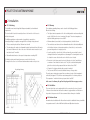
Important points to note!
In order for the stove to function properly, the following rules must be followed.
• The stove needs air in order to function, never close the supply air vent to the house.
Note that there must be at least one air supply ventilator in the room where the stove is located.
• The room temperature must exceed 5˚C for the thermostat to work.
• Your installer must adjust the stove in connection with commissioning and fill in the values in the
warranty/proof of installation at the end of these user instructions.
• The store should be emptied periodically and the sawdust removed using a vacuum cleaner.
Also test the safety switch by unlocking one of the filler hatches or the door during operation
or start-up. The pellet feeder should then be stopped.
• We recommend removing the ash daily during the firing season, or each time pellets are filled.
Remove ash through the door using the handle supplied. Lift out the burner from the burner
housing and remove any ash from the ash box (unburned pellets must not be emptied into
the ash box, there is a risk of them starting to smoulder).
• After a period of operation the glass in the door becomes coated with ash dust and eventually
becomes opaque. It should be wiped off from the inside using kitchen roll moistened with
normal tap water, we recommend that this is done each time the pellets store is filled.
(Wait until the glass has cooled). If the pane of glass becomes black and/or difficult to clean, see
section 3.6.1.
• Vacuum under the top panel’s soot hatch once between visits by the chimney sweep, the
sweep normally comes twice a year.
• Sweep your stove once a week during the firing season. Sweeping is easily done by releasing and
pulling the soot rakes backwards and forwards a few times. Slide them in and secure them again.
• Vacuum the inside of the stove annually to keep the fans clean. See section 3.5.
• If you have installed Ariterm Arrow, ash must be removed from it at least once every firing season.
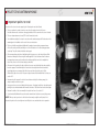
NOTE! When you start your stove for the first time there may be a slight smell of paint, this is
because the paint on the stove body must cure fully before one can obtain odour free operation.
ARITERM-SP-PX26868-B.1
ARITERM SWEDEN AB
Installation Instructions - 2013.10.10 - 3/20
PELLET STOVE ARITERM MYSINGE
ARITERM-SP-PX26868-B.1
ARITERM SWEDEN AB
Installation Instructions - 2013.10.10 - 4/20
PELLET STOVE ARITERM MYSINGE
Table of Contents
1 Product description
Product description
1.1General . . . . . . . . . . . . . . . . . . . . . . . . . . . . . . . . . . . . . . 5
1.2Components . . . . . . . . . . . . . . . . . . . . . . . . . . . . . . . . . . 6
1.3 Technical data . . . . . . . . . . . . . . . . . . . . . . . . . . . . . . . . . 7
1.4 Control panel . . . . . . . . . . . . . . . . . . . . . . . . . . . . . . . 7-8
1.5 Safety system . . . . . . . . . . . . . . . . . . . . . . . . . . . . . . . . . . 9
1.6Settings . . . . . . . . . . . . . . . . . . . . . . . . . . . . . . . . . . . . . . 9
1.6.1 Control duration . . . . . . . . . . . . . . . . . . . . . . . . . . . . . . 10
Installation
2.1Positioning . . . . . . . . . . . . . . . . . . . . . . . . . . . . . . . . . . .
2.2Chimney . . . . . . . . . . . . . . . . . . . . . . . . . . . . . . . . . . . .
2.3Ventilation . . . . . . . . . . . . . . . . . . . . . . . . . . . . . . . . . . .
2.4 Ariterm Arrow . . . . . . . . . . . . . . . . . . . . . . . . . . . . . . . .
2.5 Electrical connection . . . . . . . . . . . . . . . . . . . . . . . . . . .
2.6Documentation . . . . . . . . . . . . . . . . . . . . . . . . . . . . . . .
11
11
11
11
12
12
Operation and maintenance
3.1Fuel . . . . . . . . . . . . . . . . . . . . . . . . . . . . . . . . . . . . . . . . 13
3.2 Ash removal . . . . . . . . . . . . . . . . . . . . . . . . . . . . . . . . . 13
3.3Glass . . . . . . . . . . . . . . . . . . . . . . . . . . . . . . . . . . . . . . . 13
3.4Sweeping . . . . . . . . . . . . . . . . . . . . . . . . . . . . . . . . . . . 14
3.5 Hot air fan . . . . . . . . . . . . . . . . . . . . . . . . . . . . . . . . . . . 14
3.6 Operating stoppage . . . . . . . . . . . . . . . . . . . . . . . . . . . . 14
3.6.1 Fault tracing and remedy . . . . . . . . . . . . . . . . . . . . . 15-16
Removal
4.1Burner . . . . . . . . . . . . . . . . . . . . . . . . . . . . . . . . . . . . . .
4.2 Firing element . . . . . . . . . . . . . . . . . . . . . . . . . . . . . . . .
4.3 Combustion fan . . . . . . . . . . . . . . . . . . . . . . . . . . . . . . .
4.4 Flame detector . . . . . . . . . . . . . . . . . . . . . . . . . . . . . . . .
4.5 Hot air fan . . . . . . . . . . . . . . . . . . . . . . . . . . . . . . . . . . .
4.6 Control circuit board . . . . . . . . . . . . . . . . . . . . . . . . . . .
4.7Fuses . . . . . . . . . . . . . . . . . . . . . . . . . . . . . . . . . . . . . . .
4.8 Overheat protection and safety switches . . . . . . . . .
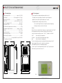
1.1 General
The stove has been developed to work as a primary heat source. The stove’s high level of
efficiency, in combination with automatic operation, means that the stove replaces up to 80
% of the heating in a normal family house with electricity as heating source. The stove is
designed for firing with wood pellets and requires an electrical power supply. In the event of
a power failure, the stove requires power from another power source (optional extra).
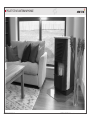
The integrated convection fan distributes the hot air around the house, for best effect the
stove should be centrally located on the lower floor of the house. The room temperature
is easily set from the control panel. During thermostatic operation the stove is ignited and
extinguished automatically.
Pellets are filled through two hatches on the top of the stove. The filler hatches and door
are equipped with safety switches. Three safety thermostats are mounted together with the
switches in a safety coil to prevent overheating.
Connection to the chimney can be either upwards or to the reverse.
The stove must not be used as an incinerator and must only be fired using wood pellets
acc. to EN 14961.
NOTE! The stove’s surfaces on and around the glass become extremely hot.
17
17
17
17
18
18
18
18
Warranty
Warranty parts . . . . . . . . . . . . . . . . . . . . . . . . . . . . . . . . 18
Declaration of conformity . . . . . . . . . . . . . . . . . . . . . . . 19
ARITERM-SP-PX26868-B.1
ARITERM SWEDEN AB
Installation Instructions - 2013.10.10 - 5/20
PELLET STOVE ARITERM MYSINGE
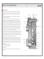
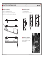
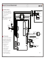
1.2 Components
The top (1) lies loose on top of the stove, with two guide lugs or is locked with quick
release locks. The top is lifted to access the cleaning hatch (2). When there is a hatch it
is opened by removing the four screws, one can then sweep the flue (3) and the smoke
tubes (4).
The flue can easily be turned through 90˚, which makes it possible to connect it to the
chimney vertically or horizontally.
The front (5) can be opened. This is how one accesses the soot scrapers (6). These (four
per handle) can be slid forwards and backwards, and scrape off the soot between the
smoke tubes. The door (7) is opened with the handle supplied and can be swung up on its
two adjustable hinges. The burner housing (8) is located in the hearth and is accessible
when the door has been opened. It is installed with four screws on the rear of the stove body.
The burner (9) sits loose in the burner housing. The firing element (10) is located in the
burner housing behind the burner. It is the firing element that gives off the heat required to
ignite the pellets. The flame sensor (11) is beside the ignition unit and indicates if there is
flame in the burner or not. The ash box (12) is inset in the bottom of the hearth under the
burner housing. It can be removed when the door has been opened.
Cleaning hatch (2)
Filling hatch (18)
Top (1)
Flue (3)
Smoke tubes (4)
Front (5)
Soot scraper (6)
Pellet hopper (17)
Door (7)
The combustion fan (13) is placed on the rear of the burner housing and provides the burner
with air for combustion. The control circuit board (15) is placed inside the stove and contains
a transformer for 12V-voltage to the electronics and control and supervision. The hot air fan
(16) is located inside the stove and sucks air from the rear of the stove, which is then heated
up in the smoke tubes and expelled through the holes in the front.
The pellet hopper (17) has space for 38 litres of pellets, and is filled through the filler hatches
(18). There is a hatch on each side, so that one can place the stove in a corner if one so
wishes. The pellet feeder (19) is below the pellet hopper and consists of a rotating cylinder
with a spiral spring that slowly turns at the bottom of the hopper and prevents blockages.
The patented design means that pellets cannot stick in the feeder. Safety thermostats (20)
are located on the:
1. fall pipe from the pellet feeder (85˚C),
2. the pellet feeder front wall (85˚C) and
3. the flue (204˚C)
The stove must not be modified and only spare parts recommended by the manufacturer
may be used.
ARITERM-SP-PX26868-B.1
Safety thermostats (20)
Pellet feeder (19)
Hot air fan (16)
Control card (15)
Burner housing (8)
Burner (9)
Flame sensor (11)
Ash box (12)
Combustion fan (13)
Firing element (10)
Sound trap
Fig. 1
ARITERM SWEDEN AB
Installation Instructions - 2013.10.10 - 6/20
PELLET STOVE ARITERM MYSINGE
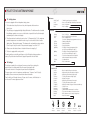
1.3 Technical data
1.4 Control panel
Heating output HI / LO...................................... approx. 6 / 3,5 kW
Pellet hopper....................................38 litres (approx. 20 - 25 kg*)
Efficiency level HI / LO......................................... approx. 91 / 91%
CO HI / LO............................................0,012 / 0,014% at 13% O2
Smoke temperature HI / LO.......................................... 160 / 110˚C
Flue gas fan HI / LO...................................................... 4.8 / 2.8 g/s
The control panel has a display and adjustment dial (see fig. 3):
- The display shows the operating mode and the current temperature.
Explanatory text scrolls through the display every 5 seconds.
- The adjustment dial is used by pressing or turning.
Recommended negative pressure in chimney.........................10 Pa
Temperature range thermostat.............................approx. 10 - 30˚C
Weight...................................................................... 100 - 138 kg
Electrical connection................................................... 230 V 50 Hz
Electrical output (firing)........................................................ 450 W
Electrical output (operation)................................................... 20 W
Fuel .....................................wood pellets Ø6 or 8 mm, EN 14961.
* Depending on fuel density.
550
- Turn to scroll through the menu or change the value when adjusting.
- Pushing once makes a selection in the menu.
Example:
Connect the stove to the wall socket. Pressing once causes the panel to ask “Start?”.
Pressing again means that you confirm the question and the stove starts.
If you turn clockwise instead you come to “Stop T”,“UserMenu” and “Back”.
560
Stop T:
Press to adjust stop temperature..
Usermenu:
Press to adjust time and temperature settings.
Back:
Press to return to the starting point.
The stove is started by pressing the control panel dial and confirming. “Start?”
by pressing again. Take care not to start the stove when there
are flammable objects above or immediately adjacent!
To shut off, press the control panel dial and confirm “Stop?” by pressing once.
867 ± 5
947
Ø76
Other menu steps are shown in section 1.6.
Fig. 3
ARITERM-SP-PX26868-B.1
ARITERM SWEDEN AB
Installation Instructions - 2013.10.10 - 7/20
PELLET STOVE ARITERM MYSINGE
Installing the control panel
Removing the control panel
1. Install the wall mounting with 2 screws.
1. Slide the panel straight up.
2. Hook one corner of the panel onto the wall mounting.
2. Lift the panel straight out from the wall
3. Press the other corner of the panel onto the wall mounting.
2
2
1
1
Connecting the control panel
Connect the control panel in the modular
connection on the side of the control
circuit board (image).
3
ARITERM-SP-PX26868-B.1
ARITERM SWEDEN AB
Installation Instructions - 2013.10.10 - 8/20
PELLET STOVE ARITERM MYSINGE
1.5 Safety system
The stove is equipped with five independent safety systems.
1. The feeder releases the pellets from a chute, which separates the burner from
the fuel store.
2. The pellet hopper is equipped with tight fitting filler hatches. The hatches must be closed and
locked during operation, as soon as one of the hatches is opened the fuel feed is interrupted
and warning text is shown on the display.
3. Three thermostats are located as shown in section 1.2 Components (fig 1). If the maximum
permitted temperature is exceeded the feeder stops, the stove switches itself off and the
display shows “Operational stoppage”. The alarm must be confirmed by pressing a button.
Do not forget to rectify the cause of the operational stoppage. See section 3.6.1.
4. A flame sensor that detects flames is located in the burner housing (fig 1).
5. The door is equipped with a safety switch.
The safety switches are tested by unlocking one of the filler hatches during operation or
start-up. The pellet feeder should then be stopped. Repeat with the other hatch.
1.6 Settings
The settings are made in the control panel in a menu system. Before entering the
menu the panel is in display mode. Enter the menu by pressing the dial.
If the menu is inactive for a long time the panel returns to display mode.
The menu system consists of a main menu and sub-menus “Usermenu” and “Settings”.
In addition, there are menus only intended for authorised installers.
Turn the dial to scroll through the menu. To jump out of the menu, hold the button in
for 4 seconds. The menu appears as follows:
Main menu
Start? (Stop?)
Stop T
Usermenu
Back
Confirm by pressing once to start (stop).
Press to select and adjust desired stop temperature.
Press for Usermenu.
Press for display.
Usermenu
Settings
Service
View
- Press for Settings.
- Menu for authorised service technicians.
- Press for Display menu
(See levels, operating time, programme version etc.)
- Limited operating time.
- Start at desired time.
- Stop at desired time.
- Possibility of lowering temperature below
specific time period during the day (1).
- Possibility of lowering temperature below
specific time period during the day (2).
- Set the lower temperature that is required
when maintenance heating is activated.
- Set date and time.
- Press for main menu.
OnTimer
TimeStrt
TimeStop
NghtDrop
DayDrop
Assist.H
Clockset
Back
Settings
SetCode (021)
Service
Ign.dose
FeedHI
TstHdose
LoPowOn
FeedLO
TstLdose
TempDiff
AudioOff
Language
ResOnLog
Res#Ign
Default?
Back
Flame
Indicated
ARITERM-SP-PX26868-B.1
-
-
Firing element
Activated
Menu for authorised service technicians.
Adjust and test the pellet amount at ignition.
Adjust the pellet amount at high output.
Test the pellet amount at high output.
Activate low output.
Adjust the pellet amount at low output.
Test the pellet amount at low output.
Adjust the number of degrees between start and stop.
Sound off or on.
Select language.
Operational time measurement is reset here.
The counter for number of firings is reset here.
All the values are reset to factory settings here.
Press for Usermenu.
Feeder motor
Activated
Combustion fan
Activated
ARITERM SWEDEN AB
Fault function
Indicated
Stove
in operation
Installation Instructions - 2013.10.10 - 9/20
PELLET STOVE ARITERM MYSINGE
1.6.1 control process
Otherwise the electronics manage all processes as follows:
• START
Time
Events
0 secs
• Firing element on.
• The firing element symbol illuminates.
120 secs
• The motor symbol illuminates.
• The feeder starts.
220 - 330 secs
• The feeder stops (Starter dose).
• The combustion fans starts pulsing and stops twice.
• The motor symbol goes out.
Approx 6 min
• Hot air fan on.
• If the flame sensor indicates
flame, the firing element is shut
off, the flame symbol illuminates
and the firing element symbol
goes out.
Approx 8 min
Approx 10 min
• LOW OUTPUT
Comments
The time depends on the set pellet
amount at ignition.
Pellet level should be approx. 5
mm above the firing element hole.
Time
Runs from 1.8 - 6 seconds every
10th second.
• Operating phase.
The thermostat regulates the
output according to the set values.
• ”LoPower” scrolls through the
display.
• The feeder runs according to
”FeedLO”
• Combustion fan ”Fan LO”
The time depends on the set
pellet amount at low output.
Every 10 seconds.
• Set temperature and room
temperature are compared.
If the room temperature reaches
the set stop temperature, the program switches to extinguishing and
then to ”Standby”.
• The flame sensor is checked
If no flame is detected, the exclamation mark illuminates and the stove
goes into “Operational stoppage”
mode.
• EXTINGUISHING
0 secs
Every 10 seconds.
ARITERM-SP-PX26868-B.1
• The feeder stops
• Combustion fan runs at max.
• HIGH OUTPUT
After “START”.
• The hot air fan runs
• ”HiPower” scrolls through the
display.
• The feeder runs according to
”FeedHi”.
• Combustion fan ”Fan HI”
The time depends on the set fuel
amount at high output.
• Set temperature and room
temperature are compared.
If the room temperature falls below
the set temperature by less than 1˚C
the program switches to low output.
• The flame sensor is checked
If no flame is detected, the exclamation mark illuminates and the stove
goes into “Operational stoppage”
mode.
Comments
After "Start".
The flame symbol is displayed as
long as the flame sensor indicates
a flame.
• The feeder on at low output.
• Maximum time for firing element.
Events
6 min
To blow ash out of the burner
crucible
• Combustion fan stops
• The hot air fan stops
ARITERM SWEDEN AB
Installation Instructions - 2013.10.10 - 10/20
PELLET STOVE ARITERM MYSINGE
2 Installation
2.2 Chimney
2.1 Positioning
The installation must meet all applicable European standards, local and national
requirements.
The regulations regarding chimneys can be found in the Building regulations.
Observe the following:
The stove should be located in a central position on the lower floor of the house to
facilitate heat spread.
•The highest surface temperature of the flue including insulation and surrounding shaft
may be 100˚C when the stove is running at full output. The surface temperature of
adjacent building parts may not exceed 80˚C.
The Building regulations contain a number of regulations to prevent fires.
Generally speaking, the regulations are applied if the following is being observed:
• The stove must be placed at least 100 mm from the wall.
• The underlay must be made of non-flammable material, and extend at least 300 mm to
the front and 100 mm to the side of the stove. If the hearth surface is made of steel it
must be at least 0.7 mm thick.
• Flammable material must not be exposed to temperatures exceeding 80˚C.
To facilitate servicing and cleaning, leave space on each side of the stove.
The weight of the stove is so low that no extra demands are made on the joists etc.
Any existing chimney
• Minimum diameter (round duct) or side (rectangular duct) should be 80 mm.
• The smoke ducts must be made of non-flammable material of sufficient durability and
with sufficient resistance to temperature variations, climate effects, corrosive smoke
gases and slag and use of sweeping tools etc.
• It must be possible to clean the flue. If fallen ash cannot be removed via the stove’s
cleaning hatch another cleaning hatch must be arranged. The cleaning hatch must not
be located in a room other than the one in which the stove is located.
• Connection to the chimney must be via a steel flue pipe of at least 2 mm thickness,
or minimum 1 mm thickness if stainless steel. The joint is sealed with hard packed
glass fibre or elastic sealing compound that can tolerate at least 250˚C.
• All parts of the chimney situated outdoors must be insulated.
• The stove must NOT be connected to divided chimneys or flue gas ducts.
The smoke gases contain water vapour that can condense to water if the temperature is
sufficiently low (approx 55°C) which can cause damage both to the chimney and stove.
The temperature 1 m below the chimney top must be at least 60˚C.
In the event of a chimney fire, pull out the plug and call the emergency services.
2.3 Ventilation
There must be at least one air supply ventilator in the room where the stove is located.
If there are other exhaust fans increase the number of supply ventilators until the fans no
longer affect the pressure ratio. We also recommend that a chimney fan is installed.
2.4 Ariterm Arrow
Information about installation with Ariterm Arrow instead of a traditional chimney is available
in a separate manual. See Arrow Wall fan Installation and Operation instructions.
Fig. 7
ARITERM-SP-PX26868-B.1
ARITERM SWEDEN AB
Installation Instructions - 2013.10.10 - 11/20
PELLET STOVE ARITERM MYSINGE
2.5 Electrical connection
The back of the stove is equipped with a
1.5 m long cable with plug, which must be
connected to a 230 V 50 Hz mains supply.
The internal wiring diagram
is shown in fig. 8.
black
red
4/ 5
1/ 2
Light sensor
Combustion fan
brown
Ignition element
Connector
blue
red
white
Ignition unit
J5
Remote
(option)
Tacho sensor
(option)
9/ 10
orange
6/ 7
NOTE! If the connection cable is damaged
it must be replaced by one of the same
type, contact the dealer.
Trafo
black
black
orange
black
red
black
red
black
black
white
orange
black
red
black
black
J10
J4
orange
black
brown
black
gray
black
PE
J6
PWM Out
(option)
yellow/green
brown
230 VAC
blue
2.6 Documentation
ARITERM-SP-PX26868-B.1
J9
J8
RS485
black
green
blue
brown
red
red
M
Feeder motor
J1
black
Convector fan
white
blue
J3
red
Safety switches
white/glass fiber
black
blue
Control panel
The stove must be installed, inspected and
commissioned by an authorised engineer.
At installation, the following data must be
collected and gathered under the section
Warranty and Installation proof.
• Manufacturing number
• Installation date
• Vacuum in chimney (cold)
• Vacuum in chimney (hot)
• Outdoor temperature
• Smoke gas temp at max operation
• Carbon dioxide content (CO2)
• Distance to combustible material
FUSES
2 x 3,15 AT
brown
grey
Fig. 8
ARITERM SWEDEN AB
Installation Instructions - 2013.10.10 - 12/20
PELLET STOVE ARITERM MYSINGE
3 Operation and maintenance
The stove is designed for a long service life, motors and other moving parts are of a very high
quality. All bearings are lifetime lubricated and the only preventative maintenance that is
normally required is sweeping and cleaning
3.1 Fuel
The stove must be lit with wood pellets, 6 or 8 mm, class 1 according to Swedish standard.
The pellets are supplied in plastic sacks that can be stacked on pallets or other suitable surfaces. Avoid exposing the sacks to moisture or mechanical stresses (vibrations or blows). Careless
handling of pellets can easily reduce them to sawdust, which can cause feed and combustion
problems. Fill the hopper with pellets slowly and without too great a drop. The store should
be emptied periodically and the sawdust removed using a vacuum cleaner.
The hopper is filled by opening the hatches above the pellet magazine.
The different stove models have different types of hatches. Where there is a knob the hatch
is opened by turning the knob a 1/4 turn anti-clockwise. To fully fill the magazine one has to
open the other hatch. The hopper can be filled while the stove is running, but because the
feeder switches off when the hatches are opened, you only have a few minutes before the
hatch must be locked again. If the hatch is open for longer, the flame is likely to get so low
that the stove will switch itself off, after which it must be restarted again. .
3.2 Ash removal
The amount of ash that build up in the burner varies depending partially on how the stove
is fired (number of starts and stops, division between full and half speed), and partially on
the quality of the pellets. The ash content varies between different pellets, but can also differ
between different batches from the same factory. This can only be established through trial
and error, but generally the ash layer in the bottom should be a maximum of a centimetre
deep. We recommend removing the ash daily during the firing season, or each time pellets
are filled.
Remove ash through the door using the handle supplied. Lift out the burner from the burner
housing and remove any ash from the ash box. Certain pellets generate a hard cake of cinders, this may need to be broken up using a screwdriver or removed using one’s hands.
Ash from the stove must be stored in a container made of non-flammable material, for
example a metal bucket, until it has cooled sufficiently that it can be held in one’s hand.
It can then be thrown away, bear in mind that wood ash contains nutrients that can be
beneficial to gardens.
3.3 The glass
After a period of operation the glass in the door becomes coated with ash dust and
eventually becomes opaque. It should, therefore, be wiped off from the inside using
kitchen roll moistened with normal tap water, we recommend that this is done each
time the pellets store is filled. No cleaning agent is usually necessary.
If the pane of glass becomes black and/or difficult to clean, see section 3.6.1.
When cleaning the black painted metal components only water and in certain cases
washing up liquid should be used.
ARITERM-SP-PX26868-B.1
ARITERM SWEDEN AB
Installation Instructions - 2013.10.10 - 13/20
PELLET STOVE ARITERM MYSINGE
3.4 Sweeping
The chimney must be swept twice a year. Remove the cleaning hatch, under the
top plate / stone (4 x Allen screws).
The flue and its connection and the area underneath the cleaning hatch must be
cleaned at least once between the chimney sweep’s visits.
Sweeping of the stove is carried out once a week during the firing
Measurement hole
season using the integrated soot rakes. They are located behind
the front panel and must be pulled backwards and forwards
a couple of times each, starting from above.
Remove the soot rakes as follows:
1. The silicon seal seals against the stove body.
2. Slacken off the nut a couple of turns.
3. Press the soot rake upwards or downwards.
4. Pull the soot rakes (in pairs) straight out.
5. The soot rakes are sealed in reverse order.
The chimney must be checked for blockages
if unused for a prolonged period.
Use the handle for the door to open the front of Ariterm Mysinge.
Slide the handle diagonally upwards and then to the side (see above).
3.5 Hot air fan
Vacuum cleaning of the fans with a brush nozzle should be carried out a couple of times
annually after removing the side hatch.
Do not forget to pull the plug out before the side hatch is removed.
The side hatch is secured using two panel screws that are visible when the filling hatch has
been opened. After the screws have been removed the upper section of the side hatch is
pulled straight out and hooked onto the side member.
NOTE! When vacuuming the hot air fan, be careful not to damage the long and
vulnerable fan blades.
The fan bearings can start to whistle after operating for some time in a dusty environment.
Rectify this with a drop of oil on both bearings.
3.6 Operating stoppage
If the stove does not start, check first where the fault is located using the fault-tracing
diagram below. If you consider that you have the necessary expertise, rectify the fault as
suggested. If not, or if the fault cannot be located, contact your dealer.
After an unsuccessful start attempt or operating stoppage, the burner crucible
must always be emptied!
ARITERM-SP-PX26868-B.1
ARITERM SWEDEN AB
Installation Instructions - 2013.10.10 - 14/20
PELLET STOVE ARITERM MYSINGE
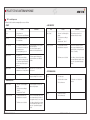
3.6.1 Fault tracing and remedy
Fault
Black ash or soot on
the glass.
The ash becomes a
hard cake.
Smoke odour.
Condensation leaks
from the stove’s flue
connection.
Cause
Action
• Too much ash in the crucible or
blocked vent.
Clean the burner crucible.
•Dirty combustion fan.
Clean the combustion fan.
• Incorrectly adjusted fuel or air
amount.
See Menu.
• Incorrectly adjusted fuel or air
amount.
See Menu.
•The fuel has a too low ash
melting temperature.
Contact the fuel supplier.
•Blocked smoke access.
Clean the stove see 3.4.
•Contaminated convection
ducts.
Clean the stove see 3.4.
• Negative pressure in the house.
Ensure that the stove has the
necessary ventilation.
•Flue smoke too cold for the
chimney.
Increase the output by adjusting
the amount of fuel and air.
Cause
Fault
The stove does
not start, nothing
displayed.
Action
•The cable is not connected.
Connect to earthed 230V socket.
•No voltage at the socket.
Check the fuse.
• Stove fuse blown.
Replace the fuse, see section 4.7.
• The cable between the control
panel and the control circuit
board is not correctly
connected.
Check that the lead is connected
at both ends.
Deactivate low output.
Insulate the chimney.
Install condensation trap.
The stove is in
”Standby” mode.
ARITERM-SP-PX26868-B.1
• The room temperature exceeds
the set stop temperature.
Set the desired stop temperature.
•The room temperature must
exceed 5˚C for the thermostat
to work.
Increase ”Stop T” above 30˚C to
start in ”On-mode”. When the
room temperature has exceeded
5˚C, adjust the desired stop
temperature.
In the event of an unsuccessful start attempt or
operating stoppage, the burner crucible must
always be emptied!
ARITERM SWEDEN AB
Installation Instructions - 2013.10.10 - 15/20
PELLET STOVE ARITERM MYSINGE
Error codes
Error code
Cause
Action
Powfail.
•Power failure.
Check the electrical connection.
Errign:
The firing element
is not drawing any
power.
•Poor contact to firing element.
Check wiring and connections.
•Defective firing element.
Replace firing element.
ErrSafe:
The flame sensor has
not detected a flame
when the safety coil
has been broken.
•One of the safety thermostats
has deployed.
Check the fuel volume, and that
the hot air fan functions. Clean the
convection tubes. Reset by pressing
on the panel.
ErrStart:
The flame sensor has
not detected a flame
during the start-up
phase.
• One of the hatch switches is
not switched on.
Fill up the pellets.
•Pellets have jammed in the
feeder.
Remove pellets from the chute.
Ensure that there are no foreign
objects in the chute.
•The feeder auger does not
rotate.
Check that there are no foreign
objects stuck in the feeder auger.
Check switches and wiring to the
motor.
ARITERM-SP-PX26868-B.1
Error code
ErrorHI:
The flame sensor has
not detected a flame
during high output.
Cause
Action
• Incorrectly adjusted fuel and/or
air amount.
("FeedHI" or "Fan HI")
See Menu.
•The hopper is empty.
Fill up the pellets.
• Pellets have jammed in the
feeder.
Remove pellets from the chute.
Ensure that there are no foreign
objects in the chute.
• The feeder auger does not
rotate.
Check that there are no foreign
objects stuck in the feeder auger.
Check switches and wiring to the
motor.
Ensure that the hatch and door is
properly closed. A weak clicking
noise must be heard when closed.
•The hopper is empty.
•Incorrectly adjusted starting
dose. (”lgn.dose”)
Replace motor.
ErrorLO:
The flame sensor has
not detected a flame
during low output.
• Incorrectly adjusted fuel and/or
air amount.
("FeedLO" or "Fan LO")
See Menu.
•The hopper is empty.
Fill up the pellets.
• Pellets have jammed in the
feeder.
Remove pellets from the chute.
Ensure that there are no foreign
objects in the chute.
• The feeder auger does not
rotate.
Check that there are no foreign
objects stuck in the feeder auger.
Replace motor.
Check switches and wiring to the
motor.
See Menu.
Replace motor.
ARITERM SWEDEN AB
Installation Instructions - 2013.10.10 - 16/20
PELLET STOVE ARITERM MYSINGE
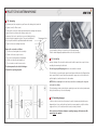
4 Removal
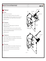
4.1 Burner
Flame detector
Burner
Terminal block
1. Open the door and remove the ash box.
Combustion fan
2. Remove the four screws holding the burner flange to the stove wall (fig 10).
3. Pull the burner straight out until the cables connecting the burner to the control circuit
board are visible. Pull the two connectors apart. The burner can now be removed.
4. Reinstall in reverse order.
(2)
4.2 Firing element
1. Remove the burner as above.
(1)
2. Remove the four screws (1) holding the upper part of the ignition bracket.
The firing element is now free.
3. Disconnect the firing element’s cables from the triac control and the terminal block.
4. Slacken off the screw (3) that secures the firing element. Remove the firing sleeve from
the element. Pull out the cables from the lead-ins.
Standard (3)
5. Reinstall in reverse order.
Terminal block
4.3 Combustion fan
1 Remove the burner and the ignition console according to the Firing element section.
2. Remove the red and the blue cable from the terminal block on the side of the bracket.
3. Remove the screws (2) holding the fan to the bracket.
4. Reinstall in reverse order.
4.4 Flame detector
1. Remove the burner and the ignition console according to the Firing element section.
2. Remove the white cables from the terminal block in the side of the bracket.
3. Remove the flame sensor, but first note how it sits at the side of the bracket.
4. Reinstall in reverse order.
Drag
Fig. 10
ARITERM-SP-PX26868-B.1
ARITERM SWEDEN AB
Installation Instructions - 2013.10.10 - 17/20
PELLET STOVE ARITERM MYSINGE
5 Warranty
4.5 Hot air fan
Work is best carried out with both side hatches removed, but they can also be accessed
from one side or the other.
For warranty issues Ariterm Sweden AB refers to our local Distributor.
1. Remove the plug from the wall socket.
2. Open the top and slacken off the two panel screws on the upper edge of the side hatch.
3. Pull the upper section of the hatch straight out and then lift up the panel so that it is free.
4. Disconnect the cables from the fan by pulling the plastic covered flat pin sleeves from
the motor.
5. Remove the screws that hold the fan brackets to the stove body (2 x).
6. Reinstall in reverse order.
4.6 Control circuit board
1. Remove the plug from the wall socket.
2. Remove one of the side hatches according to the Hot air fan section.
3. Remove the edge connectors on the long sides of the control circuit board by pulling
them straight out from the circuit board.
4. Disconnect the cable for the control panel located in a connector on one edge of the
control circuit board. Press in the hook on the underside of the connector and pull the
cable straight out to the side.
5. Release the three panel screws on the rear of the stove and remove the control
circuit board.
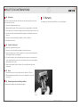
4.7 Fuses
1. There are two fuses on the stove’s input connector. Both are 3.15A slow.
2. When replacing the fuses pull the connector cover straight out to access the
fuses (Fig. 11).
4.8 Overheat protection and safety switches
This work must be carried out by an authorised engineer.
Fig. 11
ARITERM-SP-PX26868-B.1
ARITERM SWEDEN AB
Installation Instructions - 2013.10.10 - 18/20
PELLET STOVE ARITERM MYSINGE
The Clean Air Act 1993 and Smoke Control Areas
Under the Clean Air Act local authorities may declare the whole or part of the district of
theauthority to be a smoke control area. It is an offence to emit smoke from a chimney of
a building, from a furnace or from any fixed boiler if located in a designated smoke control
area. It is also an offence to acquire an “unauthorised fuel” for use within a smoke control
area unless it is used in an “exempt” appliance (“exempted” from the controls which
generally apply in the smoke control area).
The Secretary of State for Environment, Food and Rural Affairs has powers under the Act to
authorise smokeless fuels or exempt appliances for use in smoke control areas in England.
In Scotland and Wales this power rests with Ministers in the devolved administrations for
those countries. Separate legislation, the Clean Air (Northern Ireland) Order 1981, applies in
Northern Ireland. Therefore it is a requirement that fuels burnt or obtained for use in smoke
control areas have been “authorised” in Regulations and that appliances used to burn solid
fuel in those areas (other than “authorised” fuels) have been exempted by an Order made
and signed by the Secretary of State or Minister in the devolved administrations.
Further information on the requirements of the Clean Air Act can be found here :
http://smokecontrol.defra.gov.uk/
Your local authority is responsible for implementing the Clean Air Act 1993 including
designation and supervision of smoke control areas and you can contact them for details
of Clean Air Act requirements
The Ariterm Mysinge pellet stove has been recommended as suitable for use in smoke
control areas when burning wood pellets.
ARITERM-SP-PX26868-B.1
ARITERM SWEDEN AB
Installation Instructions - 2013.10.10 - 19/20
PELLET STOVE ARITERM MYSINGE
If these instructions are not followed at installation, operation
and maintenance, Ariterm Sweden AB’s applicable warranties are not binding.
Ariterm reserves the right to make changes to components and specifications
without prior notice.
Ariterm Sweden AB
Flottiljvägen 15, SE-392 41 Kalmar
www.ariterm.se
ARITERM-SP-PX26868-B.1
ARITERM SWEDEN AB
Installation Instructions - 2013.10.10 - 20/20