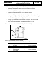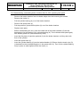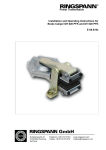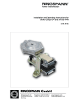
1
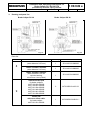
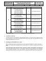
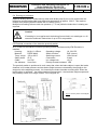
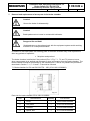
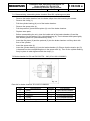
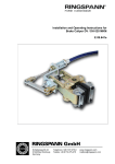
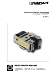
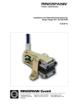
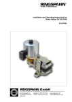
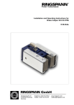
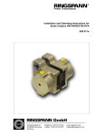
® Power Transmission Installation and Operating Instructions for Brake Caliper DV / DH 030 PFK E 09.649e Schaberweg 30-34 61348 Bad Homburg Germany Telephone +49 6172 275-0 Telefax +49 6172 275-275 www.ringspann.com [email protected] Installation and Operating Instructions for Brake Caliper DV / DH 30 PFK pneumatically activated, spring released Issue: 03.04.2014 Version :8 drawn: Su checked.: Su E 09.649 e pages: 15 page: 2 IMPORTANT Please read these instructions carefully before installing and operating the product. Your particular attention is drawn to the notes on safety. These installation and operating instructions are valid on condition that the product meets the selection criteria for its proper use. Selection and design of the product is not the subject of these installation and operating instructions. Disregarding or misinterpreting these installation and operating instructions invalidates any product liability or warranty by RINGSPANN; the same applies if the product is taken apart or changed. These installation and operating instructions should be kept in a safe place and should accompany the product if it is passed on to others -either on its own or as part of a machine- to make it accessible to the user. SAFETY NOTICE Installation and operation of this product should only be carried out by skilled personnel. Repairs may only be carried out by the manufacturer or accredited RINGSPANN agents. If a malfunction is indicated, the product or the machine into which it is installed, should be stopped immediately and either RINGSPANN or an accredited RINGSPANN agent should be informed. Switch off the power supply before commencing work on electrical components. Rotating machine elements must be protected by the purchaser to prevent accidental contact. Supplies abroad are subject to the safety laws prevailing in those countries. Installation and Operating Instructions for Brake Caliper DV / DH 30 PFK pneumatically activated, spring released Issue: 03.04.2014 Version :8 drawn: Su checked.: Su Contents 1. General information 2. Configuration and function 3. Drawing and parts list 4. Condition on delivery 5. Installing the RINGSPANN brake caliper 5.1 Installation 5.2 Compressed air connection 5.3 Adjusting the brake caliper 5.4 Running-in procedure 5.5 Inductive proximity switch 6. Maintenance 6.1 General maintenance 6.2 Checking and adjusting the brake gap 6.3 Checking brake pad wear 7. Removal and replacement of worn parts in the brake chamber 7.1 Brake chamber for DV and DH 030 650 7.2 Brake chamber for DV and DH 030 640 7.3 Brake chamber for DV and DH 030 653 E 09.649 e pages: 15 page: 3 Installation and Operating Instructions for Brake Caliper DV / DH 30 PFK pneumatically activated, spring released Issue: 03.04.2014 1. Version :8 drawn: Su checked.: Su E 09.649 e pages: 15 page: 4 General information These installation and operating instructions apply to: the DV / DH 030 PFK, with either a 640, 650 or 653 brake chamber the DV 030 PFK, brake caliper mounted parallel to the brake disc (frame construction V, see Fig. 3.1 in Section 3); brake chamber mounted on the right. the DH 030 PFK, brake caliper mounted at a right angle to the brake disc (frame construction H, see Fig. 3.2 in Section 3); brake chamber mounted on the right. the DV / DH 030 PFK with left-mounted brake chamber; the DV / DH 030 PFK with inductive proximity switch for installation on a brake disc with a thickness of 12,5 mm or 25 mm the special equipment with 19 mm brake gap. versions with enhanced corrosion protection various types of brake-pads, e.g. with wear alarm cable, increased glide speed, double friction surface or other special brake pad materials. An identification plate with a 16-digit part number is affixed to the calliper. The precise design of the brake calliper is defined by this part number only. Please consult the drawings in each section when using this instruction 2. Configuration and function The brake caliper is used as a stopping, control and holding brake. Braking force is generated by compressed air. The brake is released (opened) by spring force. Rotating parts must be secured by the user against inadvertent contact (e.g. brake disc). Danger to life and limb! It is essential to secure the entire drive train against inadvertent starts during brake installation and maintenance. Rotating components can cause severe injuries. Therefore, rotating components (e.g. brake disc) must be secured by the operator to prevent accidental contact. Caution! If the brakes are used as holding brakes, the braking torques specified are not met. Reduction of up to 50% of the braking torque are possible. Installation and Operating Instructions for Brake Caliper DV / DH 30 PFK E 09.649 e pneumatically activated, spring released Issue: 03.04.2014 3. Version :8 drawn: Su checked.: Su pages: 15 page: 5 Drawing and parts list Brake Caliper DV 30 Brake Caliper DH 30 Fig. 3.1 Fig. 3.2 Parts list: Part 8 9 *) Part number for 1 pad Nomenclature Brake chamber, Size 650 (other diameter 135 mm) Quantity Part number 1 3514-100112-000000 Brake chamber, Size 640 (other diameter 110 mm) 1 3514-100113-000000 Brake chamber, Size 653 (other diameter 135 mm cylinder bearing, electroless nickel plated) 1 3514-100134-000000 Standard brake pad for brake calipers: 4457-300100-000000 4457-300101-000000 4457-901124-000000 4457-901148-000000 4457-901141-000000 4457-301128-000000 2 2472-005013-A00112* Brake pad with wear alarm cable: for brake caliper: 4457-901131-000000 1 2472-005013-A00101** **) Part number for 1 set (2 pieces) brake pads Installation and Operating Instructions for Brake Caliper DV / DH 30 PFK E 09.649 e pneumatically activated, spring released Issue: 03.04.2014 Version :8 Part checked.: Su pages: 15 page: 6 Nomenclature Quantity Part number Brake pad from BK 8006 for brake calipers: 4457-300110-000000 4457-300111-000000 4457-301110-000000 4457-301128-A00109 2 2472-005013-A00109* Brake pad from BK 5300 (v = 50m/s) for brake caliper: 4457-301106-000000 2 2472-005013-A00103* Brake pad from BK 6230 for brake caliper: 4457-301112-000000 2 2472-005013-A00108* Brake pad from BK 8006 with wear alarm cable for brake caliper: 4457-301114-000000 1 2472-005013-A00113** Brake pad from BK 6905 for brake caliper: 4457-301123-000000 2 2472-005013-A00117* Brake pad from BK 5300 (v = 50m/s) for 19 mm brake gap for brake calipers: 4457-300106-000000 2 2472-005016-A00101* 9 *) Part number for 1 pad 4. drawn: Su **) Part number for 1 set (2 pieces) brake pads Condition on delivery The brake calliper is delivered with a clamping gap of approx. 13.5 mm or 26 mm between brake pads. Deviating of it the special equipment with the article code is 4457-300106-000000: here the clamping gap amounts to 19.0 mm. 5. Installing the RINGSPANN brake caliper Before installing the brake, the brake disc must be cleaned with alcohol, e.g. ethyl or isopropyl alcohol, or a water-based surfactant solution (soapy water, etc.) and then rubbed dry with a clean cloth. When cleaning the brake disc with a thinner, acetone or a brake cleaning agent, it is important to ensure that neither these cleaners nor any cleaner residues come in contact with the brake pads. This is especially important in the case of brakes used only as parking brakes, as no dynamic braking operations take place during which thinner residues would be rubbed off the brake disc. Installation and Operating Instructions for Brake Caliper DV / DH 30 PFK pneumatically activated, spring released Issue: 03.04.2014 Version :8 drawn: Su checked.: Su E 09.649 e pages: 15 page: 7 Caution! Oil and rust-proofing-agent residues reduced friction coefficient and thus diminish transmissible braking torque substantially! 5.1 Installation The brake calliper should be mounted to stabile, vibration-free machine components in order to ensure noise-free, non-screech. During installation, it is essential to ensure that brake pads are centred and in full contact with the brake disc (the midlines of the brake caliper arms must point to the midpoint of the brake disc). Maximum permissible lateral brake disc wobble is 0.2 mm. Greater wobble may cause rattling and shaking of the brake unit. The brake caliper is using: 4 M 12 bolts (DV 30) or 3 M 12 bolts (DH 30) the strength class 8.8. attached to the machine part. Caution! When mounting the brake caliper, the brake chamber cannot filled with compressed air be. 5.2 Compressed air connection A flexible hose connection is required. Please use hoses with a diameter of 6 mm. Hose pressure must be at least 7 bar (preferably 12 bar) with a temperature range of approx. - 20°C to + 80°C. Air hoses are connected to the brake chamber with a G 1/4 " fitting (Whitworth threaded pipe, DIN ISO 228-1). Operating pressure may range between 1 to 6 bar, depending on braking force, maximum pressure is 6 bar. Compressed air must be filtered to remove all dirt, pipe chips, rust and condensation. Purified air must then be enriched with a fine oil mist injected by a standard, commercially available conditioning unit. The quantity of oil added depends on the nominal air flow rate in l/min and is specified by the manufacturer of the conditioning unit. The following types of oil are recommended for conditioning units: Suitable types of oil Viscosity at 20° C (mm²/s) Avia Avilub RSL 3 BP Energol HLP 40 ESSO Spinesso 34 Shell Tellus Öl C 10 Mobil VAC HLP 9 34 27 23 22 25,2 Maximum air consumption per braking operations is: for DV 030 PFK 650 and DH 030 PFK 650 approx. 490 cm³ for DV 030 PFK 640 and DH 030 PFK 640 approx. 313 cm³ for DV 030 PFK 653 and DH 030 PFK 653 approx. 490 cm³ Installation and Operating Instructions for Brake Caliper DV / DH 30 PFK pneumatically activated, spring released Issue: 03.04.2014 Version :8 drawn: Su checked.: Su E 09.649 e pages: 15 page: 8 5.3 Adjusting the brake caliper The brake chamber must not be pressurized. The gap between the brake pads (9) and the brake disc has been set by the manufacturer to 0.5 mm on each side. If the actual dimension deviates from the specified value of 76 mm (and/or 77.8 mm with DH 30), the gap is altered accordingly. This must be corrected using the following procedure: To reduce the brake gap, turn the threaded pins clockwise. Turn the threaded pins counter-clockwise to increase the gap. Set both calliper arms to a gap of approx. 0.5 mm. Caution! Check to ensure that the brake disc rotates freely. Caution! The friction block distance must after initial assembly or after replacing the brake pads or other components be new adjusted. Caution! The friction block distance must be corrected periodically at wear of the brake pad. Caution! During installation, ensure that the brake pads are centred and in full contact with the surface of the brake disc. The gap between the brake pads and the brake disc should always be approx. 1 mm on each side. Please observe maximum the wear limit. Caution! It is important to ensure that the brake pads do not rub against the brake disc when the brake is released. Installation and Operating Instructions for Brake Caliper DV / DH 30 PFK pneumatically activated, spring released Issue: 03.04.2014 Version :8 drawn: Su checked.: Su E 09.649 e pages: 15 page: 9 5.4 Running-in procedure Optimum braking effect is achieved only when both brake pads (9) are in full contact with the brake disc and the brake pads have attained a temperature of approx. 200°C. This requires multiple, brief braking while the brake disc is rotating (run-in). Multiple brief braking actions under low pressure (1 – 2 bar) while the brake disc is rotating are required. Caution! If breaking-in is not performed, the braking forces cited in our catalogue no. 46 cannot be achieved. Reductions of up to 50% are possible. 5.5 Electrical connection of the inductive proximity switch An IF 5188 /IFB 3002-BPKG inductive proximity switch manufactured by IFM Electronic is installed: Housing: Material: Temp. range: Safety class: Cable: Sw. distance: M12x1, L=55mm PBTB/ MnNi -25 to +80°C IP 67 2m PVC 2mm flush Operating voltage: 18...36V DC Switch function: PNP (closer) Switching current: 150 mA max. Connection: 3-lead Int. voltage loss: <2,5 V Polarity reversal-resistant: YES The proximity switch is positioned in such a way that, when the brake caliper is open (the brake chamber is not under pressure and two brake caliper arms are retracted by the springs to the stop point at the adjusting screws), it is closed by the brake chamber mounting bolt. When the brake caliper is activated – the brake chamber is pressurized – the two brake calipers open and the proximity switch is no longer closed. The LED goes off. Fig. 5 2: Proximity switch circuit diagram Installation and Operating Instructions for Brake Caliper DV / DH 30 PFK pneumatically activated, spring released Issue: 03.04.2014 Version :8 drawn: Su checked.: Su E 09.649 e pages: 15 page: 10 Procedure for installing or replacing the proximity switch: The following instructions apply to the proximity switch listed above, with 2-mm switching distance. The brake chamber is not pressurized. The brake is open. Check to ensure that the brake pads are not in contact with the brake disc, i.e. that there is an equal gap (0.5 mm in the case of new pads) on both sides. Turn the hex nut on the proximity switch. Insert the proximity switch into the bore on the brake caliper and turn the second hex nut on the proximity switch thread. Position the proximity switch axially so that a 1-mm feeler gauge is lightly clamped between the active surface of the proximity switch and the brake chamber mounting bolt. Tighten the two hex nuts. Connect the proximity switch and remove the feeler gauge. The LED goes on. Test for proper function by repeatedly activating the brake caliper. When pressure is applied – the brake caliper opens – the LED must go off. 6. Maintenance Maintenance should be performed on the brake caliper at intervals of 4 to 12 weeks, depending upon the frequency and duration of operation. Danger to life and limb! When disassembling the brake it is essential to ensure that the entire drive train is secured against inadvertent activation. Rotating components can cause severe injuries. Therefore, rotating components (e.g. brake discs) must be secured against accidental contact. To prevent injuries to personnel, secure the brake with the aid of an assembly locking device. 6.1 General maintenance Check both brake caliper lever for ease of movement. Clean all bearings and glide points. Lubricate all bearing and glide points. Caution! Brake pads must not be come in contact with lubricants. Check for tight bolt / screw connections: brake caliper to machine component brake chamber to brake caliper lever brake pads to brake caliper lever Installation and Operating Instructions for Brake Caliper DV / DH 30 PFK pneumatically activated, spring released Issue: 03.04.2014 Version :8 drawn: Su checked.: Su E 09.649 e pages: 15 page: 11 Check the following for proper seal / leaks: hose connection (leaks can be detected quickly and easily using e.g., "Güpoflex LECKSUCHER", manufactured by GÜPO GmbH, 77694 Kehl, telephone ++49/7851/4044-45, or equivalent products). 6.2. Checking and adjusting the brake gap Check to ensure that the gap between the brake disc and the brake pads is equal. If necessary, adjust the gap (equal on both sides) as described in Section 5.3. 6.3 Checking brake pad wear Brake pad material must have a thickness of at least 4 mm (from the top surface of the brake pad to the top surface of the steel mounting plate). Brake pads or brake linings (Pos. 9) must always be replaced in pairs. For unscrewing and screwing on fixed spanners or ring spanners with SW 13 are needed. Turn the threaded pin which controls symmetrical gap adjustment back until the brake pads can be easily replaced. Replace the worn brake pads including carrier plates. To do so, a ring spanner or fixed spanner SW 13 is needed. Adjust the gap between the brake pads and the brake disc as described in Section 5.3. The brake is now ready for operation. Danger to life and limb! Brake pads may be replaced only when the equipment system and/or the working machine is at a complete standstill! Caution! Ensure that the brake caliper is not under air pressure before replacing the brake pads. Caution! Brake pads must not be worn to a residual thickness of less than 4 mm (mounting plate thickness plus remaining pad material). Brake pads must always be replaced in pairs. Installation and Operating Instructions for Brake Caliper DV / DH 30 PFK pneumatically activated, spring released Issue: 03.04.2014 7. Version :8 drawn: Su checked.: Su E 09.649 e pages: 15 page: 12 Removal and replacement of worn parts in the brake chamber Caution! Secure the brake for disassembly. Caution! Brake pads must not come in contact with lubricants. Danger to life and limb! Seals/gaskets may be replaced only with the equipment system and/or working machine is at a complete standstill! In addition to the brake pads, the following parts of the brake chamber may need replacement after long periods of operation: flat piston and pushrod The brake chamber is defective if the pushrod (Pos. 3, Fig. 7.1, 7.2 and 7.3) does not move when compressed air is applied and released or when air escapes from the brake chamber. The brake chamber should be overhauled by the manufacturer. If this is not possible the procedure described in Section 7.11, 7.21 and 7.31 should be followed 7.1 Brake chamber for DV and DH 030 PFK – 650 (3514-100112-000000) Fig. 7.1 Parts List for brake chamber 3514-100112-000000: Part Nomenclature Quantity Part number 1 Circlip 1 5108-125001-000000 2 Flat piston 1 2742-125103-000000 3 Pushrod 1 2722-015605-000000 4 Spacer disc 1 2711-125101-000000 Installation and Operating Instructions for Brake Caliper DV / DH 30 PFK pneumatically activated, spring released Issue: 03.04.2014 Version :8 drawn: Su checked.: Su E 09.649 e pages: 15 page: 13 7.11 Disassembling, assembling brake chamber Size 650; replacing worn parts - Remove the brake chamber from the brake caliper lever be loosening the screws. - Remove the circlip (1). - Pull the cylinder bearing (A) out of the brake chamber. - Remove the spacer disc (4). - Pull the pushrod (3) and the flat piston (2) out of the brake chamber. - Replace worn parts. - Before reassembling the unit, clean the inside wall of the brake chamber (8) and the bearing bore for the pushrod (3) in cylinder bearing (A). Then lubricate these parts lightly with Alvania grease G2 (manufactured by Shell). - Insert the flat piston (2) and the pushrod (3) into the brake chamber until they abut with floor of the cylinder. - Insert the spacer disc (4). - Insert the cylinder bearing (A) into the brake chamber (8). Ensure that the tension pin (S) is inserted into the corresponding bore in the spacer disc (4). Then fix the cylinder bearing firmly in place in axial alignment with the circlip (1). 7.2 Brake chamber for DV and DH 030 PFK – 640 (3514-100113-000000) Fig. 7.2 Parts list for brake chamber 3514-100113-000000: Part 1 2 3 4 5 Nomenclature Circlp Flat piston Pushrod O-ring Glide bushing Quantity 1 1 1 1 2 Part number 5108-102.001-000000 2742-100102-000000 2722-015610-000000 5116-092000-040090 5313-015001-000000 Installation and Operating Instructions for Brake Caliper DV / DH 30 PFK pneumatically activated, spring released Issue: 03.04.2014 Version :8 drawn: Su checked.: Su E 09.649 e pages: 15 page: 14 7.21 Disassembling, assembling brake chamber Size 640; replacing worn parts - Remove the brake chamber from the caliper lever by loosening the screws. - Remove the circlip (1). - Pull the cover (A) with the O-ring (4) out of the brake chamber. - Press the pushrod (3) and flat piston (2) out of the brake chamber. - Replace worn parts. - Before reassembling the unit, clean the inside wall of the brake chamber (8) and the bearing bore for the pushrod (3) in cylinder bearing (A). Then lubricate these parts lightly with Alvania grease G2 (manufactured by Shell). - Insert the flat piston (2) and the pushrod (3) into the brake chamber - Insert the cover (A) with the O-ring into the brake chamber (8). Then fix the cylinder bearing firmly in place in axial alignment with the circlip (1). - Before mounting the brake caliper, test for leaks at a pressure of 6-7 bar. 7.3 Brake chamber for DV and DH 030 PFK - 653 (3514-100134-000000) 4 2 3 5 1 Fig. 7.3 Parts list for brake chamber 3514-100134-000000: Part Nomenclature Quantity Part number 1 Circlip 1 5108-125001-000000 2 Flat piston 1 2742-125103-000000 3 Pushrod 1 2722-015605-000000 4 Spacer disc 1 2711-125101-000000 5 Cylinder bearing (nickel plated) 1 2772-125104-000000 Installation and Operating Instructions for Brake Caliper DV / DH 30 PFK pneumatically activated, spring released Issue: 03.04.2014 Version :8 drawn: Su checked.: Su E 09.649 e pages: 15 page: 15 7.31 Disassembling, assembling brake chamber Size Gr. 653; replacing worn parts - Remove the brake chamber from the brake caliper lever be loosening the screws. - Remove the circlip (1). - Pull the cylinder bearing (A) out of the brake chamber. - Remove the spacer disc (4). - Pull the pushrod (3) and the flat piston (2) out of the brake chamber. - Replace worn parts. - Before reassembling the unit, clean the inside wall of the brake chamber (8) and the bearing bore for the pushrod (3) in cylinder bearing (A). Then lubricate these parts lightly with Alvania grease G2 (manufactured by Shell). - Insert the flat piston (2) and the pushrod (3) into the brake chamber until they abut with floor of the cylinder. - Insert the spacer disc (4). - Insert the cylinder bearing (A) into the brake chamber (8). Ensure that the tension pin (S) is inserted into the corresponding bore in the spacer disc (4). Then fix the cylinder bearing firmly in place in axial alignment with the circlip (1).