1
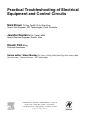
Preface
Practical Troubleshooting of Electrical
Equipment and Control Circuits
Mark Brown Pr.Eng, DipEE, B.Sc (Elec Eng),
Senior Staff Engineer, IDC Technologies, Perth, Australia
Jawahar Rawtani M.Sc (Tech), MBA,
Senior Electrical Engineer, Nashik, India
Dinesh Patil BEng,
Patil and Associates.
Series editor: Steve Mackay FIE (Aust), CPEng, B.Sc (Elec.Eng), B.Sc (Hons), MBA,
Gov.Cert.Comp., Technical Director – IDC Technologies
AMSTERDAM • BOSTON • HEIDELBERG • LONDON
NEW YORK • OXFORD • PARIS • SAN DIEGO
SAN FRANCISCO • SINGAPORE • SYDNEY • TOKYO
Newnes is an imprint of Elsevier
iii
ii
Contents
Other titles in the series
Practical Cleanrooms: Technologies and Facilities (David Conway)
Practical Data Acquisition for Instrumentation and Control Systems (John Park, Steve Mackay)
Practical Data Communications for Instrumentation and Control (Steve Mackay, Edwin Wright,
John Park)
Practical Digital Signal Processing for Engineers and Technicians (Edmund Lai)
Practical Electrical Network Automation and Communication Systems (Cobus Strauss)
Practical Embedded Controllers (John Park)
Practical Fiber Optics (David Bailey, Edwin Wright)
Practical Industrial Data Networks: Design, Installation and Troubleshooting (Steve Mackay,
Edwin Wright, John Park, Deon Reynders)
Practical Industrial Safety, Risk Assessment and Shutdown Systems for Instrumentation and Control
(Dave Macdonald)
Practical Modern SCADA Protocols: DNP3, 60870.5 and Related Systems (Gordon Clarke, Deon
Reynders)
Practical Radio Engineering and Telemetry for Industry (David Bailey)
Practical SCADA for Industry (David Bailey, Edwin Wright)
Practical TCP/IP and Ethernet Networking (Deon Reynders, Edwin Wright)
Practical Variable Speed Drives and Power Electronics (Malcolm Barnes)
Practical Centrifugal Pumps (Paresh Girdhar and Octo Moniz)
Practical Electrical Equipment and Installations in Hazardous Areas (Geoffrey Bottrill and
G. Vijayaraghavan)
Practical E-Manufacturing and Supply Chain Management (Gerhard Greef and Ranjan Ghoshal)
Practical Grounding, Bonding, Shielding and Surge Protection (G. Vijayaraghavan, Mark Brown and
Malcolm Barnes)
Practical Hazops, Trips and Alarms (David Macdonald)
Practical Industrial Data Communications: Best Practice Techniques (Deon Reynders, Steve Mackay
and Edwin Wright)
Practical Machinery Safety (David Macdonald)
Practical Machinery Vibration Analysis and Predictive Maintenance (Cornelius Scheffer and
Paresh Girdhar)
Practical Power Distribution for Industry (Jan de Kock and Cobus Strauss)
Practical Process Control for Engineers and Technicians (Wolfgang Altmann)
Practical Power Systems Protection (Les Hewitson, Mark Brown and Ben. Ramesh)
Practical Telecommunications and Wireless Communications (Edwin Wright and Deon Reynders)
Practical Hydraulics (Ravi Doddannavar, Andries Barnard)
Practical Batch Process Management (Mike Barker, Jawahar Rawtani)
Preface
Practical Troubleshooting of Electrical Equipment
and Control Circuits
i
iv Contents
Newnes
An imprint of Elsevier
Linacre House, Jordan Hill, Oxford OX2 8DP
30 Corporate Drive, Burlington, MA 01803
First published 2005
Copyright © 2005, IDC Technologies. All rights reserved
No part of this publication may be reproduced in any material form (including
photocopying or storing in any medium by electronic means and whether
or not transiently or incidentally to some other use of this publication) without
the written permission of the copyright holder except in accordance with the
provisions of the Copyright, Designs and Patents Act 1988 or under the terms of
a licence issued by the Copyright Licensing Agency Ltd, 90 Tottenham Court Road,
London, England W1T 4LP. Applications for the copyright holder’s written
permission to reproduce any part of this publication should be addressed
to the publisher
British Library Cataloguing in Publication Data
Brown, Mark
Practical troubleshooting electrical equipment
1. Electrical fault location 2. Electric machinery – maintenance and repair
3. Electric engineering – materials – testing
I. Title II. Rawtani, Jawahar III. Patil,
Dinesh
621.3'192
Library of Congress Cataloguing in Publication Data
A catalogue record for this book is available from the Library of Congress
ISBN
0 7506 6278 6
For information on all Newnes Publications
visit our website at www.newnespress.com
Typeset and edited by Integra Software Services Pvt. Ltd, Pondicherry, India
www.integra-india.com
Printed and bound in The Netherlands
Working together to grow
libraries in developing countries
www.elsevier.com | www.bookaid.org | www.sabre.org
Preface
v
Contents
Preface................................................................................................................................. vii
1
Basic principles ......................................................................................................... 1
1.1
Introduction ................................................................................................. 1
1.2
Basic principles of electrical machines ....................................................... 12
1.3
AC power systems ..................................................................................... 19
1.4
Meters used in troubleshooting................................................................... 22
2
Devices, symbols, and circuits.................................................................................. 24
2.1
Devices and symbols.................................................................................. 24
2.2
Electrical circuits......................................................................................... 24
2.3
Reading and understanding electrical drawings.......................................... 28
2.4
Reading and understanding ladder logic .................................................... 36
2.5
Wires and terminal numbering.................................................................... 39
3
Basic troubleshooting principles ............................................................................... 42
3.1
Introduction ................................................................................................ 42
3.2
Basic principles in using a drawing and meter in troubleshooting circuits ... 43
3.3
Checks for circuit continuity with disconnected supply................................ 44
3.4
Checks for circuit continuity with live supply ............................................... 47
3.5
Tests and methods..................................................................................... 48
3.6
Testing devices .......................................................................................... 49
3.7
Circuits ....................................................................................................... 61
3.8
Accurate wiring of circuits and connections ................................................ 62
3.9
Tests for installation and troubleshooting.................................................... 66
4
Troubleshooting AC motors and starters .................................................................. 68
4.1
Introduction ................................................................................................ 68
4.2
Fundamentals of three-phase AC motors ................................................... 68
4.3
Fundamental of single-phase AC motors.................................................... 78
4.4
DC motors .................................................................................................. 81
4.5
Motor enclosures........................................................................................ 85
4.6
Motor terminal identification and connection diagram ................................. 86
4.7
Motor rating and insulation types................................................................ 88
4.8
Operating a motor for forward and reverse operation ................................. 90
4.9
Motor braking methods............................................................................... 91
4.10
Motor testingt ............................................................................................100
4.11
Measurements used for a motor................................................................106
4.12
Motor failures and methods to extend its life..............................................106
vi
Contents
4.13
4.14
Motor control trouble–remedy table .......................................................... 107
Motor starter check chart .......................................................................... 109
5
Switches, circuit breakers and switchboards........................................................... 112
5.1
Introduction............................................................................................... 112
5.2
Switches and circuit breakers ................................................................... 112
5.3
Overloads and fault protection .................................................................. 118
5.4
Switchboards ............................................................................................ 119
5.5
Motor control center.................................................................................. 120
6
Troubleshooting variable speed drives.................................................................... 121
6.1
The need for VSDs ................................................................................... 121
6.2
Basic VSD ................................................................................................ 121
6.3
Power electronic components................................................................... 123
6.4
Electrical VSDs......................................................................................... 132
6.5
Power electronic rectifiers (AC/DC converters) ........................................ 135
6.6
Gate-commutated inverters (DC/AC converters) ...................................... 149
6.7
Overall protection and diagnostics ............................................................ 157
6.8
Installations and commissioning ............................................................... 160
6.9
Power supply connections and earthing requirements .............................. 163
6.10
Precautions for start/stop control of AC drives .......................................... 166
6.11
Control wiring for VSDS............................................................................ 169
6.12
Commissioning VSDs ............................................................................... 170
7
Troubleshooting control circuits .............................................................................. 173
7.1
Basic control circuits ................................................................................. 173
7.2
Ladder logic circuits .................................................................................. 177
7.3
Two-wire control ....................................................................................... 178
7.4
Three-wire control – start/stop .................................................................. 179
7.5
Jog/inch circuits ........................................................................................ 180
7.6
Sequence start and stop........................................................................... 181
7.7
Automatic sequence starting..................................................................... 183
7.8
Reversing circuit ....................................................................................... 183
7.9
Plug stop and anti-plug circuits ................................................................. 187
7.10
Two-speed motor control .......................................................................... 189
7.11
Overload protection .................................................................................. 189
7.12
Troubleshooting examples........................................................................ 190
7.13
Troubleshooting strategies........................................................................ 192
7.14
Ladder logic design exercise .................................................................... 194
Appendix A: Units and abbreviations ................................................................................. 195
Appendix B: Troubleshooting............................................................................................. 196
Appendix C: Low-voltage networks.................................................................................... 213
Index ................................................................................................................................. 232
Preface
vii
Preface
There is a large gap between the theory of electron flow, magnetic fields and that of troubleshooting
electrical equipment and control circuits in the plant. In this book, we try to avoid or at least minimize
discussions on the theory and instead focus on showing you how to troubleshoot electrical equipment
and control circuits. The book helps to increase your knowledge and skills in improving equipment
productivity whilst reducing maintenance costs. Reading this book will help you identify, prevent and
fix common electrical equipment and control circuits. The focus is ‘outside the box’. The emphasis is
on practical issues that go beyond typical electrical theory and focus on providing those that attend
with the necessary toolbox of skills in solving electrical problems, ranging from control circuits to
motors and variable speed drives.
This book focuses on the main issues of troubleshooting electrical equipment and control circuits of
today to enable you to walk onto your plant or facility to troubleshoot and fix problems as quickly as
possible. This is not an advanced book but one aimed at the fundamentals of troubleshooting systems.
The book is very practical in its approach to troubleshooting and the examples you will be shown are
applicable to any facility.
We would hope that you will gain the following knowledge from this book:
•
•
•
•
•
•
•
•
Diagnose electrical problems ‘right-first-time’
Minimize the expensive trial and error troubleshooting approach
Reduce unexpected downtime on electrical motors and other equipment
Improve plant safety
Learn specific techniques to troubleshoot equipment and control circuits
Analyze equipment problems
Determine causes of equipment failure
Troubleshoot electrical equipment and control circuits.
Typical people who will find this book useful include:
•
•
•
•
•
Plant Electricians
Mechanical Engineers
Production Operators and Supervisors
Utilities Maintenance Personnel
Plant Engineers.
Pre-requisites
A basic understanding of electrical theory and problems you have encountered in the past would be
helpful but a basic review is undertaken at the beginning of the book.
1
Basic principles
Objectives
•
•
•
•
1.1
To refresh basic electrical concepts
To define basic concepts of transformer
To refresh single-phase power concepts
To refresh three-phase power concepts.
Introduction
A significant proportion of industrial electricity is about single-phase and three-phase
transformers, AC and DC machines. In this context, we will study the electrical circuits
and their construction, design, testing, operation, and maintenance.
For troubleshooting electrical equipment and control circuits, it is important to
understand the basic principles on which the electrical equipment works. The following
sections will outline the basic electrical concepts.
1.1.1
Basic electrical concepts
In each plant, the mechanical movement of different equipments is caused by an electric
prime mover (motor). Electrical power is derived from either utilities or internal
generators and is distributed through transformers to deliver usable voltage levels.
Electricity is found in two common forms:
• AC (alternating current)
• DC (direct current).
Electrical equipments can run on either of the AC/DC forms of electrical energies. The
selection of energy source for equipment depends on its application requirements. Each
energy source has its own merits and demerits.
Industrial AC voltage levels are roughly defined as LV (low voltage) and HV (high
voltage) with frequency of 50–60 Hz.
An electrical circuit has the following three basic components irrespective of its
electrical energy form:
• Voltage (volts)
• Ampere (amps)
• Resistance (ohms).
2
Practical Troubleshooting of Electrical Equipment and Control Circuits
Voltage is defined as the electrical potential difference that causes electrons to flow.
Current is defined as the flow of electrons and is measured in amperes.
Resistance is defined as the opposition to the flow of electrons and is measured in
ohms.
All three are bound together with Ohm’s law, which gives the following relation
between the three:
V = I×R
Where
V = Voltage
I = Current
R = Resistance.
(a) Power
In DC circuits, power (watts) is simply a product of voltage and current.
P =V × I
For AC circuits, the formula holds true for purely resistive circuits; however, for the
following types of AC circuits, power is not just a product of voltage and current.
Apparent power is the product of voltage and ampere, i.e., VA or kVA is known as
apparent power. Apparent power is total power supplied to a circuit inclusive of the true
and reactive power.
Real power or true power is the power that can be converted into work and is measured
in watts.
Reactive power If the circuit is of an inductive or capacitive type, then the reactive
component consumes power and cannot be converted into work. This is known as
reactive power and is denoted by the unit VAR.
(b) Relationship between powers
Apparent power (VA) = V × A
True power (Watts) = VA × cos φ
Reactive power (VAR) = VA × sin φ
(c) Power factor
Power factor is defined as the ratio of real power to apparent power. The maximum
value it can carry is either 1 or 100(%), which would be obtained in a purely resistive
circuit.
Power factor =
True power
Apparent power
Watts
kVA
(d) Percentage voltage regulation
% Regulation = 100
(No load voltage − Full load voltage)
Full load voltage
Basic principles
3
(e) Electrical energy
This is calculated as the amount of electrical energy used in an hour and is expressed as
follows:
Kilowatthour = kW × h
Where
kW = kilowatt
h = hour.
(f) Types of circuits
There are only two types of electrical circuits – series and parallel.
A series circuit is defined as a circuit in which the elements in a series carry the same
current, while voltage drop across each may be different.
A parallel circuit is defined as a circuit in which the elements in parallel have the same
voltage, but the currents may be different.
1.1.2
Transformer
A transformer is a device that transforms voltage from one level to another. They are
widely used in power systems. With the help of transformers, it is possible to transmit
power at an economical transmission voltage and to utilize power at an economic
effective voltage.
Basic principle
Transformer working is based on mutual emf induction between two coils, which are
magnetically coupled.
When an AC voltage is applied to one of the windings (called as the primary), it
produces alternating magnetic flux in the core made of magnetic material (usually some
form of steel). The flux is produced by a small magnetizing current which flows
through the winding. The alternating magnetic flux induces an electromotive force
(EMF) in the secondary winding magnetically linked with the same core and appears as
a voltage across the terminals of this winding. Cold rolled grain oriented (CRGO) steel
is used as the core material to provide a low reluctance, low loss flux path. The steel is
in the form of varnished laminations to reduce eddy current flow and losses on account
of this.
Typically, the coil connected to the source is known as the primary coil and the coil
applied to the load is the secondary coil.
A schematic diagram of a single-phase transformer is shown in the Figure 1.1.
A single-phase transformer consists mainly of a magnetic core on which two
windings, primary and secondary, are wound. The primary winding is supplied with
an AC source of supply voltage V1. The current I∑ flowing in the primary winding
produces flux, which varies with time. This flux links with both the windings and
produces induced emfs. The emf produced in the primary winding is equal and
opposite of the applied voltage (neglecting losses). The emf is also induced in the
secondary winding due to this mutual flux. The magnitude of the induced emf
depends on the ratio of the number of turns in the primary and the secondary
windings of the transformer.
4
Practical Troubleshooting of Electrical Equipment and Control Circuits
φ
Iφ
+
–
+
N2
N1
V1
–
E1
–
–
E2
P
S
+
V2 Z
+
Figure 1.1
Schematic diagram of a single-phase transformer
Potential-induced
There is a very simple and straight relationship between the potential across the primary
coil and the potential induced in the secondary coil.
The ratio of the primary potential to the secondary potential is the ratio of the number
of turns in each and is represented as follows:
N1 V1
=
N 2 V2
The concepts of step-up and step-down transformers function on similar relation.
A step-up transformer increases the output voltage by taking N 2 > N1 and a step-down
transformer decreases the output voltage by taking N 2 > N1.
Current-induced
When the transformer is loaded, then the current is inversely proportional to the voltages
and is represented as follows:
V1 I 2 N1
= =
V2 I1 N 2
EMF equation of a transformer:
rms value of the induced emf in the primary winding is:
E1 = 4.44 × f × N1 × φm
rms value of the induced emf in the secondary winding is:
E2 = 4.44 × f × N 2 × φm
Where
N1 = Number of turns in primary
N2 = Number of turns in secondary
φ m = Maximum flux in core and
f = Frequency of AC input in Hz.
Basic principles
1.1.3
5
Ideal transformer
The following assumptions are made in the case of an ideal transformer:
• No loss or gain of energy takes place.
• Winding has no ohm resistances.
• The flux produced is confined to the core of the transformer, which links fully
both the windings, i.e., there is no flux leakage.
• Hence, there are no I 2R losses and core losses.
• The permeability of the core is high so that the magnetizing current required to
produce the flux and to establish it in the core is negligible.
• Eddy current and hysteresis losses are negligible.
1.1.4
Types of transformers
1. As per the type of construction
(a) Core type:
(b) Shell type:
Windings surround a considerable part of the core.
Core surrounds a considerable portion of the windings.
2. As per cooling type
(a) Oil-filled self-cooled: Small- and medium-sized distribution transformers.
(b) Oil-filled water-cooled: High-voltage transmission line outdoor transformers.
(c) Air Cooled type: Used for low ratings and can be either of natural air
circulation (AN) or forced circulation (AF) type.
3. As per application
(a) Power transformer : These are large transformers used to change voltage
levels and current levels as per requirement. Power transformers are usually
used in either a distribution or a transmission line.
(b) Potential transformer (PT): These are precision voltage step-down transformers used along with low-range voltmeters to measure high voltages.
(c) Current transformer (CT): These transformers are used for the measurement
of current where the current-carrying conductor is treated as a primary
transformer. This transformer isolates the instrument from high-voltage line, as
well as steps down the current in a known ratio.
(d) Isolation transformer : These are used to isolate two different circuits
without changing the voltage level or current level.
A few important points about transformers:
•
•
•
•
Used to transfer energy from one AC circuit to another
Frequency remains the same in both the circuits
No ideal transformer exists
Also used in metering applications (current transformer, i.e., CT, potential
transformers, i.e., PT)
• Used for isolation of two different circuits (isolation transformers)
• Transformer power is expressed in VA (volt amperes)
• Transformer polarity is indicated by using dots. If primary and secondary
windings have dots at the top and bottom positions or vice versa in diagram,
then it means that the phases are in inverse relationship.
6
Practical Troubleshooting of Electrical Equipment and Control Circuits
1.1.5
Connections of single-phase transformer
Depending on the application’s requirement, two or more transformers have to be
connected in a series or parallel circuits. Such connections can be undertaken as depicted
in the following diagram examples:
(a) Series connection of two single-phase transformers
As shown in Figure 1.2, two transformers can be connected in a series connection. If both
are connected as in Figure 1.2 then voltage twice that of voltage rating of the individual
transformer can be applied. Their current rating must be equal and high enough to carry
load current. Precaution should be taken to connect transformers windings, keeping in
mind the polarity. In the above example, primary total turns to secondary total turns are in
the 2:1 ratio, leading to half voltage.
H1
480 V AC
(200 turns)
Xmer 1
H2
H3
(100 turns)
(200 turns)
Xmer 2
(400 turns)
Pri. side
Sec. side
(200 turns)
(100 turns)
X3
X4
H4
X2
240 V AC
X1
Figure 1.2
Series connection of two single-phase transformers
(b) Parallel connection of two single-phase transformers
As shown in Figure 1.3, two transformers are connected in series on the primary side
while the secondary sides are connected in parallel.
H1
480 V AC
(200 turns)
Xmer
H2
H4
H3
(200 turns)
Xmer 2
(400 turns)
Pri. side
Sec. side
(100 turns)
X3
X2
X1
X4
120 V AC
Figure 1.3
Parallel connection of two single-phase Transformers
Basic principles
7
On the primary side, the number of turns is added while on the secondary side they
remain as it is due to their parallel condition.
LVDT (linear voltage differential transformer) is the best practical example of the basic
transformer and its series connection. Use of transformers with such connections can pose
problems of safety and load sharing and are hardly used in practical power circuits. It is
possible to deploy these connections while designing control transformers if such use will
have any specific advantage. Parallel operation of two separate transformers is possible
under specific conditions to meet an increased load requirement but the risks involved
must be properly evaluated.
1.1.6
Three-phase transformers
Large-scale generation of electric power is generally three-phasic with voltages in 11 or
32 kV. Such high three-phasic voltage transmission and distribution requires use of the
three-phase step-up and step-down transformers.
Previously, it was common practice to use three single-phase transformers in place of a
single three-phase transformer. However, the consequent evolution of the three-phase
transformer proved space saving and economical as well.
Still, construction-wise a three-phase transformer is a combination of three single-phase
transformers with three primary and three secondary windings mounted on a core having
three legs.
Commonly used three-phases are:
• Three-phase three-wire (delta)
• Three-phase four-wire (star).
1. Delta connection
It consists of three-phase windings (Figure 1.4) connected end-to-end and are 120° apart from
each other electrically. Generally, the delta three-wire system is used for an unbalanced load
system. The three-phase voltages remain constant regardless of load imbalance.
VL = Vph
Where
VL = line voltage
Vph = phase voltage.
Relationship between line and phase currents:
I L = 3 I ph
Where
I L = line current
I ph = phase current.
2. Three-phase four-wire star connections
The star type of construction (Figure 1.5) allows a minimum number of turns per phase
(since phase voltage is 1/ 3 of line voltage) but the cross section of the conductor will
have to be increased as the current is higher compared to a delta winding by a factor of
3 . Each winding at one end is connected to a common end, like a neutral point –
therefore, as a whole there are four wires.
8
Practical Troubleshooting of Electrical Equipment and Control Circuits
B
B
R
Y
Y
Y
Pri. side
Sec. side
R
B
R
Figure 1.4
Three-phase transformer delta connection on primary side
A three-wire source as obtained from a delta winding may cause problems when feeding
to a star connected unbalanced load. Because of the unbalance, the load neutral will shift
and cause change of voltage in the individual phases of the load. It is better to use a starconnected four-wire source in such cases. Three-wire sources are best suited for balanced
loads such as motors.
B
B
Y
R
B
Y
Pri. side
R
N
Figure 1.5
Three-phase four-wire transformer star connection
Y
N
Sec. side
R
N
Basic principles
9
Relationship between line and phase voltages:
VL = 3 Vph
Where
VL = line voltage
Vph = phase voltage.
Relationship between line and phase currents:
I L = I ph
Where
I L = line current
I ph = phase current.
Output power of a transformer in kW:
P = 3 × VL × I L × cos φ [ kW ]
Where
VL = line voltage
I L = line current
cos φ = power factor.
3. Possible combinations of star and delta
The primary and secondary windings of three single-phase transformers or a three-phase
transformer can be connected in the following ways:
•
•
•
•
Primary in delta – secondary in delta
Primary in delta – secondary in star
Primary in star – secondary in star
Primary in star – secondary in delta.
Figure 1.6 shows the various types of connections of three-phase transformers. On the
primary side, V is the line voltage and I the line current. The secondary sideline voltages
and currents are determined by considering the ratio of the number of turns per phase
(a = N1/N2) and the type of connection. Table 1.1 gives a quick view of primary-line
voltages and line currents and secondary-phase voltages and currents. The power
delivered by the transformer in an ideal condition irrespective of the type of connection =
1.732 VL, IL assuming cosφ = 1.
1.1.7
Testing transformers
The following tests are carried out on transformers:
•
•
•
•
•
•
•
•
Measurement of winding resistance
Measurement of Voltage ratio
Test phasor voltage relationship
Measurement of impedance voltage, short-circuit impedance and load loss
Measurement of no load loss and no load current
Measurement of insulation resistance
Dielectric test
Temperature rise.
10
Practical Troubleshooting of Electrical Equipment and Control Circuits
aI
I
V
I/ 3
V /a
aI / 3
(a)
I
aI / 3
3 V /a
V /a
V
I/ 3
(b)
aI
I
V/a 3
V/ 3
V /a
V
(c)
aI 3
I
I
V/ 3
V / 3a
V
aI
(d)
Figure 1.6
Types of connections for three-phase transformers: (a) Delta–delta connection; (b) Delta–star connection;
(c) Star–star connection; (d) Star–delta connection
Basic principles
Connection
(a) Delta–delta
Primary delta
Secondary delta
(b) Delta–star
Primary delta
Secondary star
(c) Star–star
Primary star
Secondary star
(d) Star–delta
Primary star
Secondary delta
Line
Voltage
Line
Current
Phase
Voltage
11
Phase
Current
V
V/a
I
Ia
V
V/a
I/1.732
Ia/1.732
V
1.732V/a
I
Ia/1.732
V
V/a
I/1.732
Ia/1.732
V
V/a
I
Ia
V/1.732
V/1.732 a
I
Ia
V
V/1.732a
I
1.732 Ia
V/1.732
V/1.732 a
I
Ia
Table 1.1
Voltage and current transformation for different three-phase transformer connections
Why is transformer rating defined in kVA?
A transformer, unlike a motor, has no mechanical output (expressed in kW). The current
flowing through it can vary in power factor, from zero PF lead (pure capacitive load) to
zero PF lag (pure inductive load) and is decided by the load connected to the secondary.
The conductor of the winding is rated for a particular current beyond which it will exceed
the temperature for which its insulation is rated irrespective of the load power factor.
Similarly, the voltage that can be applied to a transformer primary winding has a limit.
Exceeding this rated value will cause magnetic saturation of the core leading to distorted
output with higher iron losses.
It is therefore usual to express the rating of the transformer as a product of the rated
voltage and the rated current (VA or kVA). This however does not mean that you can
apply a lower voltage and pass a higher current through the transformer. The VA value is
bounded individually by the rated voltage and rated current.
Why is power transmitted at higher voltages?
When a particular amount of power has to be transmitted over a certain distance the
following aspects need to be considered to decide the best voltage.
A lower voltage the need higher size conductors to withstand the high current involved.
There is a physical limitation to the size of conductor. Also, the percentage voltage drop
may become excessive. A higher voltage will make the conductor size manageable and
reduce the voltage drop (% value) but the cost of the line becomes high due to larger
clearances needed.
The best voltage will be one in which the total operational cost which the sum of the
annualized capital cost (of the line) and the running cost due to power loss in the line is
the lowest. In practice, it is found that transmitting bulk power over long distances is
economical if done in the HV range. The actual voltage will vary based on the distance
12
Practical Troubleshooting of Electrical Equipment and Control Circuits
and quantum of power. Distribution circuits where typically the amount of power and
distance involved are both lower, the best voltage is in the MV range (11, 22 or 33 kV).
For the same reason, low voltage circuits are found only in local sub-distribution circuits.
1.2
Basic principles of electrical machines
1.2.1
Electromechanical energy conversion
The electromechanical energy conversion device is a link between electrical and
mechanical systems.
When the mechanical system delivers energy through the device to the electrical
system, the device is called a generator.
Generator
Mechanical
system
Electrical
system
When an electrical system delivers energy through the device to the mechanical system,
the device is called a motor.
Motor
Mechanical
system
Electrical
system
The process is reversible; however, the part of energy converted to heat is lost and is
irreversible. An electric machine can be made to work either as a generator or as a motor.
The electromechanical conversion depends on the interrelation between:
• Electric and magnetic fields
• Mechanical forces and motion.
In rotating machines, power is generated by the relative motion of the coils.
In the case of a generator, the winding is rotated mechanically in the magnetic field.
This causes the flux linkages with the windings to change causing induced voltages.
In the case of a motor, the current-carrying conductor is allowed inside a magnetic
field. Mechanical force is exerted on a current-carrying conductor in a magnetic field and
hence a resultant torque is produced to act on the rotor.
In both a generator as well as a motor, the current-carrying conductor is in the magnetic
field. The conductors and flux travel with respect to each other at a definite speed. In
rotating machines, both voltage and torque are produced. Only the direction of power
flow determines whether the machine is working as a generator or a motor. For a
generator, e and i are in the same direction.
Tm = Te + Tf
Where
Tm = mechanical torque
Te = electrical torque
Tf = torque lost due to friction.
For a motor, e and i are in opposite direction.
Tm = Te + Tf
Basic principles
13
In a generator, the power is supplied by the prime mover. Electrical power is produced by
the action of the generator and the resultant power produced due to friction is lost. Whereas
in the case of a motor, the power is supplied by the electrical power supply inputs, and there
is a slight loss of the resultant mechanical power produced due to friction.
1.2.2
Basic principles of electromagnetism
Magnetic and electric fields
As you are aware, each electric charge has its own electric field; i.e., lines of force.
Electric field lines point away from the positive charges and towards negative charges
(Figure 1.7). Each charge exerts force on the other charge, which is always tangential to
the lines of force created by the other charge.
Similarly, the magnetic field lines ‘flow’ away from the N-pole and towards the S-pole
(Figure 1.8). A current moving the electric charges creates a magnetic field. Every
orbiting electron forms a current loop that creates its own magnetic field. Magnetic field
lines always form circles around the current creating them.
Figure 1.7
Electric force line of a charge
Current
I
Figure 1.8
Magnetic field lines around a current-carrying conductor
Magnetic field produced by a current-carrying conductor
If a conductor carries a current, it produces a magnetic field surrounding it. The direction
of the current and the direction of the field so produced have a definite relation that is
given by the following rules:
The right hand rule Hold the conductor in the right hand with the fingers closed around the
conductor and the thumb pointing towards in the direction of the current. The fingers will
point towards the direction of the magnetic lines of the flux produced around the conductor.
14
Practical Troubleshooting of Electrical Equipment and Control Circuits
Flux produced by a current-carrying coil Flux can be produced by causing the current
to flow through a coil instead of a conductor. Introduction of magnetic material in the
core on which the coil is wound increases flux. The direction of the magnetic flux in the
coil is given by the right-hand rule.
In the case of a motor, the direction of the emf induced is such as to oppose the flow of
current. Whereas, in a generator the emf induced is in such a direction as to establish a
current.
Fleming’s left hand rule This defines the relationship between the direction of the
current, the direction of field, and the direction of the motion. If the forefinger of the left
hand points in the direction of the field, the middle finger points in the direction of the
current, and the thumb points in the direction of the motion.
1.2.3
The basic principle of motor
The basic working of a motor is based on the fact that when ‘a current carrying conductor
is placed in a magnetic field, it experiences a force’.
If you take a simple DC motor, it has a current-carrying coil supported in between two
permanent magnets (opposite pole facing) so that the coil can rotate freely inside. When
the coil ends are connected to a DC source then the current will flow through it and it
behaves like a bar magnet, as shown in Figure 1.9. As the current starts flowing, the
magnetic flux lines of the coil will interact with the flux lines of the permanent magnet.
This will cause a movement of the coil (Figures 1.9(a), (b), (c), (d)) due to the force of
attraction and repulsion between two fields. The coil will rotate until it achieves the
180° position, because now the opposite poles will be in front of each other
(Figure 1.9(e)) and the force of attraction or repulsion will not exist.
The role of the commutator: The commutator brushes just reverse the polarity of DC
supply connected to the coil. This will cause a change in the direction of the current of the
magnetic field and start rotating the coil by another 180° (Figure 1.9(f ).
Figure 1.9
A motor action
The brushes will move on like this to achieve continuous coil rotation of the motor.
Similarly, the AC motor also functions on the above principle; except here, the
commutator contacts remain stationary, because AC current direction continually changes
during each half-cycle (every 180°).
Basic principles
1.2.4
15
Basic principle of generator
We have discussed the basic working of a motor and through the diagrams we have seen
a generator action as well.
In principle, an AC generator’s construction is similar to the construction of the motor.
Instead of putting current in, current is taken out from the coil in an alternator.
A mechanical prime mover rotates the coil in between the poles of a permanent magnet
and an AC potential is induced in the coil. To further define: if an AC current will make a
coil turn, then turning the coil will create an AC current.
As per Faraday’s law, when a wire is moved in to cut across magnetic field lines, a
force is exerted on the charge (electrons) in the wire by trying to move them along the
wire. This is how current will start flowing if a complete circuit is provided to it. The
magnetic field is provided not by magnets, but by field coils.
The coil in which the voltage is induced is called armature winding, while the coil that
provides the magnetic field is called field winding.
In high-voltage generators, it is not good practice to have armatures rotating because
current-collecting brushes of high ratings are required. Rather, the armature is kept
stationary and the field is kept rotating.
Alternators of low capacity use a permanent magnet as a field, while in high-capacity
alternators field winding supply is derived from the exciter assembly. An exciter
assembly is a small alternator connected on the same shaft.
1.2.5
Idealized machines
There is a stationary member called a stator and a rotating member called a rotor. The
rotating member is mounted on bearings fixed to the stationary member. The stator and
the rotor have cylindrical iron cores, separated by an air gap. Windings are wound on the
stator and the rotor core. A common magnetic flux passes across the air gap from one
core to another forming a combined magnetic circuit. Two cylindrical iron surfaces with
an air gap between them move relative to each other. The cylindrical surface may
be divided by an even number of salient poles with spaces in between, or it may be
continuous with slot openings uniformly spaced around the circle. This structure may
be for either of the stator or the rotor.
The common features of an ideal electrical machine are shown in the Figure 1.10. For
windings, conductors run parallel to the axis of the cylinders near the surface. The
conductors are connected into coils by the end connections outside the core and the coils
are connected to form the windings of the machine.
The operation of the machine depends on the distribution of the currents around the
core surfaces and the voltages applied to the windings.
In various types of electrical machines, the arrangement differs in the distribution of the
conductors, windings, and in core constructions, depending on whether it is a continuous
or a salient pole type. The magnetic flux permeates the iron cores in a complex manner.
However, as the iron has a high permeability, the accurate working of a machine can be
determined by considering the flux distribution in the air gap. The conductors are actually
located in slots formed in the laminations of the core.
A typical cross section and the corresponding development diagram of an electrical
machine with four poles, perpendicular to the axis of the cores is shown in Figure 1.11.
As shown in the diagram, the distribution of flux and current repeats itself at every pair of
poles. On the poles, the windings are so wound that the current flows in the opposite
direction and produces a field corresponding to the north and south polarities. Maximum
flux is along the center of the pole and reduces to zero between the interpole gaps.
16
Practical Troubleshooting of Electrical Equipment and Control Circuits
Rotor
core
Stator
core
Frame
Stator
winding
Rotor
winding
Shaft
Bearing
Figure 1.10
Common features of an ideal electric machine
N
Gen
Motor
S
S
N
(a)
N
S
N
S
N
Generator
Motor
(b)
Figure 1.11
Typical cross section and development of an electrical machine
1.2.6
Basic principles of electrical machines
In an electrical machine, the currents in all the windings combine to produce the resultant
flux. The field system produces flux. Voltages are induced in the windings such as those
of an armature. When the armature carries current, the interaction between the flux and
the current produces torque.
Basic principles
17
Types of electrical machine windings
(a) Coil winding
The winding consists of coils wound on all the poles of the machine and connected
together to form a suitable series or parallel circuit. The direction of the current in the
alternate pole will be opposite so that when one pole is the North Pole, the other adjacent
pole will be a South Pole. This produces the flux in the proper direction, completing the
magnetic circuit from the North Pole to the South Pole through the iron cores of both the
stator and the rotor.
The coil may be wound on the stator or on the rotor, forming the salient or non-salient
poles of the machine. The DC supply is given to these windings and they produce a field
proportional to the magnitude of the current through the windings. If the poles are on the
stator, a stationary field is produced in the air gap.
(b) Commutator winding
The commutator winding is on the rotor. The armature has open slots and the
conductors are located in these slots and connected to the commutator segments in a
continuous sequence.
(c) Polyphase winding
Polyphase winding is a distributed winding. Individual conductors are distributed in slots
in a suitable way and connected into a number of separate circuits, one for each phase.
The group of conductors forming the phase bands is distributed in a regular sequence
over the successive pole pitches so that there is balanced winding that produces an equal
voltage per phase. This type of winding is mainly used for the stator. When supplied with
three-phase currents it produces a rotating field in the air gap. This is of a constant
magnitude but rotating at a constant synchronous speed.
1.2.7
Types of electrical machines
Depending on the type of combinations of windings used on the stator and the rotor,
electrical machines are classified in different types as follows:
1. DC machines
The DC machines have an edge over AC machines when it comes to the speed control of
a motor. It is easier and cheaper.
(a) Shunt motor
This machine has field winding mounted in yoke and the armature winding is mounted on
rotor. The shunt motor is used where speed regulation is important.
Self excited Field winding is connected in parallel (shunt) with the armature winding on
the same supply. Changing the field current can vary the speed. Torque is proportional to
armature current.
This machine can also act as a generator. To limit the high starting current of the motor
drive release the voltage in the ramp. For this motor, a variable resistor is connected in
series with the field circuit to change the flux value and the speed by a small amount.
Separately excited Field winding is connected in parallel (shunt) with the armature
winding with separate excitation.
18
Practical Troubleshooting of Electrical Equipment and Control Circuits
Torque is proportional to armature current. In a separately excited shunt motor, speed
can be varied up to a certain limit by changing armature voltage. After that using field
weakening (reducing field current), it is possible to increase the speed of motor above
base speed. Other features remain same as that of the self-excited one.
(b) Series motor
As the name suggests in this type of motors, field winding is connected in series with the
armature winding. Naturally, heavy current will pass through it; hence field winding of a
thicker gage is used. A series motor is used where speed regulation is not important.
The main advantage of this motor is that a high torque can be obtained, which makes it
useful for applications such as diesel locomotives, cranes, etc.
The relationship between Torque and current is as follows:
T α Ia 2
It is important to start this motor in a loaded condition else it could lead to damage of
the motor and its surroundings.
(c) Compound motor
If we combine both series and shunt motors then we will have a compound motor. This
combines the good features of both types such as high torque characteristics of a series
motor and the speed regulation of a shunt motor.
2. AC machines
(a) Squirrel-cage induction motor
AC machines are simple and sturdy. The most common machine of this type is the
Squirrel cage induction motor (the name was derived from its construction type). The
basic working of this was dealt with in the previous sections. The following relation gives
the speed of this motor:
N (rpm) =
120 f
p
Where
f = frequency
p = number of poles.
For example, if the motor has two poles, then at 50 Hz frequency the motor rpm will be
3000 (rpm).
However, you will not find 3000 or 1500 rpm on the motor nameplate because the
motor rpm will not be 3000 rpm at full load. This is because of a slip associated with an
induction motor.
The RPM of the motor is controlled by controlling the frequency ( f ) – as frequency
increases, motor speed will also increase. High starting current is limited using a
star/delta starter or reduced-voltage starters.
(b) Wound rotor motor
This is similar in construction to the squirrel cage and works similarly too, except that
slip rings are provided. The main feature of the slip ring motor is that resistors, which are
connected in series with the rotor circuit, limit the starting current.