1
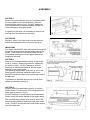
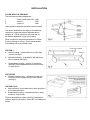
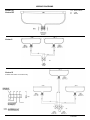
Installation and Operating Instructions
8/18149/0
Quartzray Vector Range
Models Covered:
Model
Vector I
Vector II
Vector III
Vector IRP
IMPORTANT
VR15
VR20
VR30
VR40
VR45
VR60
VR15RP
VR20RP
Heating Elements
1 x 1.5kW
1 x 2.0kW
2 x 1.5kW
2 x 2.0kW
3 x 1.5kW
3 x 2.0kW
1 x 1.5kW
1 x 2.0kW
Voltage
Weight
230-240V
230-240V
230-240V
230-240V
230-240V/400-415V
230-240V/400-415V
230-240V
230-240V
2.2kg
2.2kg
4.0kg
4.0kg
5.8kg
5.8kg
2.2kg
2.2kg
These instructions should be read and carefully retained by the user.
The installation of these appliances must always be carried out by a competent
electrician and be in accordance with the current IEE wiring regulations and
relevant Building Regulations.
The radiated heat from the heater is considerable and must be taken into
account when siting the heater. Ensure that the heater is not used in close
proximity to the skin or eyes.
Always isolate the heater from the supply before undertaking any maintenance
work of the appliance.
The Vector range of heaters are designed for internal use only. They are not
rated as flame-proof and must not be used when flammable dusts, gases, or
vapours, etc., are likely to be present in the atmosphere. If in doubt, advice
should be sought from the Health and Safety Executive inspectors or local fire
officers.
Quartz lamps are extremely fragile and must be handled with extreme care at all
times. Avoid touching the surface of the quartz sleeve with bare fingers. If the
sleeve is accidentally touched remove the finger print with a soft cloth moistened
with methylated spirits.
As with any fragile fitting mounted above head height, care must be taken when
siting the heater to avoid locations where it may be subjected to knocks. In high
risk areas such as sports halls etc. extra guarding may be required to protect the
heater from flying objects.. If in doubt consult the heater manufacturer.
WARNING
THIS APPLIANCE MUST BE EAR THED. HEATERS MUST BE
MOUNTED OUT OF REACH FROM OVERHEAD WALKWAYS AND
OPENING WINDOWS. THE HEATER MUST BE SECURELY FIXED AS IT
WILL BE DANGEROUS IN THE EVENT OF ANY INSECURITY IN ITS
FIXINGS.
SPECIFICATIONS
The Quartzray Vector range is available in 1,2 and 3 lamp models with
outputs of 1.5kW, 2kW, 3.0kW, 4kW, 4.5kW, and 6kW respectively. The Vector
III lamp model is supplied as a dual voltage unit and is suitable for use on 230240V 1pH and 400-415V 3N supplies.
ASSEMBLY
VECTOR 1
Remove the front assembly (see fig.1) and disconnect
the lamp leads from the terminal block. Remove
knockout(s) as shown in fig.2. DO NOT attempt to
remove knockouts on assembled heater as this will
cause damage to the fragile lamps.
If a guard is to be fitted it is necessary to remove one
end cap from the heater front (see fig.3).
VECTOR RP
Similar to Vector 1 but rain cover must be removed
before front assembly can be removed (see fig 4).
IMPORTANT
The supply cable MUST enter the back box from below
on this rain-proof model to prevent water entering the
heater. If the heater is to be wall mounted the two
screws/nuts retaining the cover support bracket will
need to be removed.
VECTOR II
Remove two front assemblies (see fig.1) and centre
cover (3 screws). Remove knockout for cable entry
as shown in (fig.2). DO NOT attempt to remove
knockout on assembled heater as this will cause
damage to the fragile lamps.
The incoming supply cable must enter by one of the
three knockout positions inside the centre cover.
DO NOT use the two chain hook holes at each end of
the back box.
If guards are to be fitted remove one end cap from
each front assembly (see fig.3).
VECTOR III
Remove three front assemblies (see fig.1) and two
centre covers (3 screws each). Remove knockout for
cable entry as shown in (fig.2).
DO NOT attempt to remove knockout on assembled
heater as this will cause damage to the fragile lamps.
The incoming supply cable must enter by one of the
three knockout positions behind the right hand centre
cover. DO NOT use the two chain hook holes at each
end of the back box.
INSTALLATION
FLOOR WALLS & CEILINGS
The minimum mounting heights are: 1.
2.
3.
Vector I and Vector RP 1.8M
Vector II
2.5M
Vector III
3.0M
(Also applies to apposite wall when wall mounted)
The above dimensions also apply to the distance
required to a side wall when suspended and a
distance of 1.0M is required to any end wall for
all heaters regardless of type of mounting.
Allow a minimum space above heaters of 150mm
to any overhang or ceiling. Do not locate heater
immediately below any socket outlet.
VECTOR 1
a. Wall mounting – screw back box to wall using
2 holes (see fig.2).
b.
Bracket mounting – fit bracket to wall and back
Box to bracket (see fig.5).
c.
Suspended mounting – remove 2 knockouts
(see fig.2) and suspend back box using conduit
or chain hooks.
VECTOR RP
a. Bracket mounting only – fit bracket to wall and
back box (cover support fitted) to wall bracket
(see fig.5).
VECTOR II & III
a. Wall mounting – screw back box to wall using the 2
or 3 holes provided.
b. Suspended mounting – suspend back box using
conduit or chain hooks.
Fit front assemblies to heater (see fig.7) and adjust
reflector angle to suit and on Vector RP, re-fit rainproof
heater.
IMPORTANT
When deciding upon the best location, consideration must be given to the
following requirements.
a. Avoid structures liable to vibration, e.g. crane gantries, which could
otherwise adversely affect lamp life.
b. The lamps are designed to operate within 5° of the horizontal plane. It is
very important to ensure that the heater is mounted horizontally, otherwise
the operating life of the lamp could be impaired.
c. Ensure appliance is mounted the correct way up so that it can be tilted
down but not up.
d. WARNING – THESE HEATERS ARE DESIGNED TO BE WALL
MOUNTED, BRACKET MOUNTED, OR SUSPENDED MOUNTED –
THEY MUST NOT BE CEILING MOUNTED. THEY MUST NOT BE
MOUNTED IN A ROOM CONTAINING A BATH OR SHOWER. DO NOT
MOUNT HEATERS CLOSER THAN 3.5 METRES FROM CURTAINS OR
SIMILAR SOFT FURNISHINGS.
ELECTRICAL
SUPPLIES
Wiring to the heater must be installed in compliance with the requirement of
the IEE Regulations and any local or insurance regulations.
All heaters are suitable for use on 230-240V single phase supplies. The
Vector III model is supplied as a dual voltage unit and is suitable for use on
400-415V three phase supply.
Wiring between the heater and the spur outlet or isolation switch must be in a
heat resisting cable with a temperature rating of T150. Sufficient slack cable
must be left to allow for angular adjustment of the heater body.
An all-pole isolating switch with a minimum separation of 3mm in each pole
must be fitted adjacent to the heater to facilitate local isolation.
If miniature circuit breakers are to be used to avoid ‘nuisance tripping’ due to
the high in rush at switch on, a type 3MCB with a tripping coefficient of 7-10
times rated current should be used. Any other switching device should be
Tungsten lamp load rated.
The Vector III heater must be connected in accordance with the instructions
inside the terminal cover lid. When connecting to 400-415V three phase
supplies the links must be removed from the terminal block. When the heater
is on a 230-240V supply, the ‘Danger 400-415V’ notice should be removed
from the terminal cover.
Always ensure that the cable grip is tightened.
IMPORTANT
Ensure the electrical supply cable is routed and restrained to prevent contact
with the external surfaces of the heater and is not positioned in the direct heat
beam.
When heater is close to a ceiling the reflectors must be rotated to avoid the
heat beam from directly overheating it. The reflector must point down at more
than 30° from the horizontal.
Vector I and RP when bracket mounted close to an end wall (minimum of
1.0m) should have the heat beam parallel to or angled away from the wall to
avoid overheating.
It is important that the user is instructed not to stack inflammable material in
the direct heat beam.
MAINTENANCE
Since the Vector Heater contains no moving parts little maintenance is
required beyond cleaning and lamp replacement. It is however essential that
the heater is not operated with accumulation of dust or dirt on the lamp(s) or
reflector(s) as this can cause a build up of heat and eventual damage . For
this reason the heater must be inspected regularly, depending upon
conditions and at least at yearly intervals.
Before undertaking any maintenance work on the heater due attention must
be paid to the following,
1. Always disconnect the heater from the electricity supply before attempting
to work on or near it.
2. Always ensure a safe means of access using an access lower or properly
supported ladder.
3. Some types of quartz lamps run with an internal pressure in excess of
atmospheric and while construction is very strong there is a slight risk of
shattering. If it is necessary to examine a bare lamp whilst in operation
then a protective screen must be used.
4. Allow adequate time for the lamps and body casing to cool before
attempting to work on the heater.
INSPECTION AND
CLEANING
1.
Check that all the lamps are functioning. If any thermostatic or time
controls are fitted ensure that the supply is ‘on’ before checking lamps.
Any failed lamps should be replaced (see lamp replacement). Remove
any accumulated dirt and check wiring and connections.
2.
Clean the lamp(s) and reflector(s) using a mild detergent solution and
soft cloth. Do not use any abrasive or caustic cleaners. Dry with a soft
cloth. Avoid touching either the quartz lamp sleeve or the aluminium
reflector with bare fingers. If they are accidentally touched remove any
finger prints using a soft cloth moistened with methylated spirit.
1.
Check that the lamp(s) are properly located in the spring retaining clips
and that they have not been disturbed by cleaning. The lamps should
be pushed fully back into the clips by applying light pressure on the end
caps only.
SAFETY IN OPERATION
The heater is operated by simply switching on the electrical supply, or, if
used in conjunction with a control system, then the supplier’s instructions
must be observed.
ALWAYS disconnect the heater from the supply before attempting to work
on or near it.
NEVER operate the heater with a high accumulation of dust or dirt on the
lamp(s) or reflector or with a damaged or corroded reflector.
NEVER use the heater where flammable dusts, gases or vapours, etc., are
likely to be present in the atmosphere.
NEVER operate the heater in close proximity to the skin or eyes.
NEVER allow materials which could be damaged or ignited by the radiated
heat to be placed in close proximity to the heater.
NEVER cover the heater – even when it is switched off.
ALWAYS refer to these instructions before attempting to dismantle the
heater.
AFTER SALES SERVICE
Your Quartzray Vector Heater is guaranteed from one year from date of
purchase. We undertake to exchange or repair free of charge within this
period, any part found to be defective due to a manufacturing fault.
Should you require after sales service, please get in touch with the supplier
through whom you purchased the appliance.
Please do not initially return a faulty appliance or part of an appliance to us
as this may result in transit damage and/or delay in providing service. Let
us know your difficulty quoting the model number and series letter of the
appliance. We will then take the appropriate action.
WIRING DIAGRAMS
Vector I &
Vector RP
G.Y - Green Yellow
R - Red
B - Black
Vector II
Vector III
3 Phase connection on Vector III only.
8/18149/0