1
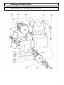
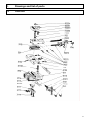
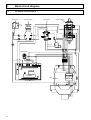
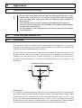
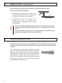
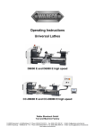
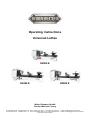
Operating instructions Universal Lathes D2000 E D2400 E D3000 E Walter Blombach GmbH Tool and Machine Factory D-42899 Remscheid Am Blaffertsberg 13 Phone: 0049 (2191) 597-0 Fax: 0049 (2191) 597-40 D-54673 Neuerburg WABECO Str. 1-10 Phone: 0049 (6564) 9697-0 Fax: 0049 (6564) 9697-25 www.wabeco-remscheid.de E-Mail: [email protected] E-Mail: [email protected] Index 2 EC-Conformity Declaration 4 1. 1.1 1.2 1.3 Product range Universal Lathe D2000 E Universal Lathe D2400 E Universal Lathe D3000 E 6 6 7 8 2. 2.1 2.2 2.3 2.4 2.5 2.6 2.7 2.8 Drawings and list of parts Headstock Support with motor and cover for D2400 E, D3000 E Leading spindle drive for D2000 E, D2400 E Leading spindle drive for D3000 E Antrieb mit Vorgelege zu D2000 W Cross table Tailstock Rear support with guide rods 9 9 10 12 14 16 18 20 21 3. 3.1 3.2 Circuit diagram Circuit diagram for D2000 E, D2400 E Circuit diagram for D3000 E 22 22 23 4. Delivery and installation 24 5. Starting-up and maintenance 25 6. Overload protection 25 7. Safety devices and recommendations 26 8. 8.1 8.2 8.3 8.4 8.5 8.6 8.7 8.8 Startup and Maintenance Electrical equipment Startup Maintenance Lubrication Initial cleaning of the machine Spindle head Compound rest Tailstock 27 27 27 28 29 29 30 31 29 9. 9.1 9.1.1 9.1.2 9.1.3 9.2 Speed regulation Speed election Speed setting for working with aluminium Speed setting for working with steel Speed setting for working with Brass, Copper Changing of speed 32 32 32 32 33 33 10. 10.1 10.2 Applications Longitudinal and transverse turning Thread cutting and automatic feed 34 34 35 Index 10.2.1 10.2.2 10.2.3 10.2.4 General note Application of change gears Altering the feeds or thread pitches Changing of feeds or thread pitche D3000 E 36 36 37 39 11. Pair of toothed wheels for left-hand thread 40 12. Angle plate with milling table 41 13. Three jaw-chuck and four jaw-chuck 42 14. Tool holder with conical sleeve 42 15. Steady and follow rest 43 16. Square turret head 43 17. Hand tool rest for turning wood 44 18. Wood turning lathe centre 44 19. Unit for lubrication coolant 45 20. Declaration of noise levels in accordance with DIN EN 24871 (German Industrial Standard) 46 21. Disposal of the lathe 46 3 EC – Conformity Declaration In the name of the manufacturer Walter Blombach GmbH Tool and Machine Factory based in Remscheid and Neuerburg D-42871 Remscheid D-54673 Neuerburg Postfach 12 01 61 WABECO Str. 1-10 Phone: 0049 (2191) 597-0 Phone: 0049 (6564) 9697-0 Fax: 0049 (2191) 597-40 Fax: 0049 (6564) 9697-25 We hereby declare that the universal milling and drilling machines specified below Universal Lathes Typ: D2000E – D2400 E – D3000 E meet the following regulation requirements for standard serie production - EC directive for machines EWG 91/68 and 89/392 EC low voltage directive 73/23/EWG In order to meet / implement the requirements of the above mentioned directives, the following applicable and previously published standards have been adhered to: EN 292-1 EN 292-2 EN292-2 Enclosure I EN 294 EN 349 EN 418 EN 60204 D-54673 Neuerburg ________________________________ City Signature 4 Outlay Dear customer! Congratulations on choosing the WABECO Universal Lathe. We have taken great care in its manufacture and we have given it a thorough quality control test. These operating instructions are to help you to work with it safely and properly. After unpacking the machine please check to see if any kind of damage has occurred during transportation. Any complaints must be made immediately. Complaints made at a later date cannot be accepted. If you have any questions or need any spare parts, please quote the machine number located on the front of the motor. Wir können Ihnen wahlweise unsere Bedienungsanleitungen und Prospekte in englischer und französischer Sprache kostenlos zusenden. We are able to send you free of charge our Operating Instructions and leaflets in French and/or English translation. Nous avons la possibilité de vous donner nos Instructions de Service et prospectus aussi en traduction francaise et/ou anglaise, sans frais. 5 1. Technical Data 1.1 Universal Lathe D2000 E Working range Centre distance .......................................................... Centre height.............................................................. Work spindle Power ......................................................................... Spindle speed infinetely variable................................ Spindle bore ............................................................... Taper in spindle nose................................................. Cross table diameter of chuck work above cross slide rest .......... Travel of cross slide ................................................... Travel of longitudinal slide Swivel range of the upper slide rest........................... Height of turning tools max. ....................................... Guideways Longitudinal support................................................... Cross support ................................................................ Stripping rings ............................................................... Length of guides............................................................ Width of guides.............................................................. diameter of chuck work, measured above the guiding bars ............................................................................... Tail stock Tail spindle´s range of displacement ............................ Tail spindle´s hole bore ................................................. lateral displacement of the tailstock to both sides ........ Advance Automatic advance........................................................ Screw cutting attachment - optional - metric thread ........................................................... - inch thread .............................................................. Noise values according DIN 45635 - part 1 Emission data: no-load running load running 350 mm 110 mm 1,4 kW, 230 V, 50 Hz 30 – 2300 r.p.m. 20 mm optional 30 mm MT3 – only for spindle bore 20 mm 126 mm 110 mm 58 mm 360° 20 mm ground guiding bars adjustable dovetail guide protection of the guides 575 mm 130 mm 220 mm 65 mm cone2 ±10 mm 0,085mm/r.p.m. optional 0,16 0,4 - 4,0 mm 10 - 32 thread per inch (TPI) LpA = 63 dB(A) LpA = 67 dB(A) - Subject to technical alterations - 6 1. Technical Data 1.2 Universal Lathe D2400 E Working range Centre distance ............................................................. Centre height................................................................. Work spindle Main drive...................................................................... Power ............................................................................ Spindle speed infinetely variable................................... Spindle bore .................................................................. Taper in spindle nose................................................. Cross table diameter of chuck work above cross slide rest ............. cross table range of displacement ................................ turning carriage´s range of displacement...................... swivel-feature of the upper slide rest ............................ Height of turning tools max. .......................................... Guideways Longitudinal support...................................................... Cross support ................................................................ Stripping rings ............................................................... Length of guides............................................................ Width of guides.............................................................. Ø of guides .................................................................... diameter of chuck work, measured above the guiding bars ............................................................................... Tailstock Tail spindle´s range of displacement ............................ Tail spindle´s hole bore ................................................. lateral displacement of the tailstock to both sides ........ Advance Automatic feed .............................................................. Screw-cutting attachment Optional - metric thread ........................................................... - inch thread .............................................................. Noise values according DIN 45635 - part 1 Emission data: no-load running load running 500 mm 110 mm electronic adjustable motor 1,4 Kw, 230V, 50 Hz 30 – 2300 r.p.m. 20 mm optional 30 mm MT3 – only for spindle bore 20 mm 126 mm 110 mm 58 mm 360° 20 mm ground guiding bars adjustable dovetail guide protection of the guides 740 mm 130 mm 30 mm 220 mm 65 mm cone2 ±10 mm 0,085 mm/r.p.m. Optional 0,16 0,4 - 4,0 mm 10 - 32 thread per inch (TPI) LpA = 63 dB(A) LpA = 67 dB(A) - Subject to technical alterations - 7 1. Technical Data 1.3 Universal Lathe D3000 E Working range Centre distance ............................................................. Centre height................................................................. Work spindle Main drive...................................................................... Power ............................................................................ Spindle speed infinetely variable................................... Spindle bore .................................................................. Taper in spindle nose................................................. Advance Automatic advance........................................................ Cross table diameter of chuck work above cross slide rest ............. cross table range of displacement ................................ turning carriage´s range of displacement...................... swivel-feature of the upper slide rest ............................ Height of turning tools max. .......................................... Guideways Longitudinal support...................................................... Cross support ................................................................ Stripping rings ............................................................... Length of guides............................................................ Width of guides.............................................................. Ø of guides .................................................................... diameter of chuck work, measured above the guiding bars ............................................................................... Tailstock Tail spindle´s range of displacement ............................ Tail spindle´s hole bore ................................................. lateral displacement of the tailstock to both sides ........ Advance Automatic advance........................................................ 500 mm 110 mm electronic adjustable motor 1,4 Kw, 230V, 50 Hz 30 - 2300 r.p.m. 20 mm Optional 30 mm MT3 – only for spindle bore 20 mm 0 - 250 126 mm 100 mm 58 mm 360° 20 mm ground guiding bars adjustable dovetail guide protection of the guides 740 mm 130 mm 30 mm 220 mm 65 mm cone2 ±10 mm 0-250 mm/min Screw cutting attachment metric thread .......................................................................... 0,4 - 3,0 mm inch thread.............................................................................. 10 - 32 thread per inch Noise values according DIN 45635 - part 1 Emission data: no-load running load running LpA = 63 dB(A) LpA = 67 dB(A) - Subject to technical alterations - 8 2. Drawings and list of parts 2.1 Headstock for D2000 E, D2400 E and D3000 E Part-No. Order-No. Designation 11 1124 1128 111 1118 11181 11121 1115 1116 11141 1114 1113 1112 1112 1111 128 1281 1282 1283 1284 1285 1286 1287 1288 1289 1290 10200011 10201124 10201128 10200111 10201118 10211181 10211121 10201115 10201116 10211141 10201114 10201113 10101112 10201112 10201111 10200128 10201281 10201282 10201283 10201284 10201285 10201286 10201287 10201288 10201289 10201290 Headstock Bronze bushing Bronze bushing Spindle with flange Bearing cap Hexagon socket screw Feather key Spacer sleeve Tapered roller bearing Starter pulley Toothed belt pulley Spacer sleeve Belt pulley for Universal Lathe D2000 Belt pulley for Universal Lathe D2400 E Regulating nut Plexiglass cover Adjusting ring Shaft Eccentric Stop Bracket Angle piece Hexagon bolt with nut Pressure spring Lock washer Pin 9 2. Drawings and list of parts 2.2 Support with motor and protective cover for D2400 E and D3000 E 10 Part-No. Order-No. Designation 125 1251 1252 1253 1254 1255 1256 1260 1258 1257 1259 10200125 10201251 10201252 10201253 10201254 10201255 10201256 10201260 10201258 10201257 10201259 10201200 Cover Stud bolt + radial nut Support Potentiometer Master switch with undervoltage release Switch right/left Motor Limit switch, protective cover Circuit board Motor cover Screws Collecting reservoir for chips 2. Drawings and list of parts 2.2 Support with motor and protective cover for D2400 E and D3000 E 11 2. Drawings and list of parts 2.3 Leading spindle drive for D2000 E and D2400 E Part-No. Order-No. Designation 1119 1145 1146 1147 1149 11491 1261 126111 12611 126112 126113 126114 126115 126118 126116 126117 12612 112 11212 11213 11214 1122 1123 1125 1126 1127 1131 11311 11315 114 1141 11411 11215 114114 1142 1143 114816 114818 114820 114822 114824 114828 114832 114834 114836 114840 10201119 10201145 10201146 10201147 10201149 10211491 10201261 102126111 10212611 102126112 102126113 102126114 102126115 102126118 102126116 102126117 10212612 10200112 10211212 10211213 10211214 10201122 10201123 10201125 10201126 10201127 10201131 10211311 10211315 10200114 10201141 10211411 10211215 102114114 10201142 10201143 102114816 102114818 102114820 102114822 102114824 102114828 102114832 102114834 102114836 102114840 10201100 Lubricating nipple Toothed belt Z 120 XL037 Toothed belt Z 140 XL037 Hexagon socket screw + washer Quadrant holder Hexagon socket screw + washer Clamping piece Feather key Axis Ball bearing Spacer sleeve Drive belt with belt pulley Drive belt with belt pulley Drive belt J 8-559 suitable for Universal Lathe D2400 E Washer Stop nut Spindle guide, complete Feed spindle Feather key Bushing Toothed belt pulley Washer Nut Adjusting ring Pressure spring Coupling Eccentric shaft, complete Stud bolt + nut Ball bearing Change gear quadrant Hexagon bolt Bronze bushing Nut Toothed belt pulley Z 14 Washer Washer Change gear Z16 (without picture) optional Change gear Z18 (without picture) optional Change gear Z20 (without picture) optional Change gear Z22 (without picture) optional Change gear Z24 (without picture) optional Change gear Z28 (without picture) optional Change gear Z32 (without picture) optional Change gear Z34 (without picture) optional Change gear Z36 (without picture) optional Change gear Z40 (without picture) optional Belt set compl. 5 pieces for Lathe D2400 E consists of: Part-No. 1145 (2x) Part-No. 1146 (1x) Part-No. 126118 (2x) Change gears 1 set 10 pieces Z16 - Z40 10201101 12 2. Drawings and list of parts 2.3 Leading spindle drive for D2000 E and D2400 E 13 2. Drawings and list of parts 2.4 Leading spindle drive for D3000 E 14 Part-No. Order-No. Designation 1 2 3 4 5 6 7 8 9 10 11 12 13 14 15 16 17 18 19 20 21 10300001 10300002 10300003 10300004 10300005 10300006 10300007 10300008 10300009 10300010 10300011 10300012 10300013 10300014 10300015 10300016 10300017 10300018 10300019 10300020 10300021 D.c. Motor Toothed belt Toothed belt pulley Motor bearing 3 screws Bracket 2 scres 2 adjusting nuts Pressure ring Bushing 2 thrust bearing Run-on-ring 2 screws Needle bearing Distance ring Needle bearing Toothed belt pulley Clutch disk Handle Operating pin Threadcutting coupling 2. Drawings and list of parts 2.4 Leading spindle drive for D3000 E 1 21 20 2 3 4 5 19 18 6 17 16 15 7 14 13 12 11 10 9 8 15 2. Drawings and list of parts 2.5 Leading spindel drive with gear motor for D2000 E 16 Part-No. Order-No. Designation 1152 119 119 11912 116 1161 11471 114114 11823 11914 11911 1173 11811 11712 1171 1128 11722 11721 1181 11824 11822 182 11821 11825 10101152 10100119 10101120 10111912 10100116 10101161 10111471 102114114 10111823 10111914 10111911 10101173 10111811 10111712 10101171 10101128 10111722 10111721 10101181 10111824 10111822 10100182 10111821 10111825 Support with A.C. motor with rotary current motor Bearing plate Mounting support of quadrant Hexagon socket screw Washer Toothed belt pulley Z 14 Toothed belt Drive belt J 610 Screw with washer Bearing plate Nut and washer Adjusting rod Axle Ball bearing Roller Retaining ring Axle Retaining ring Toothed belt pulley Belt pulley Feather key Retaining ring 2. Drawings and list of parts 2.5 Leading spindle drive with gear motor for D2000 E 17 2. Drawings and list of parts 2.6 Cross table Part-No. Order No. Designation 311 3111 31111 31112 3112 3113 31131 3114 3115 312 3121 31211 31212 1141 3122 3124 3125 321 322 3221 32211 32212 3222 3223 32231 32232 32233 32234 10200311 10203111 10231111 10231112 10203112 10203113 10231131 10203114 10203115 10200312 10203121 10231211 10231212 102W1141 10203122 10203124 10203125 10200321 10200322 10203221 10232211 10232212 10203222 10203223 10232231 10232232 10232233 10232234 10200300 Lower part of cross slide Nut holder Bolts + washers Bronze nut Bronze nut Shim Clamping bolt Wiper ring Lubricating nipple Upper part of cross-slide Spindle bearing compl. with graduated ring Spindle Ball-ended crank Hexagon socket Threaded pin + plain nut Threaded pin with thrust piece Readjusting gib Lower part of turning carriage Upper part of turning carriage Spindle bearing compl. with graduated ring Spindle for turning carriage Ball-ended crank Readjusting gib Stud bolt Clamping plate Hexagon bolt Pressure spring Thick nut Longitudinal support compl. Parts-No. 321 - 3112 - 3122 - 32211 - 32212 - 1141 - 3221 - 3222 - 322 - 3223 - 32232 - 32233 - 32231 - 32234 Transversal support compl. Parts-No. 3124 - 31131 - 3112 - 3114 - 3115 - 31112 - 3111 - 31111 3122 - 312 - 3125 - 311 - 3113 - 31211 - 3121 - 31212 - 1141 Cross table compl Spindle compl. with transversal support Parts-No. 3121 - 31212 – 31211 Spindle compl. with longitudinal support Parts-No. 3221 - 32211 – 32212 10200301 10200302 10200303 10200304 18 2. Drawings and list of parts 2.6 Cross table 19 2. Drawings and list of parts 2.7 Tailstock 20 Part-No. Order-No. Designation 41 411 412 414 415 42 421 422 1151 423 4231 4234 4233 31212 424 4251 42511 4141 4252 119 10200041 10200411 10200412 10200414 10200415 10200042 10200421 10200422 10201151 10200423 10204231 10204234 10204233 10231212 10200424 10204251 10242511 10204141 10204252 10200119 10200400 Lower part of tailstock Shim Capstan with stud bolt Washer Hexagon nut Upper part of tailstock Quill Flange Hexagon socket screw Spindle Adjusting ring Spring washer Washer Ball-ended crank Hexagon bolt with washer Capstan with clamping bolt Insert Insert Feather key Lubricating nipple Tailstock compl. without lathe center 2 Drawings and list of parts 2.8 Rear support with guide rods Part-No. 5 51 52 522 523 31212 4231 524 53 531 4232 4233 533 541 542 543 544 Order-No. 10200005 10200051 10200052 10200522 10200523 10231212 102H4231 10200524 10200053 10200531 10204232 10204233 10200533 10200541 10200542 10200543 10200544 10200500 Designation Rear support (only the cast iron part) Guide rods Feed spindle Washer Axial needle bearing Ball-ended crank Spacer sleeve Bronze bushing Protective channel Screw + washer Graduated ring Retaining ring Lubricating ring Hexagon bolt Washer Serrated lock washer Hexagon nut Rear bearing compl. 21 3. Block circuit diagram 3.1 for D2000 E and D2400 E mains plug emergency OFF main switch switch for protection cap potentiometer Date Danger motor control electronics 22 reversing switch mains plug feed motor transformer control electronics rectifier capacitor reversing potentiometer for D3000 E motor reversing switch 3.2 control electronics Switch for Protection cap main switch Block circuit diagram potentiometer emergency OFF 3. 23 4. Delivery and installation The lathes are carefully packed in our factory. Please check the following on delivery: 1. whether the packaging has been damaged and/or: 2. whether the lathes shows signs of transport damage or if there are grounds for complaint. In this case we request your immediate notification. Claims made at a later date cannot be acknowledged. The lathe must be installed on an appropriate, level and firm base. This would be, for example: a base cabinet such as in our accessories programme own work bench as long as it is strong enough to carry the weight of the machine without warping (see technical data and check with spirit level) and has an even surface. a steel plate The lathe must be firmly screwed down onto the base. To facilitate this, there are 9 mm holes in the machine base. Good results and a minimum of vibration during operation can only be guaranteed if the above mentioned requirements for secure mounting have been kept to. The installation of the machine should take place where there is sufficient lighting, electrical cables with earthed sockets and O-conductors are installed adequately near to the machine so that the mains connection lead is not subject to any tension whatsoever. The mains lead should be such that, by means of a multiple socket, a coolant or lubrication unit can also be connected. 24 5. Starting-up and maintenance i 6. Fix the machine on a sturdy, level support Use sharp processing tools Adjust speed setting and feed to fit the material and diameter of the tool Clamp the tools so that the clamping position is as near possible to the workpiece Clamp the workpieces fast and without vibrations. Long pces. support with tailstock or with fixed stay. Apply coolant and lubricant for better surface quality (finish) and dimensional accuracy Fix processing tools and workpieces on clean clamping surfaces Grease the machine sufficiently Use the correct tools for removing the material from the workpieces Set correct bearing clearances and align guides early enough Overload protection i Wait approx. 1 second after switching off the machine manually or after an automatic switchdown following an overload before you switch on again. This will ensure that the motor is protected effectively in all work situations. Otherwise it is possible that the machine will not come on because the relay for the electronics has not been able to function. 25 7. Safety Instructions 1. 2. 3. 4. 5. 6. 7. 8. 9. 10. 11. 12. 13. 14. 15. 16. 17. The feed line for the motor may only be connected to a shock-proof socket or junction box. (Have the socket or junction box checked by an electrician beforehand; protection against children being able to put into operation). The socket or junction box must be close enough to the equipment, that the current-carrying cable is subjected to no tensile strain whatsoever. The three-phase A.C. motor must be connected by an electrician over a protective switch of 1 ampere to the 380 V mains supply. When maintenance or cleaning work is being done, the machine must be shutdown and the mains plug pulled out. Do not brake workpieces or chuck by hand or any other objects. Wear safety goggles when working the machine. Do not remove the chips with the hand. Use corresponding aids (hand brush, hook, paint brush). Always keep the protective hood on the driving mechanism closed. The turning tools must be firmly tightened at the correct height and as short as possible. The turning tools must never be exchanged when the machine is running. Never leave the clamping chuck key in (even when not in operation). Observe the bearing distance of the turning chuck. (Turning jaws max. 40mm ∅, Drilling jaws max. 100mm ∅). Never take measurements on work pieces being turned (danger of accidents and damage to the measuring gauges) Do not wear loose items of clothing (ties, shirt sleeves, jewellery etc.). When working between centres, always centre well in order to avoid a flying-out of the workpiece. In addition, check the tightening screw of the tailstock to make sure it is tight. When working with automatic advance take care that the cross table does not touch the chuck or the tailstock. Never leave the machine when in operation. When turning wood, use the lathe centre fort he slaving of the work piece instead of the lathe chuck. 18. The machine must be secured so that it cannot be swichted on by children. Make sure that other people do not come in contact with the machine. 19. The machine must be kept dry at all times. 20. Check the machine frequently for damage. Any damage parts must be replaced with original parts and should be fitted by an expert or by us. 26 8. Startup and Maintenance 8.1 Electrical equipment The lathes are fitted with a master switch with undervoltage release, i.e. this switch must be switched on before the machine can be switched on via the reserving switch. The master switch must also be switched on again following a power failure. ON - OFF lever for automatic feed NOT VORW 0 RUECKW AUS potentiometer NOT-AUS switch right - left master switch i All lathes can only switched on with closed plexiglass bonnet. If you want to change the turning direction through the switch right-left the switch must stay for 1 sec. on 0-position for the reason that the relay of the potentiometer has enough time to react. 8.2 Start up i 8.3 Prior its putting into operation the machine must once more be cleaned with great care. All lubricating points have to be furnished with grease while the cross slide, the threaded spindles, the guide bars and the quill are thoroughly oiled. Turn by hand all spindles in order to check for their smooth turning. Run in the lathe with the lowest possible rotary speed being switched on. A full load to start with must be avoided! Maintenance The longtime serviceability is vitally dependent upon a corresponding serving attendance. The lathe needs to be cleaned after every turning job. i In case the lathe is being erected within a moist cellar, all naked parts need to be oiled after completed usage to avoid corrision. An overall and constant lubrication of all moving parts is highly signeficant. In case backlash within the bearings or within the guideways of the slides should occur, readjust in time to avoid the bearing or the guideways of the slides being destroyed. 27 8. Startup and Maintenance 8.4 Lubrication Prior to every putting into operation all lubricating points of the lathe must receive a grease for roller bearings having commercial quality. Both guiding bars have to be greased, too, preceding every putting into operation. The two dovetail guides of the cross slide, the threaded spindles of the cross slide accessible from below, the feed rod as well as the tailstock quill have to be greased at intervals of 100 service tours each using lubricating oil. When greasing make sure to put the slide of the cross slide to its hindmost position while extending the tailstock quill to its foremost posision. Greasing the tailstock spindle is performed via the hollow borehole within the quill. apply engine oil prior to every putting into operation NOT VORW 0 RUECKW AUS apply grease prior to every putting into operation apply grease prior to every putting into operation 28 8. Startup and Maintenance 8.5 Initial cleaning of the machine Prior to putting the machine into operation for the first time all maked parts have to be cleaned applying petroleum or gasoline used for cleaning, because these parts have been treated with slushing oil before leaving the factory. 8.6 Spindle head The spindle head is firmly attached to the slide bars. In the spindle head, the work spindle is run on two adjustable precision tapered roller bearings. adjustment nut ON -OFF lever for automatic feed Should a readjustment of the bearings be neccessary, please proceed in the following manner: 1. Loosen the locking screw in the adjustment nut. The adjustment nut is located at the rear end of the work spindle. 2. Turn the adjustment nut in a clockwise direction until the bearings again run free of play (the work spindle being easily able to be turned by hand). 3. Tighten the locking screw again. i Roller bearing adjusted too tightly become useless after a short period Automatic feed: Likewise, the is an on-off lever for the automatic forward feed on the front side of the spindle head. When supplied the wheels for the forward feed 0.085 mm/rev. are attached. 29 8. Startup and Maintenance 8.7 Compound rest The compound rest consists of a longitudinal and a transverse slide rest. Its dovetail guides are ajustable. hexagon socket screw for tightening the compound rest take-up screw + counter nuts longitudinal slide take-up screw + counter nuts transverse 8.7 Compound rest Should a readjustment be necessary, please proceed in the following manner: 1. Counter nuts must be loosened. 2. By using a socket head wrench, tighten the readjustment screws until the carriage can just be turned to and from by means of the crank. 3. adjustment tighten the counter nuts again. Longitudinal slide: The longitudinal slide rest is mounted on the transverse slide rest and can be pivoted through 360° degrees. Thus, it is suitable for the turning of tapers. For adjustment, the 4 mm Allen key is used to loosen the two screws located on the outer sides of the transverse slide rest. The arrow on the transverse slide rest. There is a scale of the degrees on the longitudinal slide rest. The distance between two graduation marks represents one degree. Scale rings: To set the turning tools, the slide rest spindles have graduation collars with graduation marks. One graduation mark represents a 0.05 mm feed adjustment which corresponds to a 0.1 mm chip removal on the work piece. The hexagon socket screw is provided for cases where the compound rest is to be fixed to the slide bars (e.g. in the case of transverse turning.) It screws down the clamped piece at the lower side of the transverse slide rest against the two slide bars. 30 8. Startup and Maintenance 8.8 Tailstock The tailstock is attached to the slide bars in such a way that it is slidable. It can be easily tightened in any position by screwing the lower T-handle (4251). It can be separated into barrel and base. By loosening the spanner bolt (424), the tailstock barrel can be pushed to either side by up to 10 mm and is, therefore, suitable for the turning of slight tapers. After completing the taper work, the tailstock is to be returned to its original position. The central position of the tailstock is indicated by the mark on the side. By making a trial turning operation establish whether the working piece is cylindrical and if necessary correct the position of the tailstock. Solid tailstock sleeve: The solid tailstock sleeve, which is provided with a millimetre scale, is designed in such a way that the lathe centre, drill barrel or chuck are automatically ejected when turning back. Tool clamping: An inner cone MT 2 which is worked into the tailstock sleeve serves to accept the tools. By screwing the upper T-handle (4251), the tailstock sleeve can easily be clamped in any position. The tailstock sleeve can be moved axialy over a threaded spindle by using the crank (31212) located at the rear end. T-handle (4251) for tightening the tailstock crank (31212) to move the tailstock sleeve spanner bolt (424) T-handle (4251) for tightening the tailstock 31 9. Speed regulation 9.1 Speed selection The spindle speed is to be selected according to the type of material and the diameter of the work piece: Small diameter Large diameter ⇒ ⇒ relatively high speed low speed The cutting speed is the result of speed and diameter. With a known and required cutting speed, the necessary spindle speed can be calculated in the following way: cutting speed (V) x 1000 speed (n) = diameter of workpiece (d) x 3,14 Example: An aluminium workpiece which has a diameter of 20 mm is to be turned with a cutting speed of 100 m/min. 100 x 1.000 100.000 = 20 x 3,14 62,8 = 1592 1/min Now, from those speeds available, the one is selected which is nearest to the ideal speed of 1592 1/min. (in our case 1600 1/min.). 9.1.1 9.1.2 32 Speed Setting for Working with Aluminium workpiece- Ø approx. r.p.m. cutting speed m/min 10 mm 2300 75 20 mm 1600 100 40 mm 800 100 60 mm 530 100 80 mm 400 100 100 mm 320 100 Speed setting for working with steel workpiece- Ø approx. r.p.m. cutting speed m/min 10 mm 1600 50 20 mm 800 50 40 mm 400 50 60 mm 270 50 80 mm 200 50 100 mm 160 50 9. Speed regulation 9.1.3 Speed Setting for Working with Brass, Copper 9.2 workpiece- Ø approx. r.p.m.. cutting speed m/min 10 mm 2300 80 20 mm 1270 80 40 mm 640 80 60 mm 425 80 80 mm 320 80 100 mm 250 80 Changing of speed Rotational speed 45 - 2300 min-1: The rotational speed of the work spindle can be infiniely varied between 45 and 400 rpm in the 1. Step or in the 2. Step between 200-2300 rpm. using the potentiometer on the front of the machine. speed setting at the potentiometer 1. step r.p.m. 2. step r.p.m. 10 45 200 20 105 350 30 175 740 40 260 1050 50 325 1440 60 360 1650 70 400 1860 80 460 2120 90 490 2160 100 500 2300 Rotational speed 45 - 400 rpm: The drive belt must be relocated if the lower speed stage with a minimum speed of 45 rpm is required. Proceed as follows: Remove the protective cover and release the drive belt by unscrewing the clamping nut and turning the star handle clockwise until the drive belt can be relocated. Then re-tighten the drive belt in the reverse sequence of steps. rotational speed 45-400 rpm clamping nut star handle potentiometer 33 10. Applications 10.1 Longitudinal and transverse turning Longitudinal turning: In the case of longitudinal turning tool moves parallel to the axis of the workpiece. For roughing at longitudinal turning the use of either a straight or arcuated turning tool is favourably. Transverse turning: The tooling of the face is known as transverse turning. In the case of transverse turning, the turning tool is moved at 90 degrees to the turning axis of the piece being turned. In so doing the compound rest is to be locked. The main cutting edge of the turning tool is to be exactly centred so that no scar remains in the middle of the workpiece. The arcuated tool is used for transverse turning. 6 1 2 3 4 5 to 1+2: Roughing tools arcuated to the left and or right: By using them a maximum on material is to be cut off in as short a time as possible (without paying attention to the finish on the surface of the work piece). They can be used for longitudinal and transverse turning. 34 to 3: Offset side turning tool: Used for smoothing (clean surface) in the case of longitudinal and transverse turning. to 4: Outside thread turning tool: Used for cutting of outside threads. to 5: Narrow square-nose cutting tool: Used for the cutting of grooves and slicing of workpieces. i When inserting the slicing tool No. 5, pay careful attention to the exactness of the centre height of the turning tool. Work with low speed and cool the tool (use soluble oil or emulsion for cooling: serves to lubricate and for the removal of chips.) The slicing tool is to be clamped as short as possible and at 90° degrees to the workpiece. to 6: Right side tool: Used for the hollowing-out of boreholes. Clamp as short as possible in order to avoid ascillations of the turning tool which might otherwise occur (uneven surface). 10. Applications 10.1 Longitudinal and transverse turning i For the reason of the power at the turning chisel take care that the tool is short and fast fixed. If the lever arm is to long the turning chisel curves and springs back. The cutting part enters uneven into the workpiece and is producing a waved surface. Take care that the turning chisel is placed on the middle of the turning piece. The control of the height position of the middle of the workpiece is done with the live lathe center in the tailstock. For the regulation of the height position of the turning chisel use with straight sheet steel pieces. 10.2 Thread cutting and automatic feed 10.2.1 General note The tread turning chisel is a form turning chisel with the profile of the thread to be cut.. It is ground according to jigs (diagram 1) and must be adjusted exactly to the middle of the workpiece as, otherwise, the profile of the thread would be distorted. In order to obrain the correct position of the flanks of the thread to the axis of the workpiece, the grinding jig is put against the work piece and the turning tool is adjusted in accordance with it (diagram 1). For this purpose the jig is pushed successively on to both flanks of the turning tool. The feed of the thread turning tool is effected over the lead screw and must correspond to the thread pitch. Setting the thread turning chisel 90° Change gears: The connection between the feed gear mechanism and the lead screw is made by the translating gear wheels (extras at D2000, D2000E and D2400) included in the attachments. By setting various combinations of gears it is possible to cut a metric right-hand thread with a pitch of 0,4 mm - 3 mm and an inch-system right-hand thread with a pitch of 10Z/1" - 32 Z/1" (see table). (For left hand threads see the section "Gear pair, left-hand thread"). The various distances of the axes between the gears can be adjusted by swiveling the quadrant and readjusting the quadrant bolts. 35 10. Applications 10.2.1 General note Feed: The feed is switched on by means of the T-handle on the front side of the spindle head. i When cutting threads it must be remembered that the feed remains on throughout to ensure that the turning chisel always returns to the same positon when cutting more than one thread. For this reason, after completing the cut the turning chisel with the transverse carriage is cammed out as, otherwise, the flanks and cutting edges could be damaged and is returned to its original position by altering the turning direction of the motor over the reversing switch. It is advisable to make a 4-5 mm wide grove at the end of the thread in order to enable a better camming out of the threading tool. Long thread: In the case of long thread diameters, the revolving lathe centre should always be used in order to prevent the work piece from being pushed away. Overload clutch: To avoid damage at the advance system the main spindle and the leading spindle drive are connected with an overload clutch. 10.2.2 Application of change gears - optional for D2000 and D2400 E For the purpose of automatic longitudinal turning there are two feed rates, being at your disposal: 0,085 mm and 0,16 mm/revolution. (Upon delivery, the gears producing a feed of 0,085 mm/revolution have been put on). Putting on different combinations of gears enables you to cut metric thread ranging from 0,4 to 3,0 mm in pitch. The same applies to inch thread ranging from 10 threads/" to 32 threads/" in pitch. Table on thread cutting * = Extras 36 mm 0,4 0,5 0,7 0,75 0,8 1,0 1,25 1,5 1,75 2,0 2,5 3,0 A 48 48 48 48 48 48 48 48 48 48 48 48 B 16 20 14 18 16 14 20 36 28 40 40 48 C 40 40 20 24 20 14 16 24 16 20 16 16 Z/1" 10 11 12 13 14 16 18 19 20 24 28 32 A 34 34 34 34 34 34 34 34 34 34 34 34 B 36 36 36 36 36 36 14 34* 18 24 18 18 C 20 22 24 26* 28 32 14 36 20 32 28 32 10. Applications 10.2.2 Application of change gears - optional for D2000 and D2400 E Table automatic longitudinal feed for D2000 - D2400 E 10.2.3 mm/ 0,085 0,16 A1 48 48 A2 14 18 B1 48 48 B2 14 20 C 48 48 Altering the feeds or thread pitches for D2000 E and D2400 E When altering the feeds or thread pitches, proceed as follows: 1. a. b. c. d. e. f. g. Changing the feed from 0,085 mm to 0,16 mm Loosen the fixing screw D of the change gear quadrant. Loosen and remove the hexagonal nuts and washers from the bolts A and B. Loosen the hexagonal bolts A and B. Remove the toothed belt connecting A and B. Unscrew the bolt B together with the 2 tooth belt pulleys from the quadrant and remove it by slightly tilting upwards the bolt. This at the same time leaves free the toothed belt connecting the main spindle with A by placing the toothed belt onto the great driving pulley E. Remove both tooth belt pulleys Z 14 from their bolts A and B and change them for tooth belt pulley Z 18 or tooth belt pulley Z 20, respectively. Then, tighten bolt A. Mount and tighten the washers and nuts of A and B. Mount bolt B, together with both tooth belt pulleys into the change gear quadrant again by slightly tilting the bolt and screwing it into the square nut located behind the quadrant. Put on the toothed belt connecting B and C, pull bolt B upwards imparting tension to the toothed belt. Then, tighten bolt B. Put on toothed belt from main spindle to bolt A and from bolt A to bolt B. Then tense the belt between main spindle and bolt A by means of the change gear quadrant and tighten the change gear quadrant with fixing screw D. Close the cover of the headstock and tighten again the screw with hexagonal recessed hole. driving pulley E fixing screw D bolt A bolt B C 37 10. Applications 10.2.3 Altering the feeds or thread pitches for D2000 E and D2400 E 2. Changing the feed from 0,085 mm to a metric pitch of 1,5 mm a. - c. Start the procedure exactly as already described under pos. 1, a-c, expect for the hexagonal nut being removed as well from the shearing bushing C, as described under pos. 1 b. d. Pull off the bushing and the tooth belt Z 48 from the shearing bushing C. Put the bushing and the tooth belt pulley Z 24 onto the shearing bushing but, make sure that the bushing precedes the tooth belt pulley. Bolt B with toothed belt will not be needed with thread cutting! e. Pull off tooth belt pulley Z 14 from bolt A and put on tooth belt pulley Z 36. Put on toothed belt connecting the main spindle with bolt A and from A to C. f. - g. Proceed as described under pos. 1, f-g! Z 48 Z 14 bolt B escape Z 48 C Z 48 i 3. Only the two short toothed belts (1145) are required for cutting metric threads. The slightely longer toothed belt (1146), which connects the main spindle with wheel A The toothed belt (1145) connects wheel B with wheel C. Changing the feed from 0,085 mm to thread pitch 12 threads/" Proceed exactly as already described under pos. 2. The procedure differs merely in additionally changing the tooth belt pulley Z 48 running on bolt A for the tooth belt pulley Z 34. to change Z 48 against Z 34 bolt B escape i 38 As when cutting metric threads, only the two shorter toothed belts (1145) are normally required. Exeption: For a lead of 13. 14. 16 or 19 threads/inch. In this case, the longer toothed belt (1146) is required to connect wheels A and C. 10. Applications 10.2.4 Changing of feeds or thread pitch for D3000 E 1. Working with the automatic longitudinal feed a. Turn the handle (19) on the symbol longitudinal turning. For the connection of the clutch disk turn with with the handle (31212) a little. b. Switch-on the direction switch on the right of the substructure. middle position = off left injected = advance to the spindle right injected = advance to the tailstock With the potentiometer adjust the feed speed. c. After the automatic longitudinal turning but the direction switch on the middle position. 2. Working with the thread cutting unit a At first for the desired thread pitch the changing wheels must be mounted. Your receive the machine from our factory with yet mounted wheels Z 36 and Z 24 for a thread pitch of 1,5 mm. During putting of metric threads the toothed wheel Z 48 is placed on the change gear quadrant as shown on the picture 6.22. During cutting of inch thread this wheel has to be replaced through the tooth wheel Z 34. For the different thread pitches only the tooth wheels B (beside Z 48) and C ( on the main spindle) according to picture 6.22 have to been changed. b. Select slowest spindle feed. c. Turn the handle (19) on the symbol thread turning. The handle must be in function till the thread is ready produced. For the cutting of several cuts to produce the thread the machine must be stopped with the reversing switch at the end of the thread and at the same time the threadcutting tool separated. Now turn the reversing switch on left turning and the carriage runs in the direction of the tailstock. If the threadcutting tool is placed approx. 5 mm in front of the beginning of the thread, stop again the machine, turn the cross-slide ahead like the before made cut plus the desired removal of material. Then turn the reversing switch on right turning and execute the cutting of the thread. Only when the thread is finished the handle (19) can be put out again. handle (31212) handle (19) NOT VORW 0 RUECKW AUS potentiometer direction switch 39 11. Pair of toothed wheels for left-hand thread To cut left-hand threads, the toothed belt gear No. 11214 on bolt A is to be exchanged for the toothed gear Z 75 and the toothed belt gear No. 1114 on the work spindle exchanged for the toothed gear Z 50. To do this, proceed in the following manner: a. b. c. d. e f. g. h. i. j. k. Pull out the mains plug, loosen the hexagon socket screw at the front side of the headstock and open the cover. Remove the belt from the workspindle. Loosen the screw D of the quadrant. Loosen bolt A and B on the quadrant and remove toothed belt. Remove bolt A on the quadrant upwards and bolt B on the quadrant downwards. Loosen nut and washer from bolt A and remove. Loosen toothed belt gear No. 114114 and No. 11214 from bolt A and remove. Loosen the headless pin on the adjustment nut No. 1111 on the workspindle. Loosen the adjustment nut and remove from the workspindle. Remove the V-belt pulley No. 1112, the separator bush No. 1113 and the toothed belt gear No. 1114 from the workspindle. Mount the toothed belt from the workspindle and tighten firmly with the adjustment nut. Mount toothed gear Z 75 and the toothed belt pulley No. 114114 on to the bolt A and tighten with the washer and the hexagon nut. Mount toothed gear Z 50, separator bush No. 1113 and V-belt pulley No. 1112 on to the workspindle and tighten with the adjustment nut. Pay attention to the correct adjustment of the tapered roller bearings see section“headstock“ Lay the toothed belt from A to B, cam in the toothed gear Z 75 with Z 50 by swivelling the quadrant, tighten the screw D. Tense the toothed belt from A to B through removing B. Lay the drive belt on the workspindle and tense . Close the cover and tighten with the hexagon socket screw at the headstock. 1114 change against Z 50 1112 1111 D 11214 change against Z 75 bolt B 40 12. Angle plate with milling table for drilling and milling The milling is used to produce flat surfaces and grooves. When milling the advance and feed motion are effected with the angle plate from the workpiece. If the angle plate is correctly mounted on the compound rest (see assembly instructions), the workpiece can be rigidly and firmly attached to the clamping plate. This should be cleaned of dirt and chips beforehand in order to guarantee a good rest. The clamping screws used are inserted into the Tgroove of the clamping plate. In addition, a machine vice can be attached to the clamping plate. The tool is to be clamped as short as possible in the collet chuck (danger of breaking). If the tool is firmly clamped, the depth adjustment can be made over the feed shaft. Assembly of the angle plate with the milling table At first you remove the longitudinal slide rest from the transversal slide rest of the lathe. Then the angle is screwed on to the carriage of the transversal slide rest with the delivered hexagon screw. After removing the clamping plate and the spring from the longitudinal slide rest you fix the longitudinal slide rest as indicated against the clamping angle. 41 13. Three jaw-chuck and four jaw-chuck The three-jaw chuck serves to clamp circular, triangular and hexagonal workpieces centrically to the spindle axis. The four-jaw chuck serves to clamp square workpieces centrically to the spindle axis. i Danger of accident Do not try to clamp larger workpieces. The chucking power is then too low and the jaws can detach themselves. Mounting of turning jaws: The jaws and guides are numbered from 1-3. Open the chuck by means of the chuck key until the jaws loosen. (order: 3, 2, 1 bzw. 4, 3, 2, 1). Now, take the inner jaws beginning with the number 1 and put this in the guide number 1. Push the jaw number 1 in the direction of the centre point of the chuck and at the same time turn the chuck key (direction "tighten"). When the transverse spiral has taken hold of number 1, number 2 must be put in the guide provided. The same now happens to number 2 as to number 1. Proceed with number 3 and number 4 in the same way. Subsequently, examine the position of the jaws. Mounting of drilling jaws: If, afterwards, you again want to work with outer jaws, the process repeats itself in the same order (first jaw 1, then 2, then 3, then 4). 14. Collet chuck Mounting of the tool holder: When working with the collet chuck, the concentric chuck must be removed from the workspindle. In order to do this, loosen the three tightening screws by means of the Allan key SW6 included in the accessories. Now, the chuck can beremoved from the concentric flange of the workspindle and the collet chuck can be fixed in the same way as the lathe chuck. Collets: Then press the collet into the union nut and screw it on the collet chuck. i 42 Only those workpieces may be used which accord to the nominal diameter of the collet chuck. 15. Steady and follow rest Steady and follow rest compensate for the deflection of long shafts caused by resultant cutting forces. The roller jaws of the rests prevent the pieces to be turned form deflection. They are to be adjusted in such a manner that the turning axis of the workpiece is in true alignment with the height of the centres of the machine. At the point of support, the pieces to be turned must be completely round. Steady rest: The steady rest can be firmly clamped to any position on the slide bars. It is put on the slide bars with its half shells and fixed to the slide bars by means of the clamping plate. Follow rest: The follow rest is used particularly for turning thin, long shafts and for turning threaded spindles. It is screwed firmly on to the threaded drilled holes of the compound rest provided for this purpose, so that it holds the workpiece as near as possible to the turning tool. 16. Square turret head The square turret head is used instead of the clamping plate in order to clamp the tools. Four turning tools can be changed simultaneously. By swivelling the turret head by 90 degrees each time, the required turning tool can quickly be brought into its working position There are four centering holes on the bottom for securing the square turret head in its four positions. For this purpose, the screw supplied with the springmounted steel ball must first be screwed into the threaded hole in the upper part of the turning carriage. 43 17. Hand tool rest for turning wood Die Handstahlauflage wird auf die Führungsstangen der Drehmaschine montiert. There are two alternative adjustments: 1. By loosening the lower part by means of the knurled screw, the hand tool rest can be adjusted to any position or be swivelled to the workpiece. 2. By loosening the upper part by means of the knurled screw, it can be centred or by corresponding turning adapted to match the shape of the workpiece. i 18. To avoid accidents during operating with chisels on the hand steel rest and the fixing of the workpiece into the chuck please use for wood turning the fix lathe centre. To avoid accidents, the hand tool rest is to be pushed as near as possible to the workpiece and readjusted in the course of machining. Wood turning lathe centre The wood turning centre serves to accept workpieces out of wood between the centres and enables a machining of the piece throughout its entire length without any reclamping being necessary. It is contained in the inner taper of the workspindle. Pay carful attention to cleanliness when inserting the wood turning lathe centre since dirt or metal chips could damage the taper. By feeding forward the tailstock sleeve to the workpiece and the cutting edges of the turning lathe centre are pushed into the front side of the workpiece. The correct degree of pressure depends upon the firmness of the workpiece, the diameter and the cutting section (chisel advance). 44 19. Unit for lubrication coolant The unit for lubrication coolant consists of: 1. Tray with lubrication coolant sump which collects the lubrication coolant mixture for the feed pump. Contents generally 19 litres. 2. Feed pump with the following electrical data - nominal voltage 230 V - frequency 50 Hz - nominal current input 0,4A - nominal output 0,07 kW - ON-OFF switch and mains lead with a length of 2 m complete with earthed plug. 3. Adjustable, felxible pressure tubing with stop valve and nozzle for transporting the lubrication coolant to the processing point. An increasing number of customers wish to include this fixture in their order so as to take advantage of “wet processing” for the production of their goods / workpieces and to: - to cool and lubricate, in particular during lengthy processing - when processing high alloy stell an aluminium - to increase the tool life - to inporove the surface finish and accuracy of the workpieces - to reduce friction heat - to prevent built-up edges When using lubrication coolants, especially water based emulsios, a number of health and safety measures must be observed, which we would like to recommend as follows: 1. Use concentrated products free of nitrates. 2. Use concentrates without secondary amins. 3. Use products with the lowest possible allergy potential. 4. When mixing a refill of lubrication coolant, please observe the following: -clean / rinse the circulation system (tray / filter) -determine the concentration necessary to meet the technical demands (concentrate: water 1:5 – 1:30) -check the water has a low level of nitrates (< 50 mg NO 3-, test strip) 5. A cleaning plan should determine at what intervals the system should be cleaned of swarf and other waste. 6. A service plan should determine the following. -when to check the concentration in use (daily / weekly) -when to check the pH values (weekly) -when to check / assess the bacteria count (monthly) -when to check the nitrate content (weekly) (The information in brackets can be varied according to the production circumstances. 7. In order to reduce splashing, we recommend the attachment of a splash guard and / or reducing the amount sprayed from the nozzle. 8. Since steps to protect the skin must be taken, it is advisable to wear gloves and aprons. The skin sould be cleaned with acidic syndets without abrasive ingredients and rich cream should be applied to regenrate the skin. 9. Please also take note of the enclosed information on the general operating instructions. 45 20. Declaration of noise levels in accordance with DIN EN 24871 (German Industrial Standard) Noise levels while running idle Acoustic capacity level Sound pressure level on operator’s ear 67 dB (A) 63 dB (A) The stated values reflect emission levels and not necessarily working levels. Although there is a correlation between the level of emission and the level of stress, this cannot be used reliably in order to determine whether additional safety measures are necessary or not. Other factors which influence the actual stress level or employees are the characteristics of the working area, other sources of noise, i.e. the number of machines and other processes going on nearby and so on. Apart from that, the permitted stress levels may vary from country to country. This information is to allow the user of the machine to assess the dangers and risks more accurately. 21. Disposal of the lathe The transport and protective packaging made up of the following materials: - corrugated cardboard - polystyrene free of freon - polyethelene foil - non-returnable wooded pallet (untreated) - Euro pallet (deposit) If you have no further need of these articles or do not wish to use them again, please dispose of them at the public recycling facilties. The lathe consists of up to 98% of recyclable materials, i.e. steel, cast iron, aluminium and 2% of chemical materials, e.g. the coating of electrical leads, printed circuits. If you have trouble disposing of these parts in a proper manner, we would be pleased to help you. Upon mutual agreement we will take the complete machine back and dispose of it. However, the costs for transporting the machine to our plant must be at your expense. 46