1
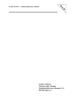
Supplementary
Instructions
Pages
-
Entry
Sub
Operating
1. Connections
The subwoofer is provided with both line level inputs via a pair of phono
connectors and hi-level (speaker level) inputs on a pair of binding posts. Only
one type of input should be used at any one time. The rear panel also features
the mains power input, voltage selector, fuse, remote trigger input and standby
indicator LED. The rear panel input connections are shown in Fig. 1 below:
Fig. 1. Rear Panel
Audio Input Options
Line Level Inputs: These should be used to connect your subwoofer to preamp outputs or integrated
amplifier preamp outputs. For stereo use, use both connections. In a 5.1 system, only connect to one
input. Either left or right is fine and will give the same results.
Hi-Level Inputs: These should be used to connect your subwoofer directly to a stereo pair of speakers,
either via the amplifier outputs or the loudspeaker input terminals themselves. Take care to maintain
correct polarity throughout.
Control Input
The subwoofer is also provided with a trigger input on 3.5mm mini-jack so the subwoofer can be
remotely powered up. The ‘tip’ pin of the mini jack should be connected to trigger signal and the ‘ring’
to ground.
2. Functions/Settings
All functions/settings on the C1 Sub are controlled via a rotary encoder on the front display panel of
the unit and shown in Fig.2 or by the supplied IR remote control. Pushing the encoder knob cycles
through the settings and turning the knob clockwise/anticlockwise increases/decreases the function
value respectively. From the IR remote, Left/Right cycles through the settings and Up/Down
increases/decreases the function value respectively. Below is an explanation of the functions/settings.
Fig. 2 Front Display and Encoder Panel
Level – Shown by ‘L’ on the front display:
Sets the overall input sensitivity of the subwoofer. Initially the level should be set towards the centre
of its range (50) and only adjusted once the upper filter cut-off frequency has been set.
Filter Frequency – Shown by ‘Fr’ on the front display panel:
Varies the upper low-pass crossover frequency. The filter
frequency is the fundamental parameter that defines how the
subwoofer integrates with the
satellite/main loudspeakers. The filter frequency should be set at,
or just above the cut-off frequency of the satellite/main
loudspeakers. To the right is a table of recommended initial filter
settings for the C1 Sub when used with ATC satellite/main
loudspeakers.
Stereo
Loudspeaker
Model
SCM7
SCM11
SCM19
SCM40
Recommended
Initial Sub Filter
Setting
60
56
54
48
Phase – Shown by ‘Ph’ on the front display panel:
Changes the phase of the acoustic output signal with reference to the input signal. This can be used
to improve the integration of the sub – satellite/main loudspeakers by correcting for phase problems
due to different distances from listener to sub and satellite/main loudspeakers. This can be set by
listening to well known material and choosing the preferred setting or, by using a test tone. If using
the test tone method, select a tone at, or very close to the sub-satellite crossover frequency and play it
back through the sub and satellite loudspeakers. Flip the phase setting and listen to which gives the
highest total output. Alternatively, a sound level meter could be used to measure the level.
Display Brightness – Shown by ‘Br’ on the front panel display
Varies the brightness of the front panel display, a higher number leading to a brighter display.
Display On/Off – Shown by ‘Sc’ on the front panel display
The following options are available from this menu:
0
The display stays lit all the time
1
The display stays lit all the time, at the users selected brightness level, and then automatically
changes to minimum brightness after 30 seconds.
2
The display stays lit, at the users selected brightness setting for 30 seconds then turns off.
Note: Quality and level of low frequency sounds can vary enormously in different areas of a typical
room. It is preferable to listen/measure at in more than one location in order to achieve the optimum
setup unless the listening area is very small.
3. Specifications:
Drive Unit:
Frequency Response(-6dB):
Max SPL:
Amplifier Power Output:
Line Level Inputs:
Hi-Level (Speaker) Inputs:
Trigger Input:
Mains Voltage:
Mains Fuse:
Dimensions (HxWxD):
Weight:
12”/314mm
20Hz – 250Hz
103dB
200W
2 x(Stereo) Via Phono Connectors
2x(Stereo) Pairs Via Binding Posts
1x 12v
230v/115v 50/60Hz
3.15A (230V) 6.3A (115V)
450x358x358mm
20kg