1
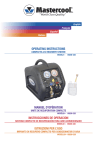
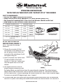
OPERATING INSTRUCTIONS
70070/70070-M/70080 MULTI-SIZE “RATCHET STYLE” TUBE BENDER
SAFETY REQUIREMENTS
• Use only soft copper tubing with this bender.
• Always use personal safety equipment (i.e. safety glasses, gloves, etc.)
• Only personnel knowledgeable in the use of tube benders should use this tool.
• Keep bender dry and lubricate ratchet mechanism.
FORMING RADIUS BLOCK
BENDING RADIUS
3/8” O.D.
(10mm)
1 3/16”
(30mm)
1/2”O.D.
(12mm)
1 3/8”
(35mm)
5/8” O.D.
(16mm)
1 5/8”
(41mm)
3/4” O.D.
(18mm)
2 13/16”
(72mm)
7/8” O.D.
(22mm)
3 3/8”
(86mm)
1 1/8” O.D. (available only in
70080 kit)
����
����
����
���
�
��
����
��
�������������������
�����������������
������������������
����������������
4 9/16”
SETUP AND OPERATION
INSTRUCTIONS (FIGURE 1)
�
����������
�
�������������
NOTE: Tube sizes are outside
diameters!
1) Choose the cross bar (6) that
corresponds to the tubing size that
you are going to bend. Install the
cross bar in the mainframe (4) slot
and tighten wing nut.
2) Select the proper size radius block
(2) and assemble to the tooth
ratchet (3). Press the radius block
onto the square end of the tooth
ratchet.
�
��������������
�
��������������
�
������������
�
���������
�
��������������
3) Set support blocks so that the
FIGURE 1
proper diameter dimensions face
the tubing. Make sure both blocks have the same diameter showing. Place tube between
support blocks and radius block. Start to squeeze ratchet handle (5). The tube will advance
into the radius block. Continue operating the ratchet handle until tube is bent to desired angle.
To ensure an accurate 90 degree angle, use a “square”.
4) To remove tube, pull back radius block by pushing ratchet handle away from the mainframe
and HOLD in place. Push tubing and radius block towards the ratchet handle. Pull tube out of
www.mastercool.com
1
radius block and check the angle of the tube bend using a “square” or protractor.
5) Radius block is removed from the ratchet bar by “wiggling” and pulling block away from the
toothed ratchet.
MAKING 90˚ OFFSET BENDS (FIGURE 2)
1) Mark the required length from the end
of the tubing.
2) Place the tube in the radius block (2)
with the measured mark aligned with a
raised guide line on the face of the
radius block. If the measured end of
the tube is on the right side of the
bender, use the raised left side guide
line. If the measured end of the tube
is on the left side of the bender, use the
raised right side guide line.
������������
�����������
���������������
�����������������
�������������������
������
�����
�����
����
�����������
��������������
�
��
��
��
�
��
�
FIGURE 2
����������
SETUP INSTRUCTIONS FOR REVERSE DIRECTION
BENDING ADAPTER (70070-RD)
����������
BENDS: 1/4”, 5/16”, 3/8”, 1/2”, 5/8”, 3/4”, 7/8” O.D. TUBING
FIGURE 3
(3.1)
(FIGURE 3)
1) Attach adapter (3-1) to bar on bender.
Tighten wing nut.
����������
2) Install adapter (3-2) on bender body
and tighten wing nut.
3) Install desired crossbar and radius block (3-3)
in the usual way.
(3.2)
����������
����������
����������
��������
��������
2
www.mastercool.com
(3.3)
��
��
70070-INS-UNIV