1
BR31293
For the information of Railway Staff only
British Rail
EASTERN REGION
(NORTHERN AREA)
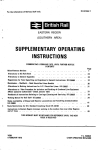
SUPPLEMENTARY OPERATING
INSTRUCTIONS
COMMENCING 8 FEBRUARY 1975, UNTIL FURTHER NOTICE
CONTENTS
Miscellaneous Notices • •
Page
1
Alterations to General Appendix
Alterations to Rule Book • •
18,
20
Regulations for Train Signalling and Signalmens General Instructions (BR.29960)
Instructions relating to the working of 56 ton wagons between Tyne Dock and Consett
21
24
Handbook of Instructions relating to Carriage Cleaning and Servicing BR.29620 • •
Manchester — Sheffield —VVath Electrified Lines Booklet
25
25
Working Manual for Rail Staff BR.30054
25
•
•
Route Availability of Diesel and Electric Locomotives and Travelling Cranes
Booklet B11.29993
30
Route Restriction for BR Standard Coaching Stock BR.29197
Working Instructions for AC Electrified Lines (BR.29987) •
38
40
;
Alterations to "New Procedure for Isolation and Earthing of Overhead Line Equipment
(Where specially Authorised)" Dated January 1973
•• • •
•
•
4 2
THIS BOOKLET MUST BE RETAINED FOR REFERENCE UNTIL THE NEXT
, ISSUE IS RECEIVED.
YORK
8FEBRUARY 1975
F
C
H
.
I
J
E
F
.
SURGE
OPERATING MANAGER
THIS SUPPL EM ENT ARY OPERAT ING I NST RUCT I O NS
BOOKLET S U P E R S E D E S T H E S U P P L E M E N T A R Y
OPERATING I N S T R U C T I O N S B O O K L E T D A T E D
27 JULY 1974. F O R ALTERATIONS T O T HE SECTIONAL
APPENDIX, S E E S U P P L E M E N T N O . 1
8 FEBRUARY 1975.
D A T ED
1
MISCELLANEOUS NOTICES
SPECIAL NOTICE TO ALL SIGNALMEN AND TRAINMEN
When it becomes necessary for a fixed signal to be passed at danger the clear and explicit message
normally given by the signal is lost and the safeguards built in to the lowering of the signal are reduced.
It is important that every Signalman and Trainman should:—
1. O b se rve the code of instructions set out in the General Appendix when using the telephone between
a signal and the signal box so that the Signalman and Trainman reach a clear understanding as to
the identity of the train and exactly where it is standing.
2. Understand the circumstances and conditions in which authority is given for a fixed signal to be
passed at danger.
Nothing should be assumed and nothing should be taken for granted.
INSTRUCTIONS TO TRAINMEN HANDING OVER OF TRAINS TO RELIEF
When a Driver or Guard is relieved he must advise his relief of all matters applicable to the safe and
proper working of the train concerned.
GUARDS OF FULLY FITTED FREIGHT, PARCELS AND EMPTY COACHING STOCK TRAINS
RIDING ON LOCOMOTIVES
The Rule Book, Section H, Clause 4.4
If a brake van in a fully fitted freight, parcels or empty coaching stock train cannot for any reason be
heated, the Guard is authorised to ride in the trailing cab of the locomotive, provided the last two
vehicles on the train are fitted with the automatic brake in working order, and satisfactory arrangements
have been made for the security of mails and scheduled traffic duties.
TWINBOLSTERWAGONS
Tests have shown that there is some possibility of twin Bolster Wagons becoming derailed when trains
in which they are conveyed are propelled.
Propelling movements of such trains along running lines must be kept to a minimum and all concerned
must ensure that the propelling movement is carried out with extreme care.
Where a train conveying twin Bolsters is propelled into an occupied siding it must not be used to push
down the wagons already in the sidings.
In addition, the following special conditions must be stringently observed:
(1) T w i n Bolster Wagons must not be used as runner wagons for over-hanging loads:
(2) E mp t y twin Bolster Wagons must not be marshalled between bogie steel carrying wagons.
MAXIMUMSPEED OF COACHING STOCK
Locomotive Hauled Coaching Stock
Certain locomotive-hauled coaching vehicles have been marked "100m.p.h." or "100 m.p.h. SM" and
guards working trains timed in excess of 90 miles an hour, which will be indicated in the W.T.T. by a
'Plus' sign (+), must if the train is not entirely formed of vehicles marked 100 m.p.h. or 100 m.p.h. SM,
instruct the driver not to exceed 90 m.p.h.
Trains not indicated by a 'Plus' sign (+) in the Timetable must not exceed 90 m.p.h. unless they are
wholly composed of vehicles marked "100 m.p.h." or "100 m.p.h. SM", in which case the driver must be
so advised by the guard.
2
MISCELLANEOUS NOTICES—continued
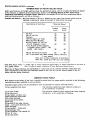
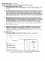
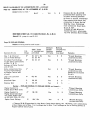
MAXIMUMSPEED OF FREIGHT ROLLING STOCK
Until such times as all freight vehicles bear the appropriate panel, which includes the Maximum Speed
of the Vehicle, in addition to the instructions shown in the Working Manual for Rail Staff, Part 6
Preparation and Working of Freight Trains, Section C, the speeds of the vehicles enumerated below,
when not bearing panels, will be as follows:—
Carflats and Cartics Ma ximu m Speed is 75 m.p.h. subject to any lower restrictions which may be
imposed in particular cases on account of load being conveyed.
Description of Vehicles
Fly Ash
56 Ton Iron Ore
Prestw in
100 Ton Bogie rail Tanks
Merry-go-round Wagons
British Oxygen Co. 100 Ton
G.L.W. Cryogenic Tanks
A.P.C.M. Bulk Cement Wagons
in number ranges LA001 — 190,
LA200 — 294, LA0011
Maximum Speed
Loaded
m.p.h. ,
Empty
m.p.h.
55
25
55
60
45
55
25
55
60
55
60
60 t
35
50
45 Ton Two Axle Oil Tanks
60
60
45 I 2 axle Steel AB) When loaded heavy"
6 0) max. speed.
COV
m . p . h .AB ) In other conditions of load may
open AB) travel up to 75 m.p.h. max speed
1
tlOOT BRTE Bogie Tanks — Loaded light or empty—Maximum Speed 45m.p.h. When propelled or assisted in
Nos 2 0 0 0 0
-When any of these vehicles are marshalled in a train and are of a lesser maximum speed than any
other
in that train the maximum speed of the train will be the lowest speed of any of
2 0 0 marshalled
07
these
vehicles
being
conveyed.
r e a
r
i
n
AMENDED WAGON PANELS
l
i
With
to the safety of the line it should be noted that the wagon panels attached to the following
g regard
h
vehicles
have
been amended as set out below.
t
Amended
o
wagon panels will be provided as soon as possible to replace existing panels.
r12 ton Insulated Fish Vans
The maximum speed has been reduced to 60m.p.h.
in all conditions of loading.
e
m
The maximum speed of these wagons has been reduced
12 ton pipe fitted.
p ton strip
t
to 50m.p.h. in all conditions of loading.
24
coil.
22
ton
timber,
conflat,
coil,
y
plate
fitted only and fitted
cwith roller
o
bearings.
n
22 tondand 24 ton plate—
i
t only.
fitted
20
ton
i
o and 22 ton tube vacuum
fitted
— with plain bearings and
n
roller bearings.
o
22 ton conflat fi t t e d with
fplain bearings only.
12
l tono container, flat conflat 'B'
24
a ton d'D' coil.
22 ton Ale pallet.
—
M
a
x
i
3
MISCELLANEOUS NOTICES—continued.
AMENDED WAGON PANELS—continued.
12 ton PaIvens Nos.B782274
—8782523.
The maximum speed has been reduced to 45m.p.h.
in all conditions of loading.
25V2 ton Sand/Ironstone Hoppers
with a wheelbase of less than loft.
The maximum speed has been reduced to 35m.p.h.
in all conditions of loading.
27 ton Iron Ore Tipplers
Nos.LW25000 LW25099
The brake force of these wagons in the Heavy
and Medium conditions of loading has been
reduced from 21 tons to 15 tons.
Salmon Wagons
The maximum speed has been reduced to 45m0p.h.
in the Heavy Medium and Light conditions of loading.
100 ton GLW Hopper (LS17601 —
17612)
The maximum speed has been reduced to 45 m.p.h. in
the Heavy Medium and Light conditions of loading.
MS12/85/2
CONVEYANCE OF LOADED HEAVY AXLE WEIGHT VEHICLES
(1) L o a d e d 100 ton bogie vehicles must be moved in block train loads and form BR029973/3 must be
issued. When movement of loaded 100 ton tanks or loaded 100 ton bulk cement vehicles takes
place they may be marshalled in accordance with paragraph (8) of these instructions.
(2) L o a d e d bogie tanks and bogie hopper vehicles of a gross laden weight between 80 and 90 tons —
these vehicles must only be moved in block train loads. Where the R.A. Category of the route is
lower than that of the vehicle, form BR029973/3 must be issued. Bogie tanks may be marshalled in
accordance with paragraph (8) of these instructions.
(3) L o a d e d 80/82 ton bogie Pa'vans must be confined to block train load movements except where
specifically authorised to be conveyed on nominated wagon load services. Where the R.A. Category
of the route is lower than that of the vehicle, form BR.29973/3 must be issued.
(4) L o a d e d 81/82/84 ton Strip Coil, Coil K and Coil I wagons may be conveyed in block train loads
or
byBR.29973/3
wagon loadmust
services.
Where the R.A. Category of the route is lower than that of the vehicle,
form
be issued.
(5) L o a d e d 50 ton 2-axle vehicles must be confined to block train load movement except where
specifically authorised to be conveyed on nominated wagon load services. Form BR29973/3 must
be issued. When movement of 50 ton loaded tanks or 50 ton bulk cement vehicles takes place, they
may be marshalled in accordance with paragraph (8) of these instructions.
(6) L o a d e d 45 ton Steel AB wagons must be confined to block load movement except where
specifically authorised to be conveyed on nominated wagon load services. Where the R.A. Category
of the route is lower than that of the vehicle form BR.29973/3 must be issued.
(7) Loaded 40/45 ton 2-axle vehicles, (excluding loaded 45 ton Steel AB vehicles), may be conveyed
in block train loads or by wagon load services subject to instructions in part 6 (White pages) of
Working
Manualform
for Rail
Staff (BR.30054/6).
Where the RA Category of the route is lower than that
of the vehicle,
BR.29973/3
must be issued.
(8) L o a d e d 1 0 0
throughout.
(Pink pages) of Working Manual for Rail Staff (BR.30054/3), provided that the air brake is operative
/
9 0 /8 5 /8 0 /5
0 / 4 Loaded
5 / 4 0100 ton bulk cement vehicles may be inter-mixed with 45/50 ton bulk cement vehicles
provided that the air brake is operative throughout..
M S 1 2 / 8 6 / 0
t
o
n
t
a
n
CONTINENTAL FERRY WAGONS
k
s
Until further notice, the speed of all Continental Ferry Wagons must be restricted as shown below:—
m
a
Continental Ferry Wagons marked
y
SS.1— 75m.p.h. ,(coaching trains)
b
SS. 7
S. ; — 45m.p.h.
e
-unmarked
i
n 6t 0 e — 45 m.p.h.
Special
applies to certain •
r
- dispensation
m .
Quay
—
Edinburgh
—
Glasgow,
S
'
t
y
p
e
v
e
h i c 6E87,
l e s14 16 Glasgow — Edinburgh — Parkeston Quay, 6E88, 21 00 Llandeilr
m
i p x.
e
—Wh itemoor and 6V85, 21 24 March — Severn Tunnel „In. Air Braked services timed to a maximum
w
h h .e
n
d
speed
of 60m.p.h.
Details
areepublished
in the Sectional Appendices, page 257 North and page 330
c
o
n
v
e
yfour
d
s
u
(
South and apply to these
services
only.
o
n
4
MISCELLANEOUS NOTICES — continued
PRIVATELY—OWNEDBULK GRAIN VANS
Brake Sticks must not be used with the above type of vehicle as the design is such that it is not
possible to obtain a safe and secure hold for a brake stick.
MAINTENANCE OF M.G.R. WAGON SETS AT THE MAXIMUM NUMBER AUTHORISED
The authorised load for M.G.R. services to the Base Load power stations is 30 wagons per train and in
order to keep working costs to a minimum all efforts must be made to maintain wagon sets at the maximum
figure. In view of this the following additions apply to the Appendix Instructions at:Cottam
Drax
Eggborough
Ferrybridge
High Marnham
Thorpe Marsh
West Burton
If a defective wagon(s) is detached at the power station the guard must attach the relevant number of
good wagons to bring his train to the maximum load authorised. If however, "green labelled" wagons are
to be detached at ,
that
D o point.
ncaster,
Ka n
o t train
t i on departure from the colliery conveys less than the maximum number of wagons the
If
loaded
deficiency
n g l must be rectified after discharge at the power stations by attachment of the relevant number of
wagons,
e
yor when this is not possible, in accordance with the instructions issued by the Examiner at the
power station.
o
r
Exceptions
W
o
r
Trains on return from Ratcliffe power station must be made up at Shirebrook sidings en route to
kShirebrook
s
oarea collieries, or at Seymour Junction for Barrow Hill area collieries. Trains from Didcot
p
must
be made up at Toton North.
tTrains on return from Fidlers Ferry power station must be made up at Barnsley Junction for Barnsley area
hcollieries or at Wath Yard for South Yorkshire area collieries.
eTrains from High Marnham to be made up at the power station.
a
t
t
In the case of any under-loaded train from a colliery to Thorpe Marsh, the route of which does not pass
a
c
h
through Doncaster,
these must be made up at the power station.
i
n
g
o
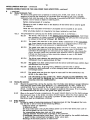
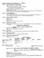
LOCOMOTIVE HEADLIGHTS
f
Certain locomotives and multiple units are being fitted with an electric headlight to improve the sighting
"of approaching trains by staff working on running lines and also to provide forward lighting for drivers.
m
The headlights will in no way modify the requirements of the Rule Book, Section H, Clause 7. They will
abe operated experimentally and then on service trains from dusk to dawn only in the following areas:—
kClass 124 Diesel Multiple Units Based at Hull and eTrans-Pennine
Eastern
w o r k i n g route
o between
n
t h and
e London Midland Regions.
u
1M58
— M a n c h e s t e r
f o l 09
l 48
o w Hull
i n g
1E74
14
57
Manchester
—
Y
o
r
k
p
s
e
l e
cYork t
e
d
1D89
_
H
u
l
l
17
07
"s
r
v Hulli
c
e
s
1M80 e 19 44
_
L
i
v
e
r
p
o o l
w
1E06
o
09 10 n Liverpool
— H
u
l
l
a
1M69
Hull e
_ M a n c h e s t e r
13 48h
t
1P67
17 15
Manchester
g
— B l a c k p o o l
1..120
— M a n c h e s t e r
07
07
Blackpool
o
1E98
Manchester
— Y
o
r
k
12 57
n1M75
15 17
York
— L i v e r p o o l
s1E59
Hull
18 10
Liverpool
m
To assist in assessing the effectiveness of fitting the headlights, it is essential that reports of
uperformance are received from the undermentioned groups of staff:—
s (i) S t a f f working on running lines (C.C.E., C.S. & I.E. etc.) as regards the warning of approaching
t
trains given by the headlight.
b
e
d
5
MISCELLANEOUS NOTICES—continued.
LOCOMOTIVE HEADLIGHTS—continued.
(ii) Driv e rs working the locomotives/multiple units fitted with the headlight to report on "back
glare", if any, experienced in the cab and general effect on sighting of signals and lineside signs
particularly temporary speed restrictions, whilst the headlights are in operation.
(iii) D ri v e rs of oncoming trains in respect of 'dazzle' experienced when meeting a locomotive/multiple
unit with its headlight in operation, with particular reference to signal sighting.
(iv) U n t i l further notice, Drivers are instructed that unless weather c o
the headlights should be left switched on when the locomotives/multiple units are in motion,
.
during both daylight and darkness.
n d itio n s
d o
n o t
a l l o w
Questionnaires
are
directly
available
for
Drivers
staff to specially report experience of the
t
h
e
i
r
u
s
e and C.C.E.
,
headlight and they are asked to complete the appropriate form and hand it on completion of duty to
their Local Supervisor. Other staff are also requested to give comments on the effectiveness of the
headlights when working on or about the track.
These experiments are being conducted in pursuance of improved safety on the line. Your co-operation ir
commenting and criticising is essential. Staff reporting is the best way to judge effectiveness of the
headlight.
.It must be emphasized that staff should not rely on any particular train, in the areas mentioned
previously, being hauled by a locomotive or power car with a headlight in operation.
VEHICLES FITTED WITH A.F.I. VACUUM BRAKE EQUIPMENT IN TRAINS WORKED
BYSOUTHERN REGION LOCOMOTIVES OR DESTINED FOR THE SOUTHERN REGION
Vehicles fitted with A.F.I. (Accelerator Freight DA Inshot) vacuum brake equipment must not be
included in the fitted portion of a partly fitted vacuum brake train if the train is to be worked by a
locomotive allocated to the Southern Region, or if the destination of the train is located within the
Southern Region.
Vehicles fitted with A.F.I. equipment can be identified by either a metal plate with the letters "A.F.I.
or these letters painted on the solebar on each side of the vehicle.
Southern Region locomotives are numbered in the series:—
Electric C l a s s 71
71001-71014
Diesel Electric C l a s s 33
33001-33212
El ectro-D iesel C l a s s 73
73001-73142
Electro-Di esel C l a s s 74
74001-74010
WAGONS FITTED WITH DISC BRAKES
All wagons fitted with disc brakes, with the exception of those listed below, are permitted to be used in
the fitted portion of not fully-fitted trains.
Wagons not permitted :—
Hop AB (MGR)
17— ton Fly-Ash
21 — ton Fly-Ash
24— ton Hopper Coal
M
S
1
2
/
8
5
/
3
1
CONVEYANCE OF BOGIE PALLET VANS FOR SHELL STAR LIMITED
Before this type of vehicle is accepted for conveyance either loaded or empty, the Area Manager responsible for the Depot, or his nominated representative at the originating point, must ensure a certificate is
obtained from Shellstar Ltd. stating that the bogie pallet van/vans is/ are correctly loaded and secured
safe for despatch, and the Guard of the train must be advised that the certificate has been received for
such vehicles on his train.
The certificate must be retained by the Area Manager concerned for six months.
MANNING OF LOCOMOTIVES REQUIRED TO EXAMINE A SECTION OF LINE IN AN EMERGENCY
In the event of it being necessary for a single-manned locomotive to be utilised to examine the line
in an emergency under the provisions of Block Regulation 15 and another man in the Footplate line of
promotion is not readily available, i t is permissible for another responsible member of the staff compe-
tent in the Rules and Regulations, such as a Guard or Station Manager, to act as Secondman for the
purpose of the examination.
MISCELLANEOUS NOTICES—continued
6
CLASS 40: DIESEL LOCOMOTIVES
These locomotives must each carry two wooden scotches and when the locomotives are left stabled
Drivers must in addition to applying the handbrake place a wooden scotch on each side of one wheel.
Before the locomotive is moved the scotches must be removed and placed in the locomotive cab.
SECURITY OF DETONATORS
A member of the staff lost his satchel containing, amongst other things, 12 detonators and the Home
Office have expressed concern at the nature of this loss and the dangers which result.
Staff whose duties require them to carry detonators are reminded of their responsibilities for safe
custody of the detonators in their possession. In the event of loss the facts must be reported immediately.
REGULATIONS FOR TRAIN SIGNALLING AND SIGNALMEN'S GENERAL INSTRUCTIONS
The phrase '(Where specially authorised)' which follows the description of a Class 9 Unfitted freight
train in the "Bell Signals" applies only to the classification of the train as laid down in the General
Appendix.
The Is Line Clear/Train Description bell signal 1-4 may be used without special authority.
LINES WORKED ON THE TRACK CIRCUIT BLOCKSYSTEM
1. A b so lu t e possession of running lines for Engineering purposes necessitating a complete stoppage
of traffic on such lines.
Referring to the instruction in the Rule Book, Section T, Part mr
operation,
no movement must be made outside the detonators in either direction without the
permission
of the Signalman concerned. Before authorising a movement to the rear the Signalman
T apply the
must
instructions contained in the General Appendix, headed "Wrong direction movements
where
Track Circuit Block is in operation".
N inhs e
r e
Tout-of-gauge
r a c k and exceptional
C i r c loads.
u i t
2. T ra
conveying
B
l
o
c
k
i
s
Arrangements for any wrong direction movement which is required must be made in accordance with
i instruction
n contained in the General Appendix, headed "Wrong direction movements where
the
Track Circuit Block is in operation".
45-TON GROSS LADEN WEIGHT TWO-AXLE AIR-BRAKED VANS (COV AB)
Brake sticks must not be used to apply brakes on these vehicles. The brake lever is long and the lever
ratio is, therefore, high to enable adequate braking without the use of a stick. 1 ) A S . 1 2 / 8 6 / 6 / 1
FREIGHTLINER CONTAINER DEFECTS AND LOOSE SHEETS ON OPEN CONTAINERS
In all cases where Freightliner trains are delayed on route through container defects on loose sheets on
open containers, the container number or numbers must be given by the Guard to the Signalman for
transmission to the Divisional/District Control concerned. M 0 1 1 / 0 3 6 / E
FREIGHTLINER AND MOTORCAR TRAINS
Increasing number of Freightliner trains are now operating in all Regions. One respect in which these
Freightliner trains differ from ordinary trains concerns the direction of travel of the container.
All Freightliner Terminals are laid out to deal with Containers facing in one direction only. This is to
make possible a one way only circulation of road vehicles which is desirable for safety and necessary
for speed of operation.
All Freightliner trains are carefully scheduled to ensure that they arrive at the Terminal with the
Container doors, which are at one end only of the container, at the appropriate end. Containers are
moreover, identified by their position from the leading end of the train.
As confusion and delay could arise from a Freightliner train arriving in the Terminal the wrong way round,
steps should be taken, where necessary, to provide for the reversal of the complete train en route.
Unschedul
round.
When diversions have to be made, the effect on the direction of travel must be considered and
,
arrangements
made, wherever possible, for the train to arrive at the destination Terminal facing the
ed
correct
way.
"Similar
considerations apply to motorcar trains when the cars are normally driven the
d i v of
e rthe train to an
length
end dock unloading point and arrival with all the vehicles loaded wrongly round
s i entail
o n s considerable difficulty".
can
f r
MISCELLANEOUS NOTICES — continued
7
REGULATIONS FOR WORKING THE AUTOMATIC AIR-BRAKE ON LOCOMOTIVE OPERATED TRAINS
CONVEYING VEHICLES EQUIPPED WITH DISTRIBUTORS AND OPERATING ON
THE TWO-PIPE SYSTEM
Drivers should note that the above Regulations are amended insofar as the 'release' position (where
provided) of the Drivers automatic air-brake valve should only be used in the following circumstances:1. Immediately following the completion of the 'continuity' or 'complete' brake tests.
2. I f dragging brakes are suspected when running.
3. I f it is essential to release the brakes more rapidly than is possible using the RUNNING position
especially following a series of brake applications. (This should normally only be necessary when
working trains of considerable length).
4. I n releasing the brakes if the previous application had been made _ʻhen an overcharge pressure
existed in the brake pipe.
Drivers should also note the following points:—
(a) I f a brake application is initiated when an overcharge pressure exists in the brake pipe and
the 'release' position is not correctly used afterwards, brake drag and consequent damage
can result on the train vehicles.
(b) Wh e n the brake valve handle is placed in the 'release' position it must be held for not less
than 1 minute to allow for complete release of all brakes in the train.
AIR BRAKED L O C O M O T I V E
The attention
of Drivers, Guards and other Operating staff concerned with air braked trains is drawn
H Athat
ULE
D air braked vehicles have had the main reservoir pipe isolating cock temporarily
to the fact
some
placed into
position and the handle removed.
V Ethe
H closed
I C L (isolated)
E S
- on these vehicles then operates as a single pipe system, although the continuity of the main
The brake
reservoir
the train is not in any way affected.
Mpipe
A Ithroughout
N
R on
E one
S of these
E Rvehicles
V
If the brake
requires to be isolated in service, only the distributor isolating
cock requires
to R
be placed in the "brake isolated" position and the release cord pulled in the normal
O
I
way.
P
I
P
E
TRACK CIRCUIT OPERATING CLIPS
I
S
O
L
A
Track circuit
T
operating
I
N clips,
G as described on page 3 of the General Appendix, are being progressively
distributed
mentioned and installed in driving cabs, brake vans and Guards compartments.
C to the locations
O
The equipping
of
every
locomotive
and vehicle will necessarily take some time, during the interim
C
K
period, train equipment should not be considered as incomplete if the track circuit operating clip (s) ib
S
not available.
As the equipment becomes available, it must be used in accordance with the instructions laid down in
the Rule Book, Section M and Section T, Part
LOCOMOTIVES AND MULTIPLE UNITS - ROUTE INDICATOR BLINDS
Certain Deltic locomotives have been experimentally fitted with a modified four figure route indicator at
both ends.
The modification consists of an opaque black sheet attached to the existing front glass of the route
indicator. There are two translucent white discs, back illuminated by the existing lamps serving the two
outer digits.
The provisions of the Rule Book, Section H, para. 7.1.1. will require the route indicator box to be
illuminated at all times.
PREPARATION OF FREIGHT TRAINS
A man rostered to fully prepare a freight train must
1. C h e c k that the vehicles are correctly marshalled, labelled, coupled and safe to travel, with all
doors
Clauseclosed,
6.3. sheets and chains etc. secured in accordance with the Rule Book, Section H,
2. E n su re that a tail lamp, and side lights when required, are provided in accordance with the Rule
Book, Section H. Clause 7.4.
MISCELLANEOUS NOTICES—continued
8
PREPARATION OF FREIGHT TRAINS — continued
3. E n su re that the train load is suitable for the class of train concerned, within the capacity of the
locomotive and the required brake force is available, in accordance with Section 6 of the Working
Manual for Rail Staff.
4. Co mp le te Train Preparation Forms (B.R.20896/- and B.R•20896/138) and a Train Preparer's Load Slip
(B.R.29976) and hand them to the Train Guard or, in the latter's absence to the person in charge.
A guard who is handed Form B.R.29976 fully completed and signed, is not required to carry out
preparation duties for the train concerned.
M
.
S
.
1
2
/
8
5
/
7
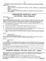
SUPPLY OF ELECTRICPOWER TO COACHING STOCK TRAINS
In amplification of Sectional Appendix Instructions (Northern Page 252: Southern Page 302), the following
should be noted by guards of trains composed wholly or partially of M U D stock, including those sets
which include w i n vehicles in the formation:
1. Journeys from carriage sidings or stabling point to station or terminus prior to going into service.
When a locomotive which is not capable of providing electrical supply is working the E.C.S., the
air-conditioning Master Control Switch in each MICIID vehicle must be switched "OFF"
("AUXILIARIES ONLY" position in the case of MK.III vehicles) and must remain in that position
until an electrical supply is provided e . g . shore supplies or train engine for forward working as a
passenger train, guard or other staff concerned then to switch "ON" the air-conditioning Master
Control Switch in each vehicle ("AUXILIARIES AND AIR CONDITIONING" position in the case of
MK.III vehicles).
Failure to carry out the foregoing will adversely affect the pre-conditioning of the vehicles which
has been previously carried out.
2. Fa ilure of E.T.H. locomotive on Passenger trains en route.
(a) During cold weather. When such a failure occurs and cannot be rectified, or a fresh locomotive
capable of providing an electrical supply is not available, the air-conditioning Master Control
Switch in each MICIID vehicle must be switched to the " O W' position ("AUXILIARIES ONLY"
position in the case of MK.III vehicles) in order to avoid the circulation of cold ambient air
into the coaches to the discomfort of passengers.
Under these circumstances, the coach lighting should be used as economically as possible
during daylight to conserve batteries.
(b) During warm weather. Under the locomotive circumstances described above, the air-conditioning
Master Control Switch in each MK.IID vehicle may be left in the "ON" position ("AUXILIARIES
AND AIR CONDITIONING" position in the case of MK.III vehicles), to enable circulation of
cool air but this arrangement must not be applied for a longer period than 2 hours.
ABOLITION OF BRAKEVANS ON FULLY—FITTED FREIGHT AND PARCELS TRAINS
Guards on fully-fitted freight and parcels trains travelling in the rear cab of the locomotive must not,
many circumstances, interfere with or attempt to use, any of the driving controls.
GUARDS REPORTS ON FREIGHT BRAKE VAN DEFECTS
(OTHER THAN HOT AXLE BOXES AND WHEEL/AXLE FAILURES)
Freight Brake Van defects must be reported on Form B.R. 29206 " G u a rd s Reports on defects in Coaching
Stock". The form, when completed, must be handed to the Supervisor on arrival at destination or to the
relieving guard(s), if relieved on route, for handing to the Supervisor at destination.
On receiving the completed Form B.R. 29206, Supervisors must ensure that the C & W Repair Staff are
made aware of the reported defects.
DETACHING OF CRIPPLED 26/32 TON COAL HOPPERWAGONS FROMPERMANENTLY COUPLED
COAL TRAINS
Unlabelled loaded wagons detached crippled from Permanently coupled Coal Trains must be labelled by
the Guard of the train for the purpose of identification and working to destination later. All detached
wagons must have labels showing the wagon number, destination, loading colliery and date despatched,
and details of train detached from.
The Guards must also endorse the Train Weighbills carried on the train, showing against the individual
wagon number where the cripple was detached.
MISCELLANEOUS NOTICES — continued
9
EXPLOSIVES MILITARY — USE OF FIREFIGHTING CLASSIFICATION SYMBOLS
Ministry of Defence have been given authority to attach firefighting classification symbols printed on
yellow-coloured background labels measuring 1' x1' on vehicles conveying H.M. Government explosives.
Labels will be attached by senders and detached by consiqnees.
Rail staff are in no way concerned with these labels. They are intended purely as visual aids to fire
service personnel attending a mishap.
SAFETY OF THE LINE —REPORTING PROCEDURE
In all cases of displaced loads, the following procedure is to be carried out:—
1. A l l incidents on the running line to be reported to Divisional Control.
2. T h e Guard, when making his report, must advise the following information:—
(a) T y p e of train and whether fully fitted or partially fitted.
(b) T y p e of brake in use on the train.
(c) V e h ic le concerned and number.
(d) T y p e of coupling in use and its position.
(e) A n y other factor which in his opinion may have influenced the incident, e.g. heavy braking,
rough riding of vehicle, excessive speed.
These details must also be included in the Guard's Journal. The report must be completed even in
instances where the Guard makes an adjustment without detaching the vehicle and so avoiding the need
for site attendance by a Loading Inspector.
M
T
1
2
/
1
1
.
1
CONDUCTORS ON C.C.E. MECHANISED MAINTENANCE MACHINES
On C.C.E. Mechanised Maintenance Machines not fitted with D.S.D. equipment. Notices are being fitted
relating to "Engine Stop" and "Hand Brake".
In cases of emergency, the Conductor must apply the hand brake and then operate the Engine Stop Button
until the machine comes to rest.
(
M
P
3
7
/
6
/
1
1
)
PIPE TRAFFIC ON BOLSTERWAGONS
The recent ban on loading 6 long pipes in accordance with Working Manual Instruction E.1(ii) is amended
forthwith and it is now permitted to load 5 long and 1 short pipes on Bolster wagons, with the 5 long
pipes secured to the wagon in 2 tiers, and the short pipe placed on top and secured independently to
the wagon.
(
M
T
6
/
2
.
1
(5))
ROBELTRACK LINING/RECORDING MACHINE, TYPE 24.21
This machine must be worked in accordance with the instructions shown in pages 62 to 69 of the
General Appendix for Lining Machines. In addition, the outside consolidators must always be in the
stowed position when travelling to and from the site of work and when recording.
When the machine is used, on Track Circuit Block lines or in a section where intermediate Block signals
exist,
solely for recording, the Engineer is not required to take Absolute Possession of the line
concerned.
The maximum speeds at which the machine may be run are as shown below:Over Switches
and Crossings
Plain line
When running under own power, not recording
When recording
2 5
15
1
1
5
5
MATISA TYPE BNRI 85 — TAMPING/LINING MACHINE
Theabove-named
following Instructions
the
machine:-must be strictly observed in connection with the operation and movement of
1. T h e Instructions applicable to the Tamping/Lining Machine Type S I X . , as shown in the General
Appendix,
must be applied at all times, except that the following maximum permissible speed must
be observed:(a) O n plain line
—
25 m.p.h.
(b) O v e r switches and crossings — 15 m.p.h.
1
0
WORKING INSTRUCTIONS FOR THE HIGH SPEED TRAIN (PROTOTYPE)
(NOTE: These instructions supersede all previous Working Instructions for the prototype train).
1. INTRODUCTION
1.1 The prototype High Speed Train is a diesel electric multiple unit consisting of 2 x 2250 h.p.
power cars and 7 BR. Mark ill coaches, although initially only 6 coaches will be provided.
One power car is attached to each end of the train and the formation must not be varied
unless specially authorised by the Regional C.M. & E L , except that in emergency, one or
more coaches may be detached — see clause 13.2.
MISCELLANEOUS NOTICES — continued
1.2 T h e power car consists of a driving compartment, an electrical equipment compartment, a
diesel engine compartment, a radiator compartment and a luggage compartment. The luggage
compartment is provided with gangway access to the train. Two compartments are provided in
the rear end of the power cars within the luggage compartment and on each side of the centre
gangway. These are the guard's riding compartment and the guard's brake compartment. (The
latter was formerly the auxiliary driving compartment but the driving controls have been
removed).
1.3 T h e guard's riding compartment of the rear power car will be the guard's normal riding position.
Gauges which are applicable to the guard's duties are in the brake compartment and are as
follows:—
A brake pipe pressure gauge.
Duplex brake cylinder pressure gauge.
A Duplex main reservoir pressure gauge.
The Duplex main reservoir pressure gauge indicates the pressure in the main reservoir of the
power car on one scale and the pressure which is fed into the main rerservoir pipe of the train
on the other scale.
Additionally in the luggage compartment there is a luggage loading gauge which indicates the
maximum weight which can be carried.
1.4 Apparatus in the guard's brake compartment which is relevant to the guard's duties is as
follows:—
An emergency brake valve.
A "Train Lights On" switch.
A "Train Lights Off" switch.
A Driver-Guard communication control unit equipped with an isolating switch and a call
buzzer.
Audio Navigator equipment.
Guard-Passenger communication control unit.
2 sets of track circuit operating clips.
1.5 Wh e n power cars only are being transferred from one point to another, they must be run in
pairs, with the gangway ends coupled, in which case they must be signalled and dealt with
as for light locomotives. A single power car may be hauled by a locomotive equipped with
automatic air brake equipment.
1.6 T h e standard instructions for coupling and uncoupling electrically-heated buckeye stock are
applicable to the High Speed Train, but additionally a 3 6
disconnected
and stowed in its dummy socket when the stock is uncoupled and connected
when the stock is coupled.
way c o n t r o l
j u m p e r
m
u
s
t
2. MODIFICATION OF RULES
l
s
o modified:—
2.1 T ha e following
rules are
21.1
Se c tion
b
e H (Clause 3.2)
The driver must check that the detonator cupboard in the main driving compartment
is sealed, as an indication that the contents are complete. If the cupboard is not
sealed, a check must be made to ensure that it contains 12 detonators, 1 red flag and
1set of track circuit operating clips.
MISCELLANEOUS NOTICES — continued
WORKING INSTRUCTIONS FOR THE HIGH SPEED TRAIN (PROTOTYPE)—continued
2. — continued
2.1.2 Section H (Clause 3.22)
The driver is forbidden to leave the driving compartment without ,—
(a) Removing the master key.
(b) Moving the automatic brake controller to EMERGENCY.
(c) Applying the parking brake.
2.1.3 Section H (Clause 5)
Guards
working
the High Speed Train will be required to undertake the following
additional
duties:—
Operation of the lighting and air-conditioning switches.
Operation of Audio Navigator Equipment and Guard/Passenger communication
control unit.
Coupling and uncoupling in an emergency.
Assisting the driver, as shown in clause 13.2.
2.1.4 SectiOn H (Clauses 5.2.1 and 7.2)
The guard is responsible for ensuring that the destination indications are correctly
displayed on each side of the train.
2.1.5 Section H (Clause 7.3.1)
The High Speed Train is fitted with an electric tail light, which must be switched on
by the driver. This must be illuminated during daylight as well as during darkness.
The guard must ensure the tail light is switched on before starting.
2.1.6 Section K (Clause 3.7.3)
Hand brakes are not provided in the guard's brake compartments of the High Speed
Train and the guard must advise the driver that he is leaving the train to protect it in
accordance with this Rule. The guard must inform the driver of his return to the train.
2.1.7 Section M (Clause 3.2)
Should the accident result in a fire breaking out, the driver must take the necessary
action to extinguish it and carry out the provisions of Section M, Clause 7. The
guard must protect the opposite line in accordance with Section M, Clause 3.2.1.
3. DISPLAY OF HEADLIGHTS
Indicator boxes are not provided. Two marker lights are displayed horizontally irrespective of the
classification of train. In addition, a headlight which may be illuminated at all times is placed
centrally between the marker lights. The Regulations on page 85 of the General Appendix do not
apply to this train.
4. DUTIE S OF PLATFORMSUPERVISORS
4.1 T h e maximum weight of parcels, mails, luggage and other articles loaded in the luggage
compartment of power cars must not exceed a total of 1 ton when the power car is fully
fuelled. The person in charge of the station platform at which any of this traffic is loaded must
ensure that this limit is not exceeded. The luggage loading gauge (referred to in Clause 1.3)
will indicate whether the load limit has been reached, and must in all cases be looked at to
check that the maximum permissible load has not been exceeded.
4.2 T h e person in charge of the platform must also assist, if it is necessary, to detach a
defective coach — see Clause 13.2.
5. BEFORE THE JOURNEY
All normal regulations for pre-conditioning Mark III coaches apply to the High Speed Train, see also
Section 7.
6. DURI NG THE JOURNEY
All normal regulations for the operation of Mark III coaches must be observed during the journey.
12
MISCELLANEOUS NOTICES — continued
WORKING INSTRUCTIONS FOR THE HIGH SPEED TRAIN (PROTOTYPE )—continued
7. T RAI N PREPARATION FOR SERVICE BY GUARDS
7.1 B e f o re taking charge of the train, guards must obtain, in addition to normal equipment, a tape
cassette labelled as per the train to be worked. This is for use in the Audio Navigator
equipment.
7.2 T h e guard must check on each coach that the distributor isolating handle which is painted
red is in the vertical (brake operative) position, and the main reservoir isolating cock handle,
which is painted yellow, is in the horizontal (open) position. If the distributor isolating
handle is found in the horizontal (isolated) position but the vehicle is without a "For Repair Automatic Brake Defective" label, the handle must be placed in the vertical (brake operative)
position. The main reservoir pipe isolating cock must also be checked to ensure that it is in
the horizontal (open) position.
7.3 Wh e n an internal or external heating supply is available, the air-conditioning equipment must
be switched on in each train vehicle by inserting a carriage key into the control panel. life
key must be inserted with the stem pointing upwards to the position marked OFF. The key must
then be turned through 1 8 0
0period, the green lamp will illuminate to indicate that the auxiliary and air-conditioning
,equipment
u n t i lis functioning.
t h e If, however, the train is to be run empty, the control switch must be
turned
through
90
sThis twilleenable
m
motor/alternator unit to run and the coach lighting and internal door
0
io
n i n the
pcontrol
t wills operate.
equipment
e
t i t h oe r
7.4 Ina
d ividUu a lXcoach
A
I lighting
L I or full train lighting can be operated by a lighting control panel
cA
l Ro to
kE Auxiliary
adjacent
and Air-Conditioning control unit. Train lighting can also be
Ic the
S
w
switched
i
s
on
e
from
the
guard's
brake compartment of either power car. The train lighting can
a
n
only be switched on Or off if the auxiliaries and air-conditioning switch in the coach concerno
ded is away from the OFF position.
rA
.
a n t .i
8. BRAKECREGULATIONS
-A
f
8.1 The
Regulations
for Working the Automatic Air Brake on Locomotive-operated Trains (as shown
ctin the
l General
o e c Appendix) apply to this train, with the exceptions as shown below:—
kr w i s
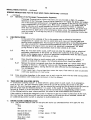
8.1.1 A l l pressure gauges are calibrated in units of BAR, which is the unit of pressure
e
a
specified in the new International System of Units (Systems Internationale or S.I.).
d
i
r
b8.1.2 O
n e r bar is equivalent to approximately 14.5 p.s.i. i.e. slightly less than atmospheric
e
c
pressure.
i
e
tf
i
o
n
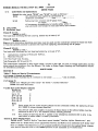
HST Pressure
t
Description
P.S.I.
o
Bar
Equivalent
A
U
X Main reservoir
I
maximum
L
I
pipe
A Main reservoir
R
10
7
145
101.5
I BrakeE pipe, RUNNING
5
72.5
S
O Brake pipe, FULL SERVICE
3.5
50.2
N
L8.1.3 T h e brake equipment on the Mark III coaches is of the standard British F ailways
Y
2-pipe system. Caliper-disc brakes are used on all wheels.
.
MISCELLANEOUS NOTICES — continued
13
WORKING INSTRUCTIONS FOR THE HIGH SPEED TRAIN (PROTOTYPE)—continued
8. — continued
8.2 Bra k e Continuity Test
8.2.1 T h e driver and guard must co-operate in making this VITAL test which is for the
purpose of proving the continuity of the brake pipe throughout the train. A brake
continuity test must be made in the following circumstances WITHOUT EXCEPTION :—
Before a train leaves a depot or stabling point.
Before commencement of a journey.
Whenever a train is taken over in the absence of the former driver and/or guard
(or shunter).
After the train has been re-formed or uncoupled and re-coupled at any point.
After any brake defect or irregularity has been isolated or rectified.
8.2.2 T h e procedure for carrying out the brake continuity test is as follows:—
8.2.2.1 T h e driver, who must be in the leading main driving compartment, must move
the automatic air brake controller to RUNNING and carry Out the instructions
as shown in the Driver's Manual, BR. 33056/36.
8.2.2.2 T h e guard, who must be in the guard's brake compartment of the rear power
car, must check that the brake pipe pressure is approximately 5.0 bar and
iTimain reservoir pipe pressure is approximately 7.0 bar.
8.2.2.3 T h e guard must open the emergency bra keva lye for 1
/z m i n the
u tbrake
e , pipe
o pressure
b s e falls
r vand
e that the pressure rises in the brake
cylinders
of
both
bogies
as
indicated
on the duplex gauge. On closing the
t
h
a
t
valve, he must check that the brake pipe pressure rises to approximately
5.0 bar and that brake cylinder pressure reduces to zero in the brake
cylinders of both bogies.
8.2.2.4 T h e driver must observe the resulting drop in brake pipe pressure and
subsequent rise to approximately 5.0 bar.
8.2.2.5 T h e guard must then communicate with the driver and both must confirm their
satisfaction with the test.
8.2.2.6 T h e driver must, if driving from a different cab from that in which
preparation was preformed, or after changing ends, press and release the
overcharge button.
8.2.2.7 T h e guard must not give the signal to start until he has carried out h is
duties in the above test.
8.2.2.8 T H E DRIVER MUST NOT START THE TRAIN UNLESS HE HAS OBSERVED THE
FALL AND RISE OF PRESSURE ON THE BRAKE PIPE PRESSURE GAUGE IN THE
LEADING DRIVING COMPARTMENT.
8.3 Duri ng the journey
8.3.1 S h o u ld the guard find, during the journey, that the brake pipe pressure gauge indicates
less than the normal brake pipe pressure. (i.e. approximately 5.0 bar), unless he is
satisfied that this is caused by the driver's brake application, he must advise the
driver, in order that the train may be stopped to establish the cause. If he is unable
to communicate with the driver, the guard must apply the brake.
8.3.2 Wh e n in the guard's brake compartment, the guard should observe on the duplex gauge
that pressure rises in the brake cylinders of both bogies, when the driver applies the
brakes. If a rise in pressure in the brake cylinders of both bogies is not indicated,
the driver must be immediately informed.
8.4 Bra k e Defects
8.4.1 Fa i l ur e to create a brake pipe pressure of approximately 5.0 bar throughout the train
may be due to one or more of the following defects:—
Defective power car apparatus.
A defective coach.
The front brake pipe cock on the leading power car or the rear brake pipe cock on
the trailing power car not fully closed.
An intermediate brake pipe cock not fully opened.
Leakage between flexible hose couplings on the vehicles.
A passenger communication valve open. This will be noted by the audible indicator,
A guard's brake compartment emergency brake valve open.
Blockage of the brake pipe by an obstruction.
MISCELLANEOUS NOTICES continued
14
WORKING INSTRUCTIONS FOR THE HIGH SPEED TRAIN (PROTOTYPE)—continued
8. — continued
8.4 —continued
8.4.2 I f before starting, a brake pipe pressure of approximately 5.0 bar cannot be created
throughout the train, the driver must be informed.
8.4.3 I f the leading power car is found to be in order, the guard must inform the person in
charge, who must arrange for the vehicles to be examined and tested.
8.4.4 l i t h e brake will not release on any vehicle, the distributor release handle, indicated
by a white star, must be pulled. If the brake still cannot be released, the main
reservoir isolating cock, painted yellow, must be moved to the vertical (closed)
position and the distributor isolating handle, painted red, must be moved to the
horizontal (brake isolated) position. The distributor release cord must then be pulled
again.
8.4.5 l i t h e brake on any vehicle is found to be dragging, the release cord must be pulled.
If this does not release the brake, it should be isolated as described in the previous
paragraph. If the brake does not release and the defect cannot be remedied, the
vehicle must be detached at the first available point, any movement being made at
reduced speed.
8.4.6 I f the brake on any intermediate coach is isolated, the driver must be informed and
instructed to limit the speed to 10 m.p.h. below the maximum permitted speed limit.
Similarly if the brakes on two coaches are isolated, the driver must be instructed to
limit the speed to 20 m.p.h. below the maximum permitted speed limit. The foregoing
speed reductions do not apply on lines where the maximum permitted speed limit is
40 m.p.h. or less, but the driver must reduce speed as necessary having regard to the
brake power available.
The train must not be permitted to commence a journey with the brakes isolated on
more than two coaches. If the brakes become defective on more than two coaches on
the train during service, it may be worked forward at a reduced speed having regard to
the brake power available to the nearest convenient point where either the defect
can be remedied or the defective vehicles detached.
8.4.7 T h e train must not start if the brakes are isolated on both bogies of either power car.
One bogie isolated on either power car must be regarded as the equivalent to one
intermediate coach and the speed limited accordingly. Should the brakes on both
bogies of either power car become inoperative during the journey, the train must not
proceed until a locomotive or a fully-fitted air or vacuum braked train has been
attached to the defective power car.
8.5 Defective Brake Pipe
8.5.1 I f a brake pipe becomes defective on any vehicle during the journey, the brake pipe
cock next in front of the defective vehicle must be closed, and the pipes uncoupled
and placed on the brackets.
8.5.2 T h e brake pipe cock at the leading end of the defective vehicle must then be fully
opened and the brake released by hand on the defective vehicle and all others in the
rear.
8.5.3 T h e automatic brake will be inoperative on the defective vehicle and those in the
rear. The train must not proceed until either a locomotive or a fully-fitted air or
vacuum braked train is attached to the rear of the train. The train may then proceed at
a reduced speed having regard to the brake power available.
8.6 Defective Main Reservoir Pipe
8.6.1 I f a defect occurs to the main reservoir pipe, either before starting where it is not
possible to remedy the defect without delay, or en route, the main reservoir cocks on
either side of the defective hose must be closed. The train will then continue to
operate under the •2-pipe - system, i.e. with the air being supplied from each end of
the train.
8.6.2 I f a defect occurs to a second main reservoir pipe, the main reservoir cocks on either
side of the defect must be closed. The brake throughout the portion between the
defective pipes will then be working 'single pipe' and the driver must be advised of
the number of vehicles working "single pipe". When there is no main reservoir supply
of air, the automatic internal doors must be manually operated on the affected vehicles
and the guard should inform the passengers accordingly. Increased internal noise and
vibration may also be experienced, due to deflation of the secondary suspension.
15
MISCELLANEOUS NOTICES - obntinued
WORKING INSTRUCTIONS FOR THE HIGH SPEED TRAIN (PROTOTYPE)-continued
8. - continued
8.7 Operation of the Passenger Communication Apparatus
Passenger Communication Valve Indicators are not provided on Mark III coaches.
Operation of the Passenger Communication Apparatus will apply the brake and reduction in the brake pipe pressure will indicated by the gauges in the driving and guard's
brake compartments of the power cars. When there is pressure in the brake pipe, an
audible indicator will sound beneath the vehicle concerned. If there is reason to
think that the apparatus has been used, but not noticed by the driver, the guard must
stop the train by application of the emergency brake valve. The apparatus must be
reset
by means
has been
used. of a carriage key which is inserted beneath the operating handle that
9. F I RE PRECAUTIONS
9.1
I
n
the event of an outbreak of fire in the engine room or electrical equipment
compartment of a power car, the fire alarm bells will ring in all driving cabs and
guard's brake compartments. The engine wi II stop automatically in the affected power
car, after which B.C.F. (bromochlorodifluromethane) vapour will be automatically
discharged in the engine room and electrical equipment compartment. All doors
giving access to these compartments must be kept closed at all times.
9.2
W h e n the fire alarm bells sound, staff must not enter the engine room or electrical
equipment compartment of the power car without the authority of the driver. Any
person in the engine room or electrical equipment compartment when the bells sound
MUST LEAVE IMMEDIATELY and close all doors.
9.3
C a r e should be taken to avoid contact with, or inhaling of, the B.C.F. vapour. If
contact is made with the vapour, the following precautions should be taken:9.3.1 Re mo ve the person concerned away from the discharge area, to a place where there
is plenty of fresh air. Arrange for medical aid if the person appears to have been
affected by the vapour, stating that he has been affected by the discharge of a B.C.F.
fire extinguisher.
9.3.2 I f any liquid from a fire extinguisher enters the eyes, flush them as soon as possible
with large quantities of clean water.
9.4 F i r e s occurring elsewhere in the power cars or train must be dealt with by hand extinguishers
in a cco rd a n ce
,
10. TRAIN wit
HEATING
ISOLATING SWITCH
h
A "train
i nheat
s t isolating
r u c t switch" is fitted behind a glass panel in each coach. In an emergency,
such asi o
fire,
the train heating supply should be cut off by turning the switch to the OFF
n etc.,
s
position. The train heating supply will not be restored by turning the switch back to the ON position
o nmustt be informed whenever it is used. In the event of fire, the provisions of
and thecdriver
n e7 of the Rule Book must be carried out and the air conditioning control switch
SectionaM, iClause
of the affected
d
vehicle must, where possible, be turned to the AUXILIARIES ONLY position.
i
If the vehicle
in which the emergency arose is retained in the train after rectification of the fault,
the train
n heating isolating switch must be turned back to ON and the driver informed, before the
air conditioning
control switch is returned to AUXILIARIES and A.C.
t
h
11. DRIVER/GUARD COMMUNICATION
e e standard buzzer code for multiple-unit trains (as amended below) will apply for this
11.1 Th
train:F
i
r Stop e
1
ring
M Start a
2
rings
n Set back
u
the train
3
rings
a Guard
l of
. attend
telephone
aSlow
l down when
-propelling
4
rings
16
MISCELLANEOUS NOTICES — continued
WORKING INSTRUCTIONS FOR THE HIGH SPEED TRAIN (PROTOTYPE )—continued
11. — continued
11.1 — continued
Driver or guard
5
rings
leaving train in
accordance•with Rules
Draw forward
6
rings
These buzzer codes must be acknowledged by repetition.
11.2 When the train is running, the driver/guard communication control unit must only be used for
emergencies.
12. OPERATION OF THE AUDIO NAVIGATOR EQUIPMENT
12.1 When the train is in the departure platform, the guard must:—
12.1.1 Un lo ck t h e
,
12.1.2
Turn the control knob from position 1 "OFF" to position 2 "STAND-BY".
c a b i nNe ot t e
l o c -k s ,
12.1.3 Select
the correct tape for the train, e.g. 08.40 Leeds — Edinburgh and insert it
r a T
i h sethe,right-hand
r e
into
slot of the tape reader, with the arrow pointing upwards, until
t
h ite clicks
e into position.
l i Turn
da r the control knob to position 3 "RUN ON" and listen for the announcer to say
12.1.4
"START
OF TAPE" followed by the train description, e.g. "Start of tape 06.40 Leeds
e
a n to
d Edinburgh". When this announcement is heard over the loudspeaker in the
tapparatus,
turn the control knob IMMEDIATELY to position 4 "STAND-BY". If the
r
ew l
tape has not been allowed to complete the previous journey, keep the control knob
o
cat
k
o position
3 "RUN ON" until all announcements of the last journey have been
i
made
s t and the announcement "END OF TAPE" is heard followed by, after a pause of
about
45 seconds, the start of a tape announcement. The control knob should then
t
a turned
be
to position 4 "STAND-BY".
i
n
12.1.5
About
n
d - five minutes before departure, turn the control knob to position 5 "RUN".
The first train broadcast will then be automatically made. The apparatus will work
t
b
automatically
after this for the remainder of the journey over the route shown on the
h
tape
y label.
e
p
12.2 When
theoatrain has come to a stand at the final destination platform, the guard must:—
r
12.2.1 Tu rn the control knob to position 3 "RUN ON" until the announcement "END OF
i
ss
TAPE"
followed by the train description is heard on the monitor speaker in the
e
apparatus.
id t
Then IMMEDIATELY switch the control knob to position 1 "OFF".
p
o
i
12.2.2 Remove
the train tape by pressing the tape release button.
s
io
t
12.2.3 Release the locks, lower the lid and lock the cabinet.
i
on
N
n
.s o t e and the cassette is removed.
.
T h eof the apparatus giving distorted reproduction or continuous whistling noises,
12.3 I n the event
c afor approximately three minutes if the conditions presist. If they do, or if the
etc., check
messages
b are
i broadcast at incorrect points on the route, the guard must proceed as follows:—
12.3.1 Tu
n rne the control switch to OFF position.
12.3.2 Lock
the cabinet after withdrawing the tape cassette.
t
lN.B. The tape will be part of way through the complete cycle when withdrawn from
the unit. It should be wound on until "END OF TAPE" is heard with the switch
i
in the "RUN ON" position prior to being used again.
d
12.3.3 Report
the condition at the earliest opportunity.
w
i
12.4 I n the event of this equipment being defective or when it is necessary for announcements
l by the prepared script to be made, they should be made manually by means of
not covered
the Guard/Passenger
l
communication hand •set.
n
o
t
MISCELLANEOUS NOTICES — continued
17
WORKING INSTRUCTIONS FOR THE HIGH SPED TRAIN (PROTOTYPE)—continued
13. PROPELLING
13.1 Propelling is prohibited on running lines and in sidings except for movements in connection
with single line working, for rejoining portions of a divided train, or as described in clause
13.2.
13.2 When it is necessary to detach one or more defective vehicles, and a locomotive is available,
this must be attached to either end of the defective train and used to perform the necessary
shunting movements. When a locomotive is not available for this purpose, a competent person
must ride in the driving compartment in which the driver is situated, with the doors open. He
must then inform the driver verbally when to start and stop, in accordance with the handsig n a
ls
must be on the platform or on the ground to signal to the person in the doorway of the driving
cab
to start or stop, when placing defective vehicles on another line or when rejoining
g i when
v
the
of the train. A speed of 5m.p.h. must not be exceeded in any of these movements
ewhen
nportions
propelling,
b
13.3 When
a complete train, a speed of 5m.p.h. must not be exceeded and the guard must
yride inpropelling
the leading driving cab, keep a good look out, operate the warning horn when necessa
ary and be prepared to stop the traimas required by application of the emergency brake (see
pNote below). The guard must carefully 'observe all signals and signal to the driver in
eaccordance with the buzzer codes shown in Section 11.ln the event of failure of the Driver/
Guard communication, the train must be driven from the leading end.
r
sNote:— T h e guard must apply the brake in emergency by depressing the plunger of the
emergency brake.valve on the left hand side,of the driving, desk.
o
14. TRAIN nDIVISION
o
If the train should become divided in running, the driver must as soon as possible apply the parking
brake n
in both portions of the train and the guard must immediately secure the vehicles in the rear
portiont by means of scotches. The provisions of paragraph 13.2 must be observed when propelling
onto the
h rear portion of the train. A speed of 5m.p.h. must not be exceeded.
e
15. DRIVING
p APPARATUS DEFECTIVE
15.1 I ln the event of the driving apparatus becoming defective, the train must be brought to a stand
and assistance obtained. The provisions of the Driver's Manual (BR.33056/36 and /37) must
a
be observed. The train,may, however, be driven to a recessing point or platform in the rear
tfrom the leading cab in direction of travel, in accordance with the Rules.,
f
15.2 The emergency drawhook at the outermost end of the train where assistance is to be provided
omust be lifted and pinned in the raised position. The spare screw coupling in the luggage
compartment
may be used, if required.
r
m
16. ASSISTANCE
OF FAILED TRAINS
o
This train
r may be used in emergency to propel a failed train in order to clear the section, but only
in such cases where the weight of the failed train ,(including the locomotive) is not in excess of
O
that of the High Speed Train, i.e. 360 tons. The distance over which such propelling takes place
n the shortest possible i.e. into the next available loop or siding.
must be
t
17. DEFECTIVE
COACH —ROUGH RIDING
h
e
An increase
in vibration and noise in a coach and a lowering of the gangway height usually
indicates
g loss of air pressure from the air suspension equipment in the bogie of the affected
coach. This must be reported at the end of the journey.
r
o
18. GUARDS DUTIES AT COMPLETION OF JOURNEY
u
18.1 When
the train has completed its journey, the air-conditioning equipment may be allowed to
noperate continuously, until the next duty, providing the diesel engines are being run or shore
dsupplies are being provided throughout the intermediate period. If the.train is to run empty
.to a stabling point etc., carriage heating is not required, but t h e
switch in each coach must be turned to AUXILIARIES ONLY.
,
A
18.2 When
c otrain
n d iist ifinally
o n i nstabled,
g
c the
o air-conditioning
n t r o lcontrol switch in each coach must be
ca i r -the
turned
to OFF. Additionally, all coach lighting must b e
ostabled.
,m
sp w i t c h e d
o f f
w h e n
18
MISCELLANEOUS NOTICES—continued.
SCARBOROUGH CENTRAL STATION
All Guards working passenger trains into Scarborough Central Station should assist with closing
windows and doors in order to speed disposal of their trains and they must report to the Inspector on duty
before leaving the platform. During the absence of a Shunter the Guard will be responsible for disposing
of the train into the sidings.
THORNABY—J.D. WHITE'S PRIVATE SIDING
LOCOMOTIVES MUST NOT PASS OVER THE WEIGH BRIDGE WHICH HAS BEEN INSTALLED IN THE
ABOVE SIDING.
ALTERATIONS T O GE NE RAL APPENDIX
Page 3r
Page 3
INDEX
Add :—
Staff working on outside of trains stopped on running lines
Page
3
Add:—
STAFF WORKING ON OUTSIDE OF TRAINS STOPPED ON RUNNING LINES
DUE TO FAILURE OR OTHER EXCEPTIONAL CAUSES
Should it be necessary for staff to work on the outside of a train in a position where they would be
exposed to danger from trains passing on adjoining line(s), and a Lookoutman is not available, the staff
concerned
should advise the Signalman of the circumstances and request him to stop and caution trains
on adioininq lines.
On receipt of such advice, the Signalman must ascertain the precise location of the train and the
line(s) on which trains require t o be cautioned. He must then stop each train proceeding on the adjoining
lines, adv is e the Driv er of the circumstances and the location of the train and instruct him to proceed
cautiously past it . I f a train(s) is approaching which it is not possible for the Signalman to caution, he
must so advise the person making the request and the latter must not allow the work to commence until
such trains have passed.
If the Signalman receiving the request does not control the protecting signal for any of the adjoining
lines involved, he must immediately consult the other Signalman and obtain his assurance that he will
caution trains on the line(s ) concerned. He must also ascertain from the other Signalman whether any
train is approaching which cannot be cautioned and, if so, the person making the request must be so
informed.
When work on the train has been completed, the staff concerned must advise the Signalman and normal
working
must then be resumed. Where necessary, the Signalman must advise the other Signalman
concerned.
The Signalman must make appropriate entries in the Train Register.
Page 26
TABLE SHOWING AUTHORISED PROCEDURES FOR ASSISTING TRAINS ON WHICH THE
LOCOMOTIVE HAS FAILED
Add after Note 3 beneath the Table:—
4. C l a s s 87 locomotives cannot be used for assisting vacuum braked trains from the rear unless the
failed locomotive can create and maintain vacuum.
INSTRUCTIONS
REGARDING THE RUNNING AND WORKING OF ENGINEERS' SELF-PROPELLED —
MACHINES
O
N
T
R
A
C K '
Section 'C'
Pages
and70
70—
— Special Instructions relating to particular machines — Ballast Regulating Machines —
Add on69
page
Nasser type USP 5000 C
39A B a l
Instructions
Section " A " wi l l not apply, but if detained at a stop signal the provisions of the Rule
lBook,
a s t Section11K,ofmust
be observed in the normal way.
R e g
u l a t
19
ALTERATIONS TO GENERAL APPENDIX — continued
Page 87
Delete item headed "Maximum Permitted Speeds o f Locomotives Running Light, or with One
Two Vehicles Only" (as shown in Supplement No. 1) and substitute the following:—
MAXIMUMSPEED OF LOCOMOTIVES RUNNING LIGHT, OR WITH ONE ORTWO VEHICLES ONLY
Unless otherwise specially authorised, locomotives running light, or with trains composed of one or two
coaching stock vehicles, or one or two fitted freight vehicles only, are limited to the maximum speeds
shown below:—
Speeds (miles per hour)
as shown in Table A of
' Sectional Appendices.
Up to 55
60 — 70
75 — 90
95 — 100
Maximum permitted speed (m.p.h.) when running
Light or with one or two coaching stock or fitted
freight vehicles only.
No reduction i n speed required
55
65
75
Where lower speed limits are laid down in the weekly Notices of Engineering Works or for particular types
of locomotives or vehicles, such speed restrictions must in all cases be complied with. Guards must
remind Drivers working trains composed as shown above of the speed limits which will apply on the
route over which the journey is to be made.
When for any reason a locomotive requiring to run light is incapable of attaining the appropriate maximum
speed shown in the right hand column above, the Person in charge of the Depot where the light journey
is to originate must advise the Control Office for that locality, who will suitably advise Signalmen and
Control Offices concerned.
Page 90 (pages 19-30, Supplement No.1) — PROVISION OF ELECTRICPOWERSUPPLY TO LOCOMOTIVEHAULED TRAINS FOR HEATING, AIR CONDITIONING, ETC.
To operate on and from Wednesday, 1 January, 1975.
Clause 24 - Table on page 29 of Supplement No.1 — Amend Index Number of Class 45/1 locomotives to
read "66".
Page 90
Delete instruction headed "Steam Heating of Passenger Trains — Periods during which Steam
Heating must be Applied or Discontinued (as amended by Supplement No.1) and substitute
the following :—
HEATING OF PASSENGER TRAINS —PERIODS DURING WHICH
HEATING MUST BE APPLIED OR DISCONTINUED
Except where otherwise authorised Steam Heating Pipes and electrical jumper cables must remain on
coaching stock vehicles and be coupled for use throughout the year.
Heating to be made available as follows
(a) O n trains conveying Post Office vehicles and Sleeping Cars throughout the year.
(b) Express Passenger Trains (i) 1 s t October to 30th April — except that at local discretion heating should not be provided if
weather conditions render it unnecessary.
(ii) Fro m 1st May to 30th September, heating should not be provided except if, at local discretion,
weather conditions make it essential.
(c) O the r Trains 1st October to 33th April, except that at local discretion heating should not be provided if
weather conditions render it unnecessary.
Pre-heating and super-heating both in respect of the necessity for these operations and their duration
is to be at Regional discretion as dictated by weather conditions.
With trains on which the heating is part of the air-conditioning system, or on which the heating is
automatically controlled, the system should function normally at all times.
20
ALTERATIONS TO GENERAL APPENDIX — continued
Page 121
Delete item headed "LINESIDE FIRES" and substitute:
PREVENTIONAWE) EXTINCTION OF LINESIDE FIRES
Under the Railway Fires Acts, 1905 and 1923, the British Railways Board is liable for damage to forests
plantations, woods, orchards, market and nursery gardens, agricultural land and fences or crops thereor
resulting from sparks from locomotives, and it is essential for all persons employed on the Railway to
exercise the greatest vigilance at all times to prevent fires, and, where they occur, to extinguish them.
Signs will be erected alongside the line marking entry to and exit from zones of specially high fire risk
The sign indicating entry to such a zone will be in the form of a black conifer on a yellow background
and that denoting the exit will be a vertical black band on a yellow background. Both signs will be
circular, approximately two feet in diameter.
Track Chargemen must observe the following instructions:—
Grass and undergrowth on British Railways land which if set on fire might endanger operational
equipment must be cut down, burnt (if this can be done safely) and/or cleared away; likewise where
there is a vermin problem or to meet legitimate complaints by local landowners,
Where forests, plantations, woods and orchards adjoin the line side, they must be inspected periodically
and where undergrowth therein is a source of danger of fire, the Owner must be requested to clear it awa
Shoul
d the Owner decline to remove the undergrowth, or the Owner or his Agent cannot be communicated
,
with easily, full particulars must be reported to the Divisional Engineer. B.R. staff may remove such
,undergrowth without the Owner's consent, but will be liable for any damage caused by taking advantage
of the right and this power must not be exercised without the authority of the Divisional Engineer.
Page 12§
Add t h e
,
LINE SIDE SIGNS
INDICATING CATCH, SPRING OR UNWORKED TRAINLING POINTS.
f
o
l
l
o
New catch, spring or unworked trailing points will be identified by a double-sided sign showing the
letter " S" in
w iblack
n g on a white triangular background.
a
f
(NOTE — thesign tis also being provided for existing catch, spring o r unworked trailing points not at
present identified
e r by a line.side.sign).
i
t
e
m
ALTERATIONS T O RULE B O O K
h
e
a
d1
Section D, Clause
e
d the left hand column of the "Exception" to read :—
Amplify
—
To indicate to a Driver that vacuum or air brake pipe pressure requires to be created.
W
(Regulations for working the Automatic Vacuum Brake and Regulations for working the Automatic Air
H
I
Brake)
S
T
L 5 (f)
Section D, Clause
E
Amplify the text on the right hand side of the illustration to read :—
Create vacuum
B or air brake pipe pressure.
Section H, Clause
3.2 O
Delete
A
and substitute the following:—
R
3.2 Equipment
D
Each locomotive cab is equipped with a track circuit operating clip, 12 detonators and 2 red flags.
S cabs are each provided with a track circuit operating clip, 12 detonators and 1 red flag.
Multiple-unit
"
Note: Two track circuit operating clips are provided in the cab of a locomotive which has only one cab.
The Driver must have with him a handlamp. When preparing the locomotive or multiple-unit train, he must
satisfy himself that the driving cabs are properly equipped as shown above. Where the equipment is
contained in a sealed case/cupboard the Driver must check that the seal is intact as confirmation that
the contents are correct. If the case/cupboard is not sealed, he must make a visual equipment.
C
heck
o f
t h e
21
ALTERATIONS To RULE BOOK— continued
Section H, C l a u s e
,
Delete :— h a lf -g a llo n can of o il" from list of equipment.
6Section
• Z K, Clause 3.1.3
Delete last two lines and substitute the following
at a signal bearing one of the signs shown in Diagram No.1, 2 or 3 or is standing at a position light
or miniature colour light shunting signal.
If the train or vehicle is standing at a position light or miniature colour light shunting signal and is
detained for an unusually long time, the Guard or Shunter (or Secondman, where provided) must remind the
Signalman either by going to the signal box or by using the nearest telephone communicating with the
signal box. In the latter case the person using the telephone must ensure that he is speaking to the
right Signalman and must clearly tell him the line on which the train or vehicle is standing and the prefix
letters and number or the title of the signal at which it is detained.
Section K
Amend clauses 3.5 and 3.6 to read as under:—
3.5 GOODS LINES WORKED UNDER PERMISSIVE BLOCK OR "NO BLOCK" REGULATIONS, AND GOODS
LOOP LINES
It will not be necessary for the Guard, Shunter or Secondman to remind the Signalman of the
position of the train except:—
(a) f o r shunting operations as provided for in clause 3.1.3. of this Section, or
(b) when such lines are being used temporarily by passenger trains under Absolute Block
regulations, in which case the provisions of this Section must be carried out for all trains.
Unless prior advice has been given of such working the Signalman at the signal box
controlling the entry to such lines will stop all trains proceeding over them and inform
Trainmen that passenger trains are being worked thereon.
3.6 Sta tion Working
Except for shunting operations as provided for in clause 3.1.3 of this Section, it will not be •
necessary for the Guard, Shunter or Secondman of a passenger train or other train composed of
coaching stock or light locomotive, to remind the Signalman of the position of the train in the
following circumstances:—
(a) a t station platform lines worked under Permissive Block Regulations,
(b) a t a platform where Station Yard Working (Section H, clause 3.6) is in operation,
(c) on dead-end lines at terminal station or on dead-end bays at through stations.
Section N, clause 2.3.1
Delete (including the diagram) and substitute the following:—
2.31 T h e Pilotman must wear on his left arm an armlet with the word "Pilotman" shown thereon in
white letters on a red background.
ALTERATIONS T O
REGULATIONS F O R T RAI N S I GNALLI NG A N D
S I G NAL M AN' S G E N E R A L I NS T RUCT I O NS . (13. 13. 29960)
REGULATIONS FOR TRAIN SIGNALLING ON DOUBLE LINES BY THE ABSOLUTE BLOCKSYSTEM
Page 4 — Bell Signals
Class 6 trains
Amend existing item in "Description of Train" column in respect of Class 6 trains to read:—
(a) Fully-fitted Company or block train, Parcels train or milk train.
Ordinary fully-fitted Express freight train composed of vehicles permitted to run at 60m.p.h.
(b) O rd in a ry fully-fitted express freight train composed of some or all vehicles with permitted
maximum speed of less than 60m.p•h. and with brake force not less than that shown in Section 6
of Working Manual for Rail Staff.
22
ALTERATIONS TO REGULATIONS FOR TRAIN SIGNALLING AND SIGNALMAN'S GENERAL INSTRUCTIONS
(B.R.29960) – continued
REGULATIONS FOR TRAIN SIGNALLING ON DOUBLE LINES BY THE ABSOLUTE BLOCK SYSTEM– continued
Class 7 trains
Add the following under existing item in the "Description" and "Code" columns:–
Empty coaching stock train not fully fitted but with the automatic brake connected up and
in use on not less than half the vehicles and conveying a freight brakevan as the last
vehicle.
1
2
5
Classes 7 and 8 trains
Amend references in "Description of Train" column to "Section E" to read:– "Section 6".
Page 29 – Absolute Block Regulation 19, Clause (e).
Amend beginning of first paragraph of Clause (e) to read :–
(e) Should a Class 7, 8 or 9 train pass
Delete the note in italics at the end of Clause (e).
REGULATIONS FOR TRAIN SIGNALLING BY THE PERMISSIVE BLOCKSYSTEM
Page 54 – Regulation 4 (iv), Item (a).
Amend first paragraph under heading - (a) Where Calling-on Signals are provided" to read:–
Goods Lines:–
On receipt of the 2 -4 -2 bell signal, the train must be brought nearly to a stand at the Section signal,
after which the Calling-on Signal must be cleared.
REGULATIONS FOR TRAIN SIGNALLING ON DOUBLE LINES BY THE TRACK CIRCUIT BLOCKSYSTEM
Page 61 – Bell Signals
Class 6 trains
Amend existing item in "Description of Train" column in respect of Class 6 trains to read:–
(a) Fu lly-fit t e d Company or block train, Parcels train or milk train. Ordinary fully fitted Express
freight train composed of vehicles permitted to run at 60m.p.h.
(b) O rd in a ry fully-fitted express freight train composed of some or all vehicles with permitted
maximum speed of less than 60m.p.h. and with brake force not less than that shown in Section 6
of Working Manual for Rail Staff.
Class 7 trains
Add the following under existing item in the "Description" and "Code" columns :–
Empty coaching stock train not fully fitted but with the automatic brake connected up and
in use on not less than half the vehicles and conveying a freight brakevan as the last
vehicle.
1
2
5
Classes 7 and 8 trains
Amend references in "Description of Train" column to "Section E" to read:– "Section 6".
Page 71 – Track Circuit Block Regulation 19, Clause (g)
Amend beginning of Clause (g) to read :–
(g) Should a Class 7, 8 or 9 train pass —
REGULATIONS FOR TRAIN SIGNALLING ON SINGLE LINES BY THE ELECTRIC TOKENSYSTEM
Page 80 – Bell Signals
Class 6 Trains
Amend existing item in "Description of Train" column in respect of Class 6 trains to read:–
(a) F u l l y Fitted Company or block train, Parcels train or milk train.
Ordinary fu lly fitted Express freight train composed of vehicles permitted to run at 60 m.p.h.
(b) Ord in a ry fully fitted express freight train composed of some or all vehicles with permitted maximum
speed of less than 60 m.p.h. and with brake force not less than that shown in Section 6 of
Working Manual for Rail Staff
Class 7 trains
Add the following under existing item in the "Description" and "Code" columns :Empty coaching stock train not fully fitted but with the automatic brake connected up and
in use on not less than half the vehicles and conveying a freight brakevan as the last
vehicle.
1
2
5
Classes 7 and 8 Trains
Amend references in "Description of Train" column to "Section E" to read "Section 6".
23
ALTERATIONS TO REGULATIONS FOR TRAIN SIGNALLING AND SIGNALMAN'S GENERAL INSTRUCTIONS
(B.11.29960)— continued
REGULATIONS FOR TRAIN SIGNALLING ON SINGLE LINES BY THE ELECTRIC TOKENSYSTEM— continued
Page 86
Regulation 4(c)
Amend reference to "Regulation 14(h)" to read "Regulation 14(g)"o
Page 98 — Electric Token Block Regulation 19, Clause (d)
Amend beginning of Clause (d) to read :(d) Should a Class 7, 8 or 9 train pass....
Delete the Note in italics at the end of Clause (d).
Page 101 — Regulation 25, clause (b).
Delete first paragraph (including the diagram) and insert the following:—
(b) A competent person must be appointed as Pilotman who must wear on his left arm an
armlet with the word P ilo t ma n "
REGULATION FOR
WITH TRAIN STAFF OR TRAIN STAFF AND TICKET WORKING
s TRAIN
h o SIGNALLING
w n
t Signals
h e r e
Page 112 - Bell
Class
Trains
o 6n
Amend
existing
i
n item in "Description of Train" column in respect of Class 6 trains to read:—
(a) F u l l y fitted Company or block train, Parcels train or milk train.
w
h
i
Ordinary tfully fitted
Express freight train composed of vehicles permitted to run at 60 m.p.h.
e
(b) O rd in a ry lfully efitted express
freight train composed of some or all vehicles with permitted maximum
t
speed of less than 60 m.p.h. and with brake force not less than that shown in Section 6 of
t
e for Rail
r Staff.
Working Manual
s
Class
o 7 trains
Add nthe following under existing item in the "Description" and "Code" columns :aEmpty coaching stock train not fully fitted but with the automatic brake connected up and
in use on not less than half the vehicles and conveying a freight brakevan as the last
rvehicle.
1
2
5
e
Classes
d 7 and 8 Trains
Amend
b references
a
cin "Description of Train" column to "Section E" to read "Section 6".
k
g
r
Page 117 — Regulation
o
u4
n
Amend
d Clause
. (e) to read:
(e) A t a junction
(other than a crossing place) where an additional home signal is situated at least
I
a
Atrain to proceed towards the junction home signal if a conflicting movement has been authorised
or a train accepted in accordance with this Regulation from another direction in which there is no
m additional home signal, until the movement which has been authorised has passed clear of
such
i junction or the train which has been accepted from another direction has been brought to a
the
stand
l
at the signal protecting the junction or has passed clear of the junction. When, however,
aetrain for which the additional home signal has ueen cleared has come to a stand at the junction
home
signal, a movement may be permitted ahead of the latter signal, or a train accepted from
i
another direction in which there is no such additional home signal.
n
r
Page 129 — Train Staff and Ticket Block Regulation 19, Clause (d)
e
beginning of Clause (d) to read :a Amend
(d) Should a Class 7, 8 or 9 train pass....
r
Delete the Note in italics at the end of Clause (d).
o
f
REGULATIONS
FOR TRAIN SIGNALLING ON SINGLE LINES BY THE TOKENLESS BLOCK SYSTEM.
t — Tokenless Block Regulation 19, Clause (d)
Page 142
h Amend beginning of Clause (d) to read:—
e (d) Should a Class 7, 8 or 9 train pass
j
u
24
ALTERATIONS TO REGULATIONS FOR TRAIN SIGNALLING AND SIGNALMAN'S GENERAL INSTRUCTIONS
(B.R.29960)— continued
REGULATIONS FOR TRAIN SIGNALLING ON SINGLE LINES BY THE TOKENLESS BLOCKSYSTEM— continued
Page 145 — Regulation 25, clause (b) (I)•
Delete first paragraph (including the diagram) and insert the following:—
(I) A competent person must be appointed as Pilotman in accordance with laid down local
arrangements. He must wear on his left arm an armlet with the word "Pilotman" shown
thereon in white letters on a red background.
Page 149 — Signalman Leaving His Box
Second paragraph
Amend the end of the second line to read:— "on his return, and an entry".
Add new item immediately after item headed "Signalman Leaving his box":—
SIGNALMAN REQUIRING POLICE ASSISTANCE
Should a signalman require Police assistance and he is unable for any reason to use a telephone, he
should endeavour to send the special bell signal Police assistance urgently required (1-1-6) without the
Call Attention signal to any adjacent signal box. The Signalman receiving the bell signal must
acknowledge it by repetition and immediately request the attendance of the Police at the signal box
from which the signal was received.
Pages 160 — 166
INSTRUCTIONS TO SIGNALMEN AT SIGNAL BOXES CONTROLLING THE ENTRANCE OF TRAINS INTO A
SECTION OF LINE WHERE THERE IS A LEVEL CROSSING EQUIPPED WITH AUTOMATIC HALF —BARRIERS
Paues 163/164 — Instruction 10. Royal Trains
Add between second and third paragraphs :—
Before instructing the Crossing Keeper to take local control, the Signalman must first ensure
that the protecting signals on both sides of the crossing are at Danger and that a n y
which
has already passed the protecting signal has also passed over the crossing. Where
,
necessary the Signalman must arrange with the Signalman at the other end of the section.
t ra in
The Crossing Keeper will advise the Signalman when both barriers have been lowered and the
Signalman must not clear the signals for the passage of a train until such advice is received.
On receipt of advice from the Crossing Keeper, the Signalman must, where necessary, advise
the Signalman at the other end of the section.
Page 166—INSTRUCTIONS TO SIGNALMEN AT NON-SUPERVISING SIGNAL BOXES
Instruction 7. Royal Trains
Amend to read :—
Local control of the barriers will apply for the passage of Royal trains. In these circumstances,
however, it will not be necessary for Drivers to be cautioned whilst the barriers are being
controlled locally, but when automatic working is resumed the first train to enter the section
from the non-supervising box must be dealt with as shown in Instruction 4.
Before instructing the Crossing Keeper to take local control for this purpose, the Signalman at
the supervising box will ask the Signalman at the non-supervising box to place or maintain
the protecting signal at Danger and this signal must not then be cleared until advice is
is received that the barriers have been lowered.
INSTRUCTIONS RELATING TO THE WORKING OF
56—TONWAGONS BETWEENTYNE DOCK AND CONSETT
APPLICABLE FROM 8 JULY 1967
Page 1 first paragraph
Add as second sentence:—
The maximum speeds of these wagons are 25 m.p.h. 'irrespective of whether they are empty
or loaded. I
Page 8 fifth paragraph
Delete second sentence reading "After the vacuum hosepipes etc. !etc".
Page 9
Delete third paragraph
25
HAND BOOK OF INSTRUCTIONS RELATING TO CARRIAGE CLEANING AND SERVICING—BR.29620.
Pages 15/16
Amend sub heading:—
Where a locomotive is not attached to the vehicles, or where a multiple unit is stabled out of
service.
Amend 2nd sub heading:—
Where a locomotive is attached to the vehicles, or where the driving cab of a multiple
unit is manned.
M ANCHE S T E R-S HE F F I E L D - W A T H
Pages 25/26
Instruction 25
Add:—
ELECTRIFIED L I NE S BO O KL E T
When loading or unloading of open wagons is to be carried out on wired lines, the Electric Traction
Engineer must always be consulted before the work is allowed to commence except that Chief Civil
Engineer's maintenance staff may, under responsible supervision, load or unload wagons by hand
methods under live equipment without reference to the Electric Traction Engineer, provided:—
a) T h o s e engaged on the work do not climb or stand on any material within the wagon, but at all
times stand on the wagon floor.
(b) N o part of a tool used by a workman projects higher than the top of his head.
(c) T h e flooring of the wagon is not more than 4 feet 6 inches above rail level.
(d) N o attempt is made to get into the wagon until there is clear standing space on the floor of the
wagon and access is not gained by climbing over the wagon side.
(e) Wh e n visibility of the overhead equipment is obscured, such as during hours of darkness or in
tunnels, suitable precautions, such as illumination, are taken to ensure safety of the working
party.
Page 31
Instruction No.37
Amend eighth paragraph to read:—
For full details of the Sectioning arrangements, reference must be made to the appropriate section
diagrams and isolation instructions which are exhibited at signal boxes, etc.
Page 4 7
Instruction 60
Add:—
It is permissible to use two locomotives in multiple to assist an unfitted or partly fitted train hauled
by a single locomotive on the down gradient from Barnsley Junction to Wath, with all six pantographs
raised. Speed must not exceed 20 m.p.h. The control of the train by regenerative braking should be in
the normal manner.
All possible air and vacuum connections must be coupled between the multiple locomotives and the
train locomotive, with the train locomotive exhauster isolated.
Electrical jumpers between the multiple locomotives and the train locomotive (if fitted) must not be
coupled.
WORKI NG M A N U A L F OR R A I L S TAFF B. R. 3 0 0 5 4
With the introduction of Part 7 (Buff pages) — Instructions for Operating Cranes, Mechanical Appliances,
Lifting Tackle etc., the undermentioned publications are now obsolete and should be withdrawn
immediately and cons igned to salvage :—
Green Booklet No.6 (BR20429) Instructions to Staff Using Mechanical Appliances.
Green Booklet No.7 (BR20430) Instructions to Staff Regarding the Use of Loose Lifting Tackle.
Green Booklet No.8 (BR20431) Instructions for the Operation and Maintenance of Weighing Machines and
Weighbridges.
(MT9/1.2)
26
WORKING MANUAL FOR RAIL STAFF B.R. 30054 — continued
GREENPAGES
D/5. C o d e Words and Explanations
Amend the code words "ROAR and "SCAB" to read as follows:—
ROAR A l l concerned have agreed to conveyance of
dimension as follows f r o m
t o
SCAB F o l l o w i n g train conveys out-of-gauge load.
on wagon
M a
k
e
all necessary arrangements to handle safely while in
your yard and wire forward to next yard which train enters.
B. Long Loads
3. Unchained Steel
Clause B 311 (e)
Amend to read:—
The load must overhang the last bearing bolster by at least 2' 6
Clause B 3/2 (a)
Amend to read:—
Wagons with alternative stanchion positions must be used and the stanchions placed at least one hole
in from the outside position to prevent the load from splaying and becoming out of gauge.
Clause B 3/5 (c)
Amend to read:—
The load must overhang the last bearing bolster by at least 2 ' 6 '.
E I n st ru ct io n s relating to Particular Traffics.
2. Wheeled Vehicles
(vii) Rail/road Tank Trailers.
Sub-Paragraphs E2/16 and E2/17.
The instructions contained in this single sheet, issued in April 69, are now no longer applicable and the
sheet should be withdrawn from the Manual. The Index to Green Pages (Loading and Conveyance) should
be amended accordingly.
WHITE PAGES
SECTION 6
Table C. Notes on Special Circumstances.
C1/8 (page 1) Amend as follows:—
Where the Route Availability of a vehicle is not known
'
and as shown.
C1/8 (page 2)
Insert over "Weight per Axle (tons)" the words " 2-axled vehicles'
Insert new table and notes
4
Weight per
axle (tons)
a
3
Up to 13
x
Over 1 3
4
l
Over
14
5
Over
6
e
-1 4 1 5
Over
16-17
7
d
15
Note:
16
(
(i) T h r e e axled and six axled wagons should not be conveyed without the authority of form
T
B.R. 29973/3 unless already panelled.
w
(ii) A n y vehicle with axle weights in excess of those shown in the above tables must be
o
submitted to the C.C.E. for authority unless already_panelled.
a
(iii) T h i s method of deriving the R.A. number is for emergency purposes and is only to be
x
used when no other means is readily available.
l
Section 3. Basic Wagon Panels.
e
Delete words "Vanfits ,Hyfits" from basic panel headed "Vanfits, Hyf its, Shocks etc." and
d
Insert note (i) 'Brake Force of all unpanel led Vanfits and Hyf its to be assessed as 4 brake tong'.
b
Note (ii) Insert The Brake Force of all unpanelled Minf its fitted with the Loaded/Empty changeo
over device with the lever in the loaded position to be assessed as 11 brake tons'.
g
i
27
WORKING MANUAL FOR RAIL STAFF 13.11.30054—continued
WHITE PAGES — continued
Table E. Loads permitted with specific brake forces.
Page 5E (iii) Clas s 8 Freight Trains — not f ully fitted, paragraph 3. Amend second sentence to read:—
" A new table E (iii) has been introduced which must be us ed
-Insert
a further
n d sentence:—
a
s p r i n t e d .
Midland
T
h i s Regions
T a b ".l e
a p p l i e s
Table G Classification of Locomotives
o
n
l
y
Class 24 Insert note (a) after RA 6.
t
o
Class 26 Insert note (b) after RA 6.
t
r
a
i
n
s Insert at foot of page:—
c (a) Locomotive
o
n
fiNos. 5050 — 5150 , RA5.
(b) Loc omotiv e Nos. 5320 — 5346 , RA5.
n
e
d
t
GREYPAGES
o
H. Instructions
for
Car Attendants
E
a Sleeping
s
Amend paragraph
t
e H.1/8,
r clause (a) to read:—
(a) rail tickets,
except gold, s ilv er, leather and duty passes and season tickets.
n
a
PINK PAGES
nC
SECTION
d
(ii) Wagon labels
L
o
Wagon
labels ofd Marshalling Category "J ", "W", "Y", and Safety Class — to be re-issued by
n
Ministry of Defence.
o
n
Clause E2/17
E2/17 T h e following instructions must be observed when placing or withdrawing vehicles at Oil and
Chemical Depots and Exchange Sidings.
(a) O i l Depots
At places(other than B.R. Traction Depots, B.R. Womshops and f uelling points or goods
yards) at which
(i) a n y oil or petroleum product (Commodity Codes 700 — 740 and 780) are dealt wit h, and
(ii) plac ing or withdrawing vehicles at loading or discharging sidings (not exchange
sidings) is performed by
(A) B.R. locomotives, working to the directions of a B.R. Guard or Shunter.
(B) B. R. locomotives, working to the directions of terminal staff.
(C) O i l Companies locomotives working to the direction of B.R. staff.
1. R e m o v e t ail lamp before entry.
2. R e m o v e brake van before entry.
3. B . R . handlamps must not be taken beyond the locomotive stop board.
4. B . R . personnel must not proceed beyond the locomotive stop board unless they are
so authorised by the DEPOT SUPERVISOR.
5. O b t a i n authority of DEPOT SUPERVISOR that it is safe and in order to move vehicles
into the loading/discharging sidings. Check points are correctly set for the s iding
into which the vehicles are t o be placed and gate or other physical barrier, i f
provided, is open.
6. I f a reach wagon is used for positioning purposes, the continuous air or vacuum
brake must be in use, after the "r e a c h " wagon has been marshalled between the
locomotive and train.
7. O b t a i n DEPOT SUPERVISOR'S authority to pass the locomotive stop board to enter
the loading/discharging sidings. Position vehicles as required by DEPOT
SUPERVISOR. A locomotive must not pass the locomotive stop board unless so
authorised by the DEPOT SUPERVISOR.
28
WORKING MANUAL FOR RAIL STAFF (B.R.300541)— continued
PINKPAGES— continued
(a) O i l Depots (cont.)
8. A f t e r positioning vehicles check that all buffers are uncompressed and apply
handbrakes to at least the first three vehicles inside the siding gate; in the case of
sidings with an outlet at each end handbrakes must be applied on at least three
vehicles at each end of the train.
9. D e t a c h and withdraw locomotive clear of l c
gates or other physical barriers, where provided which will then be locked by Depot
commences. The locomotive must not re-enter
l c : l i nStaff)
g before
a n loading/discharging
d
the loading/discharging siding except under the conditions set out in instruction
d i s11cbelow.
h a r g i n g
a c t i v i t i e s
10. T h e DEPOT SUPERVISOR will arrange for a red flag, red disc or red light to be
(
odisplayed
u
t or sover the
i vehicles
d
e whilst loading/discharging is taking place.
on
11. B e f o re a locomotive enters the loading/discharging siding and is attached to the
vehicles obtain from DEPOT SUPERVISOR a "Certificate of Readiness" confirming
that vehicles are ready for collection. Check that points are correctly set and, if
provided, gate or other physical barrier is open, and vehicles are no longer
protected by red flag, red disc or red light.
12. A f t e r attaching locomotive the Guard must carry out the ”Brake Continuity Test"
and ensure that all handbrakes are released.
13. D o not move vehicles unless the permission of the DEPOT SUPERVISOR is first
obtained.
(Th e
,
NOTE Local
instructions to meet specific operating circumstances must be observed in
with the foregoing.
tconiunction
e rm
D
(b) Chemidal
E Depots
The following
applies at places at which hazardous chemicals, as indicated by Dangerous
GoodsP
wagon labels:
O
B.R. 21354
T B.R. 21276/1/2/3/4/5/6/7/8
S B.R. 21278
U B.R. 21279
P B.R. 21280
E (and special prints thereof)
are handled:
R
1. Remove
tail lamp beloie entry.
V
2. Remove
brake van before entry.
I
3. B .SR . personnel must not proceed beyond the locomotive stop board unless they are
authorised by the DEPOT SUPERVISOR.
O
4. NRo vehicle must be moved within a terminal unless a movement has been authorised
iby the DEPOT SUPERVISOR.
NOTE n
Local Instructions to meet specific operating circumstances must be observed in
cconiunction with the foregoing.
l Sidings
(c) Exchange
u
(i) A t exchange sidings where tank wagons conveying inflammable liquids with a flash
d
point
of up to 141
e British Rail, for collection by British Rail locomotives, a "Certificate of Closure
than
°must
obtained.
s ( be
F
6 1
(ii) Observe
°a C ) all Local Instructions.
ap r e
pe l a c
er d
bs
y
lo o c o
n
29
WORKING MANUAL FOR RAIL STAFF (13.13.30054)— continued
PINKPAGES— continued
Complete in duplicate
B.R.
Serial No.
,
CERTIFICATE OF READINESS
Terminal
Date
Vehicles ready for collection by British Rail.
All connections removed, all valves closed.
*All manlids closed/*manl ids not opened since receipt.
*Gates unlocked and open.
Signed
Company Representative
Vehicles accepted from Company.
Train Title:—
Siding No.:—
Signed:—
BR. Grade
Time certificate accepted
H r s .
, O rig in a l to be forwarded by B.R. guard/shunter to Area Manager
Copy retained by company
* Delete if not applicable
t To be stamped b y Area Manager in charge of terminal concerned prior to issue.
•.• •••••01,
Complete in Duplicate
"CERTIFICATE OF CLOSURE"
Exchange Point
Date
TRAIN TITLE
I t is hereby certified that each wagon in this train has been inspected and is satisfactorily
sealed for rail transit, i.e valves closed, and manlids closed.
Signed
Representing
1
Original to be forwarded by BR. guard/shunter to area manager.
Copy retained by Company.
(
M
O
1
1
/
0
9
5
)
30
WORKING MANUAL FOR RAIL STAFF B.R. 30054 — continued,
PINKPAGES— continued
SECTION F
Fires and Accidents involving Dangerous Goods
Amend the following telephone numbers to Clause F11/20 and F11/28 Part 3
London Midland Region : Carlisle (0228) 32121 Ext. 2301.
(
M
WHITE PAGES
S
Section 6
4
Add to B6
2
When a not fully fitted service is scheduled to reverse en route the Guard must hand to the driver
two
/
completed Driver's slips, 20896/138, one in respect of the journey to the point of reversal, and the
second to indicate change of brake force, head code etc. from the point of reversal forward. 0
9
PREPARATION AND WORKING OF FREIGHT TRAINS
4
)
Section C — Notes on Special Circumstances
Add new item 4:
4. Marshalling of Fully Fitted Trains Composed of Air — or Vacuum — Braked Vehicles with a Proportion
of Piped Only Vehicles
C4/1. Provided brake force is available in accordance with the appropriate Table E of Section 6 of the
Working Manuel for Rail Staff, piped and fully fitted vehicles may be inter-mixed to suit marshalling
requirements, subject to no more than 5 piped only vehicles being formed together and in all cases
the last two vehicles of the train must have the automatic brake fully operative, except in the
case of an air braked service formed with a Cartic 4 unit marshalled at the rear, when the train
must not start if more than one of the three distributors on the unit is isolated.
Amend sub heading and item:—
Marshalling of fully and not fully fitted trains composed of air or vacuum braked vehicles with a
proportion of piped only vehicles
C4/1. Provided brake force is available in accordance with the appropriate Table E of Section 6 of the
Working Manual for Rail Staff, piped and fully fitted vehicles may be inter-mixed to suit marshalling
requirements, subject to no more than 5 piped only vehicles being formed together. With full fitted trains
in all cases the last two vehicles of the train must have the automatic brake fully operative, except
in the case of an air brake service formed with a Cartic 4 unit marshalled at the rear, when the train
must not start if more than one of the three distibutors on the unit is isolated.
This instruction will be included in the revised white pages to be issued in May 1975. MS 1 2 / 8 5 / 6
ROUTE AV AI LABI LI TY O F DI E S E L A N D
ELECTRIC L OCOM OT I V E S TRAVELLING CRANE S A N D
PLANT BOOKLE T DAT E D S E P TE M BE R, 1 9 6 9 (B. R. 29993)
Page 4— Amend:— R.A. Group of Class 06 locomotives to read R.A.5.
Page 6— Delete:— a l I reference to Class 14 locomotives.
Page 7— Amend:— R.A. Group of Class 50 locomotives to read R.A.6.
Page 8— Amend:—
Group M a i n Line D i e
No. L o c o m o t i v e s L o c o
4 D e l e t e Class 14
5 D e l e t e Class 50
A
6 A d d Class 50 D e
s e l Shunting
m o t i v e s
—
d d
Class 06
l e t e Class 06
Page 10— BREAKDOWN CRANES
Amend Maximum Speed of crane 103, Immingham to read 60 m.p.h.
Crane No.1075 now re-numbered 330115.
.4•••
31
ROUTE AVAILABILITY OF LOCOMOTIVES ETC.—continued
Page 16 — KINGS CROSS TO BERWICK VIA K.E. BRIDGE AND NEWCASTLE
Insert under "Remarks
-HS 4000 Kestrel Locomotive not to work between Newcastle (Heaton C.S..) and Berwick.
Page 17 —ARDSLEY TINGLEY GAS — Delete entry
BARNSLEY EXCHANGE TO HORBURY STATION
Amend RA Group to "7".
Page 18 BARTON-ON-HUMBER TO NEW HOLLAND
Amend R.A. group to '8'
Page 19 BILLINGHAM ON TEES TO PORT CLARENCE
Amend section of line to read :—
Bill ingham on Tees to Port Clarence (Phillips Sidings Ground Frame)
Page 21 CASTLEFORD EAST BRANCH
Add:—Class 08 as additional type permitted.
Page 23 CRIGGLESTONE WEST TO HORBURY ..IN.
Amend to read:5
R.A.7* —
Y e s
*Locomotives in Groups RA6 and
RA7 not to exceed 20 m.p.h.
when passing over bridge No. 3
(River Calder Viaduct).
5
Page 34 IMMINGHAM
Delete: Admiralty Platform to Immingham Station.
Insert: Killingholme (End of Branch) to Immingham Station R.A. Group 8 —Yes 2.2. —
Delete: Marsh Junctions to West Marsh and Immingham (Grimsby District Light Railway)
Insert: Marsh Junctions to West Marsh and Immingham East Marsh Junction (Grimsby District
Light Railway) R.A. Group 8 — Yes 5.5. —
Page 37— LEEDS CITY, HOLBECK JN. TO BRADFORD MILL LANE JN.
Delete entry under 'Remarks'
Insert New Entry:—
LINCOLN : CHURCH DOCK
R.A. Group :— 5*
Remarks : Diesel Shunting Locomotives Only.
Page 43 De l e te entry :— PORT CLARENCE TO OIL REFINERY JUNCTION
Insert New entry : PORT CLARENCE (PHI LLIPS SIDINGS GROUND FRAME) TO MONSANTO
CHEMICAL SIDINGS
RA8
—
Yes
5
5
Page 44— RETFORD, WHISKER HILL TO REWORD (NORTH CURVE)
Amend to read RA Group 8 and permitted number of locomotives coupled to read 5 (Live or
Dead)
Page 48— SOWERBY BRIDGE, MILNER ROYD JN. TO BRADFORD EXCHANGE
Delete entry under 'Remarks'
Page 49 —STARBECK NORTH TO RIGTON — Delete entry
Page 52 ULCEBY NORTH TO IMMINGHAM
Amend entry to read:Ulceby North to Immingham West/East Junctions.
Amend R.A. Group to '81.
32
ROUTE AVAILABILITY OF LOCOMOTIVES ETC.—continued
Page 59
KINGS LYNN: HARBOUR BRANCH
Amend entry to read:—
RA5* — No
KINGS LYNN TO MIDDLETON TOWERS
Amend entry to read
Page 60
RA7 Y e s
_ * D i e s e l Shunting
Locomotives only.
5
5 B . R . Locomotives
prohibited in
quarries at end of
line.
MARCH TO PETERBOROUGHEAST
Amend R.A. Group to '7'
Delete reference to Group 8 locomotives under 'Remarks' column.
Page 61
OULTON BROAD SOUTH TO LOWESTOFT SOUTH SIDE
Amend to read R.A. Group 2*
Insert in remarks col. *Diesel Shunting Locomotives Only.
Page 62
ST. BOTOLPHS BRANCH
Amend R.A. Group to '7'
Amend number of locomotives coupled to 5.
Delete entry under 'Remarks'.
Page 63 — WYMONDHAM TO FAKENHAM
Amend R.A. group to read R.A.5.
Page 65 BO W (EX L.M.R. DEPOT)
Insert Class 471 d as additional type permitted
Classes 31, 37 & 47 permitted to work into
new Reception Sidings.
Page 66 — BROAD ST. TO CAMDEN JC. (L.M.R.)
Amend entry to read :—
R.A.7 Y
Page 70 —FINSBURY PARK : EAST GOODS YARD
Amend entry to read:—
RA5* Addl. Types permitted:—
15,31, 33/1,33/3,40
44,45,46,55.
e
s
5
Yes
5
*Diesel Shunting Locomotives
only. Speed not to exceed
10 m.p.h. Main Line
Locomotives not to pass over
No.2 long road and No.4 old
road except in cases of
emergency.
Page 71 — ISLIP STREET JC. (KENTISH TOWN) TO KING'S CROSS JC. (LLB.) (L.M.R.)
Delete entry under 'Remarks'
JUNCTION ROAD JC, TO ENGINE SHED M. (KENTISH TOWN) (L.M.R.)
Delete entry under 'Remarks'
Page 72 — KING'S CROSS GOODS & MINERAL JC. TO ST. PANCRAS JC. SIDINGS
Amend to read R.A.10
Page 74 — MITRE BRIDGE JC. TO NORTH POLE X . (I.M.R.)
Insert R.A.7 Delete ref. to additional classes permitted
33
ROUTE AVAILABILITY OF LOCOMOTIVES ETC.—continued
Page 75 — NORTH POLE ..IC. TO LATCHMERE JC. (L.M.R.)
Amend entry to read
R. A.7 —
Y e s
5
5
MORTIMERSTREET JN. TO CARLTON ROAD JN. (L.M.R.)
Amend R.A. group to read R.A.8
i
C l a s s e s 40, 44, 45 and 46
prohibited from passing over
scissors crossing between
up lines in station. Prohibited
from passing over three way
connection in North End Up
Side Bay lines. Prohibited
over connection Down Main
to L.T.E. line.
Classes 47 and 48 not to
exceed 10 m.p.h. when passn g
over Chelsea River Bridge.
Page 76 POPLAR CENTRAL
Delete existing entries and insert:-
Section of Line
Nos 1 & 3 Arrival
Line in Field Sidings
All other Field Sidings
except entry connections
to Nos. 11 & 12
Sidings at Poplar Central
end of Yard.
Entry connections Nos,
11 & 12 Field Sidings
at Poplar Central end
of yard
Loop Line Junction
Sidings
Blackwall Spur
Stepney Spur
RA.
Group
5*
Multiple
Double
Heading
of Trains
Addl. Types
of Locomotives
permitted
Working
Locomotives
coupled
live/dead
Yes
5
5
5*
20, 24/1, 25,
31, 37, 47
20, 37, 47
Yes
5
5
2*
—
Yes
5
5
*Diesel Shunting
Locomotives only
Speed not to exceed
5m.p.h.
4*
08, 09
Yes
5
5
3
08, 09
Yes
*Diesel Shunting
Locomotives Only.
5
08, 09
Yes
5
5
5
3
Delete :— POPLAR CENTRAL TO POPLAR DOCKS and insert :—
Poplar Central to
5 "
_
* D i e
Poplar Dock West Quay
L
o
c
o
m
o
t
i
v
4* 0 8 , 09
Yes
Poplar Central to
5 5 *Di
Poplar Dock East Quay
via 2-way single line
or old East Quay Up Line
Poplar Dock Sidings
Remarks
08t; 09t
Y
e
s
5
5
*Diesel Shunting
Locomotives Only.
*Diesel Shunting
Locomotives Only
s e l Shunting
e
s
Only.
e s e l Shunting
Locomotives Only.
* D i e s e l Shunting
Locomotives Only.
t Classes 08 & 09 permitted in Hay Road, Cattle Dock Siding, No. 18 Siding, over connections
at East Quay end of Nos. 1 to 6 sidings and in Ncs. 1 to 6 sidings as far as fouling points at
Poplar Central end of yard.
34
ROUTE AVAILABILITY OF LOCOMOTIVES ETC. — continued
Page 77 POPLARCENTRAL TO VICTORIA PARK
Insert 47* as additional type permitted.
Add to 'Remarks' *Class 47 not to exceed 20 m.p.h,
over bridge No.233 at 43m. 36chs.
SOUTH ACTON JN. TO OLD KEW JN. (L.M.R.)
Amend 'Remarks' to read
Classes 40, 44, 45 and 46 prohibited over the Down Line at Kew East Jc. (3m. 776yds) and
from the Up Line over the connection at Kew Bridge Depot.
Page 81
ALLERTONBYWATER
Insert in 'Remarks' column
B.R. Locomotives not to proceed over Down N.C.B. Loop Line between Down Sidings and
Loaded Sidings and must not pass B.R. locomotives prohibited board.
Page 83 BUILCROFT EMPTY SIDINGS
Delete entries
DEARNE VALLEY
Add Class 37 as additional type permitted
Page 85
GRIMETHORPE COLLIERY
Add Remarks B.R. locomotives not to pass "Engines Prohibited" board at Coalite Storage
Sidings.
NEWMARKETCOLLIERY BRANCH
(Methley, Lofthouse Junction to Newmarket Ca lf.)
4,5,6 and 7 Loaded Sidings
Add—Class 31 as additional class permitted.
Page 86 PECKFIELD
Add to "Remarks" B.R. Locomotives not to pass notice board on Spoil Stack Road.
Page 89— DEAN ROAD SIDINGS
Insert Classes 08, 10, 11 as additional types permitted.
Page 95 BOLSOVER COLLIERY BRANCH
Amend entry to read:—
Multiple
Double
Addl. types
R.A.
o f locomotives Heading
of Trains
Section of Line G r oup p e r m i t t e d
Yes
Bolsover Loaded 4
0 6 , 08, 09, 20,
Sdgs.
2
5
,
31, 33, 37
Empty Sdgs. 4
0 6 , 08, 09, 20, Yes
33, 37
Page 100—insert New Entry:—
Darlington Forge R . A . 5 *
Working
Locomotives
Coupled
Dead
Live
3
3
3
Remarks
3
— * D i e s e l Shunting Locomotives
Only.
Insert New Entry : PORT CLARENCE, PHILLIPS IMPERIAL PETROLEUM LTD. SIDINGS.
RA8 —
Yes
5
5
— Locomotives not to pass
entrance to gantry area except under the conditions set out in the Sectional
Appendix.
Insert new entry
DEWSBURY A.P.C.M. PRIVATE SIDINGS
RA Group; 5* Addl. types permitted; 40, 45, 46, 47
Remarks to read: *Diesel Shunting Locomotives only. Addl. permitted types prohobited from
entering hopper house.
35
ROUTE AVAILABILITY OF LOCOMOTIVES ETC.—continued
Page 101 Insert New Entries : UPWELLSTREET WHARFE, SHEFFIELD BRIGHTSIDE
RA5*
*
Diesel Shunting Locomotives Only.
TILBURY C.E.G.B. SIDINGS
R.A. A d d l . types D o u b l e L o c o s . C o u p l e d
Group p e r m i t t e d H e a d i n g L i v e D e a d R e m a r k s
*5
3 1
& 37
—
—
—
* D i e s e l
Shunting Locomotives Only.
TILBURY DOCKS P.L.A.
Amend to read:— TILBURY RAIL TERMINAL AND EXCHANGE SIDINGS (PLA SIDINGS)
Add — Class 47* as additional type permitted
Add to 'Remarks' *Class 47 permitted in Rail Container Terminal No.1 Siding and up to
clearance point in No.2 Siding only. Prohibited in Exchange Sidings.
Insert New entry:—
Carlin How, R . A . 8
Y e s
5
5 B r a k e Tenders not permitted.
Skinningrove Iron Works
R.A. Group
Add I. types permitted : 20,31,37,47*
Remarks to read:—
*Class 47 permitted in Nos. 1 & 2 Crane Roads and Noel Exchange Siding and up to clearance
point only in No.2 Exchange Siding. Prohibited in Nos.3 and 4 Exchange Sidings.
Insert New Entry:—
TILBURY C.E.G.B. SIDINGS
Addl. types D o u b l e L o c o s . C o u p l e d
Group p e r m i t t e d H e a d i n g L i v e D e a d R e m a r k s
*5
3 1
& 37
*
D
i
e
s
e
l
Shunting Locomotives Only.
Page 102— GAINSBORCiUGH LEA ROAD (HIGH & LOW YARDS)
Add 37 & 47 t to additional types permitted. Insert under 'Remarks' tClass 47 High Yard only,
including Shell Mex B.P. Sidings.
Page 1031 GRIMSBY (G.N. GOODS) YARD
Amend R.A. Group to '7'.
Page 110 HULL : SWEETDEWS
Insert under 'Remarks' "Locomotives not to proceed beyond notice board at Hollis Bros.
Sidings".
Page 112 BRADFORD EXCHANGE CARRIAGE SIDINGS
Delete entry
Page 114 Insert New Entry : DEWSBURY GAS WORKS
RA5, Additional permitted 40t '45t, 46t, 47. Yes 5.5. t Remarks to read t Classes 40, 45
and 46 not to pass gateway on No. 2 Siding.
Page 115—DUDLEY HILL, BARRET'S SIDINGS
Delete existing entry and remarks
Insert new entry:—
R.A.5.* Y e s
5
5
* D i e s e
•
only.
36
ROUTE AVAILABILITY OF LOCOMOTIVES ETC. — continued
Page 119 HUDDERSFIELD
Delete Entry : Passenger/Horse Dock Sidings, etc.
Insert : Fish Dock, Horse Dock, Short Dock and Turntable Siding.
RA Group :5*
Additional types of locomotive permitted : Class 20
Remarks : *Diesel Shunting Locomotives Only.
KEIGHLEY UP SIDINGS
Amend entry to read Keighley Down Sidings and references under 'Remarks' to 'Up' Yard and
No. 1 Up Siding to read 'Down' Yard and No. 1 Down Siding.
Page 120 KNOTTINGLEY, BAGLEY'S SIDINGS
Insert Class 08* as additional type permitted.
Remarks to read *Class 08 permitted to enter Nos.1, 2 & 3 Sidings only and not to proceed
beyond engine restriction boards.
KNAPTON : ASSOCIATED MALTSTERS SIDING.
Add asterisk to R.A. Group and insert in Remarks Col. : —
Classes 47, 46, 45, 44 and 40 PROHIBITED from passing loading dock" .
Page 121 —LAISTERDYKE EAST TO ENGLISH ELECTRIC COY. SIDINGS
Amend to read ;—
R.A.5* — Y e s
5
5
HUNSLET EAST
Page 123
Delete Existing entry and Insert:
HUNSLET EAST
Shell Mex & B.P. Ltd. R . A . 8
White Spirit Sidings R . A . 8
Oil Rail Terminals R . A . 8
Y
-
Yes
e s
Yes
5
5
5
5
5
5
B.R. Lines throughout R . A . 8
-
Yes
5
5
* D i e s e l shunting locomotives
only. Locomotives not to pass
beyond boundary gate leading
to private sidings.
PONTEFRACT BAGHILL
Delete all remarks concerning Lines 35 & 37.
Page 127 SELBY
Add New Entry:—
Selby Down Yard — RA.9 —
Y e s
5 . , 5.
Page 126 RIPON GOODS —
Delete entry.
Page 132 AYCLIFFE : ORD & MADDISON'S OUARRY (UP SIDE ONLY)
Additional Types of locomotive permitted
Add 24 and 25
Amend 'Remarks' to read:—
Classes 24 and 25 not to exceed 5 m.p.h. and locomotives prohibited from passing over
River Skerne Bridge
37
ROUTE AVAILABILITY OF LOCOMOTIVES ETC. — continued
Page 135 CARVILLE, NEPTUNE SIDINGS
Amend entry to read :—
RA.8 Addl. permitted —
Y e
s
Page 137 DARLINGTON
Insert New Entry:—
Diesel Depot
Y
e
s
5
5
Y
e
s
5
5
R.A.9
Page 141 GRANGETOWN
Insert New Entry:—
Shell Mex B.P. Ltd.
Teesport Refinery F L A . &
5 .
5 .
Re ma rks —
M a i n Line Locomotives and
more than two shunting locomotives coupled prohibited
from passing over the
carriage washing plant line.
Page 143 HEBBURN STATION SIDINGS
Amend R.A. Group to read 7 and delete existing entry under "Additional Classes Permitted".
HEBBURN : COLLIERY SIDINGS (VICKERS ARMSTRONG & HAWTHORNE LESLIES SIDINGS)
Add Class 08 to additional types of locomotive permitted.
Page 144 HEIGHINGTON
Insert Sub Entry:—
Old Town Quarry
R.A.5* Additional types permitted 24,25,37.
*Dsl•shunting Locomotives Only.
HEXHAM
Shell-Mex Sidings (Line No.77 Hexham East), lines Nos. 18 and 19 Hexham West (WP997).
Add:— Class 17t, 25* and 31* as additional types permitted.
Add:— to Re ma r
Page 145 HYLTON
k s " QUARRY SIDINGS
Amend
—
remarks to read:—
Locomotives
*
not to proceed beyond entrance gates.
C l a
JARROW
s s eSTATION SIDINGS
Amend
to read 11.A.8, Double Heading and Up to 5 Locomotives (Live or Dead) permitted.
s
2
Page 149 PERCY
MAIN DOCK AREA (T.I.C.)
5
ESSO
SIDINGS
(ESSO DEPOT FROM ENGINE SHED JUNCTION)
a
n
Amend
entry to read RA.5.
d
Delete reference to Diesel Shunting Locomotives only.
3
1
Page 157 WEST
BLYTH STAITHES
nInsert : Classes 17* and 37* as additional types permitted.
oAdd to 'Remarks' *Class 17 or 37 permitted in emergencies only.
t
WHITBURN
JN. HANN & NEWBY'S COAL DEPOT
t
Insert:—
o
5
5
eR.A.5 t Addl. permitted Class 37. Y e s
Remarks
to
read
t
Diesel
Shunting
Locomotives
Only.
x
c
3b
ROUTE AVAILABILITY OF LOCOMOTIVES ETC. — continued
Page 158 Lines over which Western Region Locomotives may work with A.W.S. (W.R.) in operative
position.
Item 2 Add : Dalston Jn. — Lea Jn. — Channelsea or High Meads.
Amend items:—
4 - Add Normanton L e e d s
5— Add Rotherham (Masborough)
6— Liverpool St. — Norwich via Ipswich, Thorpe sin. — Wensum Yard, Wensum Yard — Swing
Bridge Jn., Manningtree — Parkeston. Stratford Station — Thornton Fields Carriage Sidings.
Add New Items:—
7 Wath Road Jn., Moorthorpe, So. Kirkby,
Wakefield Westgate, Leeds.
8 Leeds, Apperley sin., Shipley, Keighley.
9 Wath Road Jn. or Normanton to York (Clifton Carr. Sidings)
10. D i g * or Hebden Bridge to Leeds via Batley or
via Wakefield and Normanton.
11. Wakefield Pontefract (Monkhill) — Goole — Brough — Hull.
12. Leeds — Selby — Hull.
13. Selby — York.
14. Leeds — York — Newcastle — Heaton Carriage Sidings.
15. Northal lerton — Eaglescl iffe Sto ckto n — Hartlepool — Newcastle.
16. Norton South Junction — Ferryhill — Leamside -- Newcastle.
(including Follingsby Freightliner Terminal)
17. Eaglescliffe — Tees Yard.
18. •Billingham-on-Tees to Port Clarence (Phillips Sidings Ground Frame)
including Billingham Beck Branch and Haverton Hill Loop and Port Clarence
(Phillips Sidings Ground Frame) to Monsanto Chemicals Sidings.
ROUTE RESTRICTIONS FOR
BRITISH RA I LWA Y S S TA NDA RD C O A C H I N G S TOCK
Page 1 Note A Amend to read:—
B.R. 29197 dated January, 1961
British Railways Standard Coaching Stock stencilled " C l " at the end of the vehicles.
Am e nd:
Empty coaching
stock trains of Category A above may be conveyed by prior arrangement over the
HampsteadfiJunction
line, provided the opposite line is blocked between Hampstead Heath signal box and
fth
Finchley Road
signal box in each direction.
p a r a
Insert
g r aatpfoot of page:—
Coaching stock
of Catergory " A " above is stencilled " C l " above the dimension shown on the ends of
h
the vehicles.
Page 2
Churnet Valley Line, platform lines at
Uttoxeter Station
Loop Line Etruria to Kidsgrove
Buckley and Connahs Quay Branch
Dalston Station — Poplar Branch
St. Pancras, King's Cross Tunnel
1
Delete all reference
Delete 'p ro h ib ite d and substitute:—
"The adjoining line to be clear between the limit with
L.M.R. maintenance and York Road Tunnel Mouth."
39
ROUTE RESTRICTIONS FOR BRITISH RAILWAYS STANDARD COACHING STOCK
(B11.29197 dated January, 19611—continued
Page 2 — continued
Delete:—
Macclesfield Central Platform Line (ex P r o h i b i t e d
G.C. and N.S. Joint)
Ardsley No.1 Up Goods P r o h i b i t e d
Ardsley Station Signal Box to Ardsley
South Signal Box
Amend:—
Sudbury Station (Suffolk)
Stocksfield, through station
Page 3
The adjoining line to be clear
If on Down Main, Up Main to be clear and vice versa
Delete:—
How Mill
Albert Hill Jn. to Hopetown Jn.
Newcastle Central Yard
Bedl ington
Newcastle High Level Bridge
Bedlington South to North
West Hartlepool Goods Lines, Stranton
Jn. to Clarence Road
Gateshead Goods Lines, St. James Bridge
Signal Box to Borough Gardens S.B.
Percy Main Signal Box to
Percy Main North Jn. Signal Box
Insert:—
West Hartlepool Goods Lines, Clatence
Road Jn. to Church Street, Signal No. 2
Amend:—
At Percy Main North Jn. Signal Box
Between Signal Bridge North of Percy Main
North Jn. Signal Box and Up Dock Line
Home Signal No.64
Tyne Commissioners' Lines, between
T.I.C. Box No.6 and T.I.C. Box No.8
Shipley, Bingley Jn. to Shipley,
Bradford Jn.
If on Up Main, Up Siding adjacent to Loading Dock to
be kept clear.
If on Up Main, Down Main to be blocked and vice versa
except through North Road Station.
If on Down East Goods and line X, Up East Goods and
lines W and Y to be blocked (Signals 234 to 116)
If on line Y and Up East Goods, line X and Down East
Goods to be blocked (Points 472 to Signal175).
If on Bay Platform Line, adjacent Line to be kept clear.
If over Down Gateshead Main, the Down Gateshead Slow
to be clear between signals N.69 and N.75.
If over Down Gateshead Slow, the Down Gateshead
Main to be clear between signals N.73 and N.77.
If on Up Line, Down Line to be clear and vice versa.
If on Down Goods, Up Goods to be blocked and vice
versa.
If on No.1 Down Goods, No.2 Down Goods to be
blocked and vice versa.
If on Up Main, Down Main to be blocked and vice versa.
If on Up Goods, Down Goods to be clear and vice
versa.
If on Up Main and Down Dock Line, Down Main and Up
Dock Line to be clear, and vice versa.
If on Up Main, Down Main to be clear, and vice versa.
If on Up Main, Down Main to be clear and vice versa.
Page 4
Delete:—
Whitby Station
Through Shildon Station
Huddersfield between Sub Signal No.88 and
Sub Signal No.115 or Signal No.103
Fighting Cocks
If on No.3 Platform line, etc.
If on UD Main. Down Main to be blocked and vice versa.
If on Up Loop, Down Loop to be blocked and vice versa.
If on Up Main, Up Siding to be clear.
40
ROUTE RESTRICTIONS FOR BRITISH RAILWAYS STANDARD COACHING STOCK
(Bit 29197 dated January, 1961) — continued
Page 4 — Delete — continued
Gateshead Goods Line Park Lane Signal
Box to High Street Signal Box.
York Goods Lines Hot gate Bridge to
York Yard South
If on Up Goods, Down Goods to be blocked and vice
versa.
Bishop Aukland East to
Bishop Auckland North
If on No.2 Platform Line Down Mineral to be blocked.
If on Down Mineral No.2 Platform Line and Up Mineral
to be blocked. If on Up Mineral, Down Mineral and No.3
Platform line to be blocked. If on No.3 Platform line,
Up Mineral to be blocked.
If on Down Doncaster Goods, Up Doncaster Goods to
be blocked and vice versa.
Page 6
Insert:— Vale of Neath Line
Ocean and Taff Merthyr Colliery and Ouakern
Yard East Junction
*Must not pass each other or any passenger stock
Taff Bargoed Branch, Dowlais Junction Signal
Box and Dowlais Cae Harris
Adjacent line to be clear
London Transport Executive
Add:—
St. Pancras, King's Cross Tunnel
The adjoining line to be clear between the limit with
L.M.R. maintenance and York Road Tunnel Mouth
WORKING INSTRUCTIONS FOR
A.C. ELECTRIFIED LINES (13.11.29987)
Page 6 — Definitions of Terms
Add:—
Cable. An insulated conductor which may be layed directly in or on the ground or in pipe or troughing
or attached directly to an overhead line structure.
Instruction 47, Clause (a)
Add:—
If any of the work is to be done in proximity to the sealing ends of cables he shall arrange for these to
be isolated and earthed in accordance with the approved procedure.
Page 15 — Definitions of Terms
Add:—
Sealing end. The termination of a cable in a special insulator mounted on an overhead line structure
or on a special structure.
Page 20 — Description of the System
Delete the last sentence of third paragraph and substitute:—
Short jumpers are usually installed between the terminations of the bare feeders or the sealing ends of
the cables and the switches and between the switches and the overhead line equipment. In some cases,
however, a cable terminates in a sealing end mounted on a structure and the sealing end is connected
to a bare feeder which is supported on the overhead line structures and terminates adjacent to a switch
Pages 40 and 41 — Instruction 26
Add as new third paragraph:—
in the case of a fire on a train, the need to separate burning vehicles must be considered before
requesting the electricity to be switched off.
41
WORKING INSTRUCTIONS FOR A.C. ELECTRIFIED LINES (B.R.29987) — continued
Pages 45 and 46 — Instruction 36
Delete existing third and fourth paragraphs and substitute the following :—
If water is more than half way up either running rail, but not more than 4 inches above the top of either
rail, electric trains must only be worked over the flooded portion at walking pace to avoid water being
thrown by the wheel flanges into the electrical equipment.
If water is more than 4 inches above the top of either running rail, the working of electric trains must be
stopped over the flooded section of the line and no electric train, whether under its own power or not,
must be allowed to pass through the water, except in the most urgent circumstances, and then only under
instructions given by the senior member of the Operating Department on the spot, not below the grade of
Station or Yard Foreman, acting in consultation with the responsible representatives of the Chief Civil
Engineer and Chief Mechanical & Electrical Engineer.
Page 51 — Instruction 44, Clause (a).
It has come to notice that, due to a printing error in a reprint of this booklet, the words A T (se e
specimens on pages 70 and 72)." have been omitted from the top of page 51.
• All Staff issued with this booklet must check their copy and if necessary add the following at the top of
page 51:—
"AT" (see specimens on pages 70 and 72).
Page 54 — Instruction 47, clause (a) (As amended by Supplement No.2)
Add:—
If any of the work is to be done in proximity to the sealing ends of cables he shall arrange for these to
be isolated and earthed iff accordance with the approved procedure.
Booklet "New Procedure for Isolation and Earthing of Overhead Line Equipment (Where Specially
Authorised)" dated January 1973
(Issued to Staff in certain specified areas only)
Page 57—Instruction 49 (as amended by Supplement No.2)
Amend to read:—
49. The overhead line equipment must be tested with an approved testing device. When it has been
proved not to be alive, the earthing connections required by the Electrical Control Operator under
Instruction 47(d) must be applied and then local earths must be applied on each side of, and in
proximity to, the Working Party and on each separate electrical section or part-section covered by the
Permit(s) to Work.
Pages 86 and 87—Instruction 72 (as amended by Supplement No.2)
Item (b)—Delete second and third paragraphs and substitute the following:—
If the Driver has reason to think that the pantograph or overhead line equipment is damaged, he must
lower the pantograph, if not already lowered due to the operation of the automatic dropping device, and
bring his train to a stand as quickly as possible.
The Driver must immediately report the occurrence to the Electrical Control Operator giving details
and advising as precisely as possible the location where the pantograph dropped to enable the Overhead
Line Maintenance Staff to quickly locate and repair damaged overhead equipment.
If the Driver can give an assurance that the pantograph, although damaged, is clear of possible
contact with the overhead line equipment, bearing in mind passage through low bridges, the train may
be a s s i s t e c t
and
s take any action necessary to allow the train to proceed to destination. If the pantograph is so
badly
damaged
that clearance from the overhead line equipment cannot be guaranteed, then the train
fmust
o r wnot
a rd
be moved until the necessary attention has been given by Maintenance Staff,
a t
If a locomotive is inadvertently driven off the wire, the Driver must report the occurrence to the
r e d uControl
c
Electrical
Operator, and arrangements must be made for the pantograph to be examined by
e d
Maintenance
Staff and if necessary secured in a safe condition before the locomotive is moved back
under
s
pthe overhead
e
line equipment.
e
d
t
o
a
42
WORKING INSTRUCTIONS FOR A.C. ELECTRIFIED LINES (B.R.29987)— continued
Page 88 — Instruction 73
Delete last paragraph (as shown in Supplement No. 2) and substitute the following:—
Where circumstances demand that observation or testing of the electrical equipment below roof level be
carried out with the covers removed and whilst the pantograph is energised, the person in charge must
be specifically authorised by the Electric Traction Engineer and must ensure that all the appropriate
safety instructions are followed.
Pages 108 to 110 — Instructions 108 (as amended by Supplement Nos. 2 and 3)
Item (b) — Delete third and fourth paragraphs and substitute the following:—
If the Driver has reason to think that the pantograph (s) or overhead line equipment is damaged, he must
lower the pantograph(s), and bring his train to a stand as quickly as possible.
The Driver must immediately report the occurrence to the Electrical Control Operator giving details and
advising, as preciselyas possible, the location where the pantograph was lowered to enable the overhead
Line Maintenance Staff to quickly locate and repair damaged overhead equipment.
If the Driver can give an assurance that the pantograph(s), although damaged, is clear of possible
contact with the overhead line equipment, bearing in mind passage through low bridges, the train may be
assisted forward at reduced speed to a point where Maintenance Staff can examine the pantograph(s) and
take any action necessary to allow the train to proceed to destination. If any pantograph(s) is so badly
damaged that clearance from the overhead equipment cannot be guaranteed, then the train must not be
moved until the necessary action has been given by Maintenance Staff.
If a multiple-unit is inadvertently driven off the wire, the Driver must report the occurrence to the
Electrical Control Operator and arrangements must be made for the pantograph(s) to be examined by
Maintenance Staff and if necessary to be secured in a safe condition before the multiple-unit is moved
back under the overhead line equipment.
Page 116 — Instruction 112
Delete last paragraph (as shown in Supplement No.2) and substitute the following:—
Where circumstances demand that observation or testing of the electrical equipment below roof level be
carried out with the covers removed and whilst the pantograph is energised, the person in charge must
be specifically authorised by the Electric Traction Engineer and must ensure that all the appropriate
safety instructions are followed.
Page 130 — Instruction 122
Delete last paragraph(as shown in Supplement No.2) and substitute the following:—
Where circumstances demand that observation or testing of the electric equipment below roof level be
carried out with the covers removed and whilst the pantograph is energised, the person in charge must
be specifically authorised by the Electric Traction Engineer and must ensure that all the appropriate
safety instructions are followed.
ALTERATIONS T O E X TRACTS F R O M W O RKI NG
INSTRUCTIONS F O R A. C. ELECTRIFIED L I NE S
(B.11.29988)
Page 22 and 23 — Instruction 26
In the case of a fire on a train, the need to separate burning vehicles must be considered before
requesting the electricity to be switched off.
_ALTERATIONS T O " N E W P ROCE DURE F O R
ISOLATION A N D E ART H ING O F 'OV E RHE AD LI NE _
EQUIPMENT (WHE RE SPECI ALLY AUT HO R IS ED )"
DATED J A N U A R Y 1973
(Issued to Staff in certain specified areas only)
Page 6 — instruction 47, Clause (a)
Add:
If any of the
- work is to be done in proximity to the sealing ends of cables he shall arrange for these to
be isolated and earthed in accordance with the approved procedure.
Vari ty pe Uni t No•239
,
•
,
N
..-
_
1
,
•
,
N
..-
_
1