1
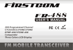
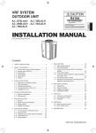
安装说明书
网络转换器
English
NETWORK CONVERTOR
For authorized service personnel only.
中 文
INSTALLATION MANUAL
MANUAL DE INSTALACIÓN
CONVERTIDOR DE RED
Sólo para personal de mantenimiento autorizado.
UTY-VLGX
MANUAL DE INSTALAÇÃO
CONVERSOR DE REDE
Apenas para técnicos de assistência autorizados.
PART NO. 9708436029
Español
ADAPTATEUR RESEAU
Uniquement réservé aux techniciens agréés.
Português
MANUEL D’INSTALLATION
Français
只适用于专业维修人员
INSTALLATION MANUAL
PART NO. 9708436029
NETWORK CONVERTOR
Contents
1. SAFETY PRECAUTIONS… ………………………………1
2. MAIN UNIT AND ACCESSORIES… ……………………1
3. ELECTRICAL REQUIREMENT……………………………2
4. SELECTING AN INSTALLATION LOCATION… ………2
4. 1. Dimensions… ………………………………………2
5. WIRING… ……………………………………………………2
5. 1. Wiring method… ……………………………………3
6. INSTALLING THE NETWORK CONVERTOR… ………4
6. 1. Connecting the power supply cable………………4
6. 2. Connecting the transmission cables………………4
7. TURNING ON THE POWER………………………………5
8. ADDRESS SETTING… ……………………………………5
9. INITIAL SETTING (SOFTWARE)…………………………6
▪▪ Area that generates substances that adversely affect the
equipment, such as sulfuric gas, chlorine gas, acid, or
alkali. It will cause the copper pipes and brazed joints to
corrode, which can cause refrigerant leakage.
▪▪ Area containing equipment that generates electromagnetic interference. It will cause the control system to
malfunction, preventing the unit from operating normally.
▪▪ Area that can cause combustible gas to leak, contains
suspended carbon fibers or flammable dust, or volatile
inflammables such as paint thinner or gasoline. If gas
leaks and settles around the unit, it can cause a fire.
▪▪ Do not use the unit for special purposes, such as storing
food, raising animals, growing plants, or preserving precision devices or art objects. It can degrade the quality
of the preserved or stored objects.
▪▪ Install the unit in a well-ventilated place avoiding rains
and direct sunlight.
Do not operate this unit when your hands are wet. Touching the unit with wet hands will cause an electric shock.
If children may approach the unit, take preventive measures so that they cannot reach the unit.
10. BINDING & COMMISSIONING (NOTICE)… ……………6
11. LED DISPLAY (D19)…………………………………………6
CAUTION
111 SAFETY PRECAUTIONS
▪▪ The “SAFETY PRECAUTIONS” indicated in this manual
contain important information pertaining to your safety.
Be sure to observe them.
▪▪ Request the user to keep this manual on hand for future
use, such as for relocating or repairing the unit.
WARNING
This mark indicates procedures which,
if improperly performed, might lead to
the death or serious injury of the user.
Perform electrical work by an authorized service personnel in accordance with this manual and the electrical
wiring regulations or implementation regulations of the
country. Also do not install this unit by yourself. Improper
electric work will cause electric shock or a fire.
Perform installation work in accordance with this manual.
Request an authorized service personnel to perform installation work. Do not install this unit by yourself. Improper installation will cause injury, electric shock, fire, etc.
In the event of a malfunction (burning smell, etc.), immediately stop operation, turn off the electrical breaker, and
consult authorized service personnel.
Install a leakage circuit breaker to power supply cable
in accordance with the related laws and regulations and
electric company standards.
Use a power source exclusively for this unit. Never share
the power source with other electrical equipment. Doing
so will cause fire and electric shock.
Do not install the unit in the following areas:
▪▪ Do not install the unit near a source of heat, steam, or
flammable gas.
▪▪ Area filled with mineral oil or containing a large amount
of splashed oil or steam, such as a kitchen. It will deteriorate plastic parts, causing the parts to fail or the unit to
leak water.
En-1
This mark indicates procedures which,
if improperly performed, might possibly
result in personal harm to the user or
damage to property.
Pay abundant care when transporting this unit because it
is a precision device. Improper transportation will cause
trouble.
Do not touch the switches with sharp objects. Doing so will
cause injury, trouble, or electric shock.
Do not expose this unit directly to water. Doing so will
cause trouble, electric shock, or heating.
Do not set vessels containing a liquid on this unit. Doing
so will cause heating, fire, or electric shock.
Dispose of the packing materials safely. Tear and dispose
of the plastic packing bags so that children cannot play
with them. There is the danger of suffocation if children
play with the original plastic bags.
Do not insert articles into the slit parts of this unit. Doing
so will cause trouble, heating, or electric shock.
222 MAIN UNIT AND ACCESSORIES
Important: Please print manual other than the installation
manual from attached CD-ROM before starting
the installation work.
The following installation parts are supplied. Use them as
required.
Name and Shape
Q’ty
Application
Main unit
Network convertor
1
Installation manual
This manual
1
Binder
3
For mounting the power
supply cable and
transmission cable.
Screw (M4 x 20 mm)
For mounting the Network
Convertor.
4
CD-ROM
For initial setting.
1
For initial setting tool and
manuals.
Connector cable
1
For connecting the power
supply cable.
(Except in U.S.A. and
Canada)
1
333 ELECTRICAL REQUIREMENT
Power
supply
cable
Size
Wire type
1.25 mm2
(16AWG) Type 60245
IEC 57 or
0.5 mm2 equivalent
Minimum
(20AWG)
Maximum
Transmission
cable
0.33 mm2
(22AWG)
Fuse capacity
3A
0–46 (32–114)
-10–60 (14–140)
0–95 (RH); No condensation
67 x 288 x 211 (2-5/8 x 1111/32 x 8-5/16)
1500 (53)
555 WIRING
WARNING
Dust proof bushing
Use
Temperature Operating
°C(°F)
Packaged
Humidity (%) Packaged
Dimensions
H x W x D mm(in.)
Weight g (oz.)
22AWG LEVEL4 (NEMA)
nonpolar 2
core, twisted
pair solid core
Shielded
Remarks
1Ø AC208–240 V
50/60Hz, 2 Cable +
earth (ground)
[Always earth
(ground) the unit]
LON WORKS
compatible cable
** LON WORKS is registered trademark of Echelon Corporation in the United States and other countries.
444 SELECTING AN INSTALLATION LOCATION
Before starting installation work, turn off the power of this
unit and the connection destination. Do not turn on the
power again until installation is completed. Otherwise, it
will cause electric shock or fire.
Use the accessories or specified power supply cable and
transmission cables. Do not modify power supply cable
and transmission cables other than those specified, do not
use extension cables, and do not use independent branch
wiring. Overcurrent may cause electric shock or fire.
Install the transmission cables securely to the terminal
block. Confirm that external force is not applied to the
cable. Use transmission cables made of the specified
cable. If intermediate connection or insertion fixing are
imperfect, it will cause electric shock, fire, etc.
When connecting the power supply cable and transmission cable, route the cables so that the cover of this unit
is securely fixed. If the cover is imperfectly fixed, it may
cause fire or overheating of the terminals.
Perform earth (ground) work positively. Do not connect
the earth (ground) cable to a telephone cable, water pipe,
or conductor rod.
Always fasten the outside covering of the transmission
cables with the cable clamp. (If the insulator is chafed,
electric leakage may occur.)
444444 Dimensions
Perform all wiring works so that the user does not touch
the wiring. Otherwise, injury or electric shock could result.
The Network Convertor is comprised of a body and cover.
If any cable is damaged, do not repair or modify it yourself. Improper work will cause electric shock or fire.
Unit : mm (in.)
89.5
(3-17/32)
89.5
(3-17/32)
2-Ø5 (3/16)
For M4x20mm
screws
95 (3-3/4)
Hole pitch
211 (8-5/16)
95 (3-3/4)
Hole pitch
Ø22.2 (7/8) For conduit
Ø28 (1-3/32)
For dust proof bushing
29
(1-5/32)
Ø28 (1-3/32)
For dust proof
bushing
241.6 (9-1/2)
272 (10-23/32) Hole pitch
288 (11-11/32)
4 - Ø5 (3/16) For M4x20mm screws
Power supply
Power consumption (W)
67
(2-5/8)
CAUTION
Do not bind the remote controller cable and the transmission cable together with or parallel to the power supply
cable of the indoor and outdoor units. It may cause erroneous operation.
When performing wiring work, be careful not to damage
the cable or injure yourself. Also, connect the connectors
securely. Loose connectors will cause trouble, heating,
fire, or electric shock.
Install the indoor and outdoor units, power supply cable,
transmission cable and remote control cable 1 m (40 in.)
away from television and radio to avoid distorted images
and noise. Otherwise, a malfunction could result.
Perform wiring so that water does not enter this unit along
the external wiring. Always install a trap to the wiring
or take other countermeasures. Otherwise it will cause
trouble or electric shock or fire.
1Ø AC208–240V
50/60 Hz
4.5
En-2
Confirm the name of each unit and name of each terminal
block of the unit and connect the wiring in accordance
with the directions given in the manual so that there is no
incorrect wiring. Incorrect wiring will damage the electric
parts and cause smoke and fire.
When installing the connection cables near a source of
electromagnetic waves, use shielded cable.
Otherwise, a breakdown or malfunction could result.
The terminal screws and earth (ground) screws have different shapes. Be sure to install the screws in the correct
locations. If the screws are installed in the wrong locations, the circuit board could be damaged.
555555 Wiring method
Note :
Router should be needed by the number of
controlling items in the BMS.
*1. Please do not make the connection like this
between VRF systems.
Maximum connectable indoor unit
number per 1 Network Convertor
Maximum connectable outdoor unit
number per 1 Network Convertor
Maximum connectable Network
Convertor number per 1 BMS
Maximum connectable Network
Convertor number per 1 VRF System
128
100
4
1
ELECTRICAL WIRING
PROPER SYSTEM DIAGRAM
General-purpose building control computer
(LONWORKS ® device)
TRANSMISSION
CABLE
Router
(Field supplied)
General-purpose
building control computer
(LONWORKS ® device)
Lighting
facilities
SWITCH (DISCONNECT SWITCH)
FUSE (3A)
POWER SUPPLY CABLE
NETWORK CONVERTOR
INDOOR UNIT
Security
system
LONWORKS ®
Network
POWER
SUPPLY
电 源
NO HIGH VOLTAGE
Automatic fire
alarm interface
X1 X2
1Φ 50/60Hz
208-240V
Y1 Y2 Y3
L
N
NO HIGH VOLTAGE
禁止
TRANSMISSION 信号线
LON
B1
VRF
B2
X1
X2
Ventilation
system
Outdoor unit
TRANSMISSION CABLE
Indoor unit
OUTDOOR UNIT
Network
Convertor for
LONWORKS ®
(UTY-VLGX)
NO HIGH VOLTAGE
X1 X2
Z1 Z2
H1 H2
INDOOR UNIT
MASTER
OR
SLAVE
OUTDOOR
UNIT
NO HIGH VOLTAGE
X1 X2
Y1 Y2 Y3
Network Convertor
Outdoor unit
VRF network system 1
*1
Indoor unit
Power supply cable
Transmission cable to
®
LONWORKS network
Network
Convertor for
LONWORKS ®
(UTY-VLGX)
Transmission cable to
VRF network
VRF network system 2
VRF
Outdoor unit
En-3
Indoor unit
Transmission cable
Router
(non-polar
(Field supplied)
2-conductor)
Note :
▪▪ Do not bind the power supply cable and transmission
cable to avoid an erroneous operation.
▪▪ Use shield cable for transmission cable.
The shield metal should be earthed (grounded).
▪▪ Do not forget to earth (ground) the Network Convertor.
▪▪ Install the disconnect switch to the easily accessible location.
▪▪ Install the fuse (3A) to the L line of power supply cable.
666 INSTALLING THE NETWORK CONVERTOR
WARNING
Always use the accessories and specified installation
work parts. Check the state of the installation parts. Not
using the specified parts will cause units to fall off, water
leakage, electric shock, fire, etc.
Install at a place that can withstand the weight of the unit
and install positively so that the unit will not topple or fall.
(((( Make a hole in the center of the dust proof bushing with the Phillips head screwdriver.
(((( Pass the power supply cable through the hole
of dust proof bushing and pull it into the network
convertor.
(((( Connect the power supply cable to their respective terminal block and the earth (ground).
(((( Securely tighten the binder and then confirm that
the cable will not come out.
Dust proof
bushing
When installing this unit, make sure that there are no children nearby.
Otherwise, injury or electric shock could result.
Install a circuit breaker.
Otherwise, electric shock or fire could result.
Knockout hole
Power supply cable
Binder
Cable
Binder
CAUTION
Before opening the cover of this unit, completely discharge static electricity charged on your body. Otherwise,
failure or malfunction could result.
Cut
Do not touch the circuit board and circuit board parts
directly with your hands.
Otherwise, injury or electric shock could result.
Binder clamp
Earth (Ground)
Tightening the mounting screws too tight will damage the
body of this unit.
Be careful so that the cover does not fall after the cover
screws are removed.
Otherwise, injury could result.
666666 Connecting the power supply cable
for U.S.A. and Canada
(((( Remove the 4 screws (M4 × 6 mm), and then
remove the cover.
(((( Install the conduit.
(((( Fix the conduit with lock nut.
(((( Pass the power supply cable through the conduit.
(((( Connect the power supply cable to their respective terminal block and the earth (ground).
(((( Securely tighten the binder and then confirm that
the cable will not come out.
Conduit (Power supply cable)
[Trade size: 1/2 in.]
Knockout hole
Lock nut
Power supply cable
Tightening torque for installing cables to terminal block
0.8 to 1.2 N • m (7.1 to 10.6 lbf • in)
666666 Connecting the transmission cables
(((( Turn the power off.
(((( Make a hole in the center of the dust proof bushing with the Phillips head screwdriver.
(((( Pass the transmission cables through the hole
of dust proof bushing and pull it into the network
convertor.
(((( Connect the transmission cables to their respective terminal block properly.
(((( Securely tighten the binders and then confirm
that the cable will not come out.
(((( Once the wiring of the cables has been completed, mount the cover to the network convertor.
Use the screws (M4 × 6 mm) to mount the cover.
(((( Use the 4 screws (M4 × 20 mm) provided to
mount the network convertor to the behind ceiling, wall, floor or other suitable location.
Dust proof bushing
Transmission cable
Binder
to VRF Network
Binder
Cable
Cut
Transmission cable to
LONWORKS ® Network
Binder
Cut
NO HIGH VOLTAGE
TRANSMISSION
LON
Binder clamp
B1
Earth (Ground)
VRF
B2
X1
X2
NO HIGH VOLTAGE
TRANSMISSION
LON
for Others
(((( Remove the 4 screws (M4 × 6 mm), and then
remove the cover.
(((( Open the knockout hole, and then install dust
proof bushing. If small animals such as insects
and dust enter this unit, a short circuit may be
caused.
B1
VRF
B2
X1
X2
Cable
Binder
Binder clamp
En-4
Tightening torque for installing cables to terminal block
0.8 to 1.2 N • m (7.1 to 10.6 lbf • in)
777 TURNING ON THE POWER
CAUTION
Check that the power supply voltage is within the specified
range. If the power supply voltage outside the specification is input, it will cause trouble.
Recheck the wiring. Incorrect wiring will cause trouble.
(((( Check the Network Convertor wiring.
(((( Check the wiring and switch settings for the VRF
system and turn on the power for the VRF system. For the wiring and switch setting method,
refer to the installation manual of each unit.
(((( Set the Jumper switch 1 (JP1) in order to set “Back
up battery ON”. (Fig.)
(This is necessary in order to save the initial setting data and commissioning data to SRAM.)
Fig.
BATTERY ON
BATTERY_ON
BATTERY OFF
BATTERY_ON
(((( Turn on the power for the Network Convertor.
Note:In procedure (3), the purpose of setting Jumper switch
(JP1) is to make the backup battery effective. The
backup battery can save the Tool for Network Convertor and Network Integration Tool setting information.
Therefore, it is not necessary to keep effective before
those setting works are done.
▪▪ The Network Convertor is initialized for a period of approximately a few seconds after the power is turned on.
is displayed on D19 during this period.
▪▪ After initial setting completely, the operation mode will be
started.
▪▪ Anyone of the following indication will displayed:
: VRF Network address allocation is not registered by using Tool for Network Convertor
D14
D14
888 ADDRESS SETTING
▪▪ Setting up more than 1 Network Convertor in 1 VRF network system is prohibited.
▪▪ When setting address, please be sure that the address
of Network Convertor is not overlap the address of other
controller like, Touch Panel Controller & Network Convertor for Group Remote Controller.
SWITCH POSITION
SW1
D19
JP1*
SW7
SW2
SW3 SW4
This is “Service Pin”.
Neuron ID is sent upon pushing BMS
service switch (SW2)
Following steps are necessary for setting address of Network Convertor.
111Turn on the power of Network Convertor.
222Select the special mode by pressing and releasing
SW7 (reset button) while holding down SW4 (set button) until special mode “1” (Blinking) is displayed.
Please keep holding down SW4 (set button) a few
seconds after releasing the SW7 (reset button).
When SW3 (mode button) is pressed, special mode
changes from ‘1’ to ‘4’ (Blinking) as the as shown in the
above mentioned way.
333Press SW3 (mode button) to set special mode “2”.
Special mode “2” is the address setting mode.
444Press SW4 (set button). Present address is displayed.
Ex.) Address No.15
: Binding and Commissioning is not executed
: Normal Mode (Ready for operation)
: Others (Refer to “11. LED DISPLAY (D19)” for
more detail.)
** Network Convertor does not operate during initialization.
** If an error occurs, the D9 or D14 LED lights or flashes,
or the error code is displayed on the right side of the D19
LED display.
555Press SW3 (mode button) to select the address.
The displayed address changes as follows each time
the mode button is pressed.
A00
A01
A02
A15
Ex.) A
ddress No.3
is selected.
666Press SW4 (set button) to set the selected address.
Ex.) Address No.3 is set.
En-5
777Turn the power off and on or press SW7 (reset button)
to exit from address setting mode.
This time, please refer to the “7. TURNING ON THE
POWER” for the content displayed in D19 LED.
1111LED DISPLAY (D19)
(1) Normal code
Normal code
Contents
Normal mode
999 INITIAL SETTING (SOFTWARE)
Set state of “Tool for Network Convertor”
The initial settings for the Network Convertor must be performed before the commissioning. Please see the attached
“Application Manual - Tool for Network Convertor” and
complete the settings.
Address setting mode
Under maintenance
1111BINDING & COMMISSIONING (NOTICE)
(((( It is necessary to make an XIF (External Interface
File) for binding.
(((( The commissioning doesn’t end if the number of
Indoor/Outdoor Unit of the XIF file made with Tool
of Network Convertor is not in consistency with
the number after Indoor/Outdoor Unit Address is
registered.
In addition, the Network Convertor can not operate normally if the number of Indoor/Outdoor Unit
of the XIF file is not in consistency with the number after Indoor/Outdoor Unit Address is registered.
(((( Binding and commissioning must be performed
again if the number of connecting units (indoor/
outdoor units) has changed after system operation. Please always register the allocation
information that is in consistency with the VRF
system, Functional Block in the Network Convertor and the Network Convertor, if register the
changed XIF file in according to the “Tool for
Network Convertor”.
Important:
Network Convertor will not operate if,
▪▪ VRF network system address (Indoor & Outdoor units address) allocation information are not registered to Network Convertor.
▪▪ XIF data information and VRF network system address
allocation information must not be same.
▪▪ Binding & Commissioning is not executed.
▪▪ The ID number registered on Network Convertor is different from the ID number when XIF file is created.
▪▪ Two or more Network Convertors are connected to BMS,
and these are set the same ID number.
FB and unit address allocation
information is registered with
“Tool for Network Convertor”
FB* : Functional Blocks
(2) Error code
Error code
Contents
FB and unit address allocation
information is not registered
Main PCB error
VRF Network error
D9 LED lit or blinking
D9
D9
D14 LED lit or blinking
D14 D14
Communication error
(Error of the Network Interface Device on VRF System)
Communication error
(Error of the Network Interface Device on BMS)*1
When V series or S series is connected
**** D14 is ON for 1 second, OFF for 1 second, and repeats. When
D19 is in Normal mode, Commissioning is unset.
En-6