1
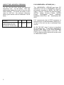
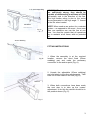
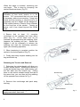
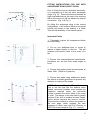
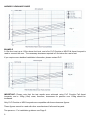
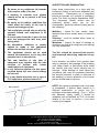
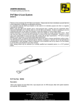
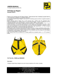
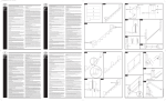
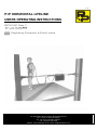
v1 11/05
P+P HORIZONTAL LIFELINE
USERS OPERATING INSTRUCTIONS
EN795:1997 Class C
Supplied by Pammenter & Petrie Limited
PAMMENTER & PETRIE LIMITED
140-146 Brearley Street. Hockley, Birmingham B19 3XJ
Tel: +44 (0) 121 359 4561 (Sales)
Tel: +44 (0) 121 503 5860 (Training)
Fax: +44 (0) 121 359 4136
Website: www.pammenter.co.uk E-mail: [email protected]
USE OF THE LINE WITH 2 PERSONS
P+P HORIZONTAL LIFELINE (HLL)
The HLL has also been tested and approved
two-person use - for fall arrest. This was
achieved by loading the centre of the line with
26kN (2650kg). To ensure the safety of two
users on the HLL, the minimum clearance
values given below must be adhered to at all
times.
The HORIZONTAL LIFELINE has been CE
marked by P+P Ltd to 89/686/EEC using the
procedures described in BSEN 795:1997 for
class C devices. Certified by Approved Body:
SATRA, Safety Product Centre, SATRA
House,
Rockingham
Road,
Kettering,
Northants, NN16 9JH, UK. Identification No:
0321.
HLL position above user’s
foot level
MINIMUM clearance
required below user’s feet.
Ensure that anchor points
are adequate, at least 30kN.
P+P recommends that all PPE equipment is
personal issue, all documentation relating to it,
is kept on file until the item is withdrawn from
service.
2.0m
1.25m
0.0m
8.0m
8.75m
10.4m
An EN 795:1997 class C device is described
as an anchor line. It has been subjected to
dynamic tests using a non shock absorbing
lanyard and a 100kg mass in a 4m fall. The
P+P line has also been tested with a static load
of 36kN without failure.
2
P+P Anchorage Sling
IMPORTANT: It is vital that anchor points
are sufficiently strong, they should be
capable of withstanding a minimum of 15kN
horizontally and in the direction of the line.
The high anchor rating is due to the vector
forces generated in the high angle ‘Y’ formed
in the line when loaded.
Karabiner
Fig. A
NOTE: When used as an anchor for a restraint
system – as opposed to fall arrest – then more
than one operative can use the line at one
time. You must be certain that all operatives
are in restraint at all times, with no potential
fall.
35mm Webbing
FITTING INSTRUCTIONS
Fig. B
1. When the assembly is at the required
location, remove the short fixed (50mm
webbing) part and make the necessary
connection to the anchor point (Fig. A).
2. Unpack the adjustable (35mm webbing)
part and attach to the other anchor point. Take
care not to have twists in the line (Fig. B).
Ratchet
3. When both connections have been made
the next step is to take up the ‘coarse’
adjustment, to do this the ratchet should be in
the position shown (Fig. C).
Fig. C
3
When this stage is reached, tensioning can
now begin. This is done by ‘plumping’ the
ratchet handle as shown (Fig. D).
NOTE: On pre-2004 models there is no
indication of how much tension is in the
system. P+P recommend that only one hand
is necessary without over exerting. Using both
hands and over exerting, or using a lever is not
necessary and at a height can be dangerous.
2004 models feature a Tension Force Indicator
on the fixed bar of the ratchet. Tension as
above, until it has closed beyond the 250dN
mark.
Indicator
Spreader Bar
Fig. D
4. Ensure that at least 1½ complete
revolutions of the spreader bar have taken
place (Fig. D). At the same time do not
overload the spreader bars with webbing, if this
happens, the webbing will jam. Should this
happen it will be necessary to release the
webbing and start the tensioning operation
again (see releasing operation).
5. When tensioning is complete, position the
ratchet in the locked position (Fig. E).
6. Finally pack away surplus webbing into the
bag and buckle up.
Fig. E
Releasing the Tension and Removal
7. Releasing the ratchet handle will allow you
to open up the ratchet. Allowing the ratchet to
re-grip the ratchet ring under slight tension, pull
the ‘tab’ back from the ratchet ring. Pulling
back on the ratchet release handle and tab at
the same time, you can then pull the webbing
off the spreader bar as shown in Fig. F.
8. Remove from anchorage and pack away
into bag.
Ratchet Ring
Release Tab
Ratchet Release
NOTE: A neatly packed bag will aid easy
deployment when next used.
4
Fig. F
FITTING INSTRUCTIONS FOR USE WITH
ANCHORAGE SLING (90287 / 90302)
Prior to fitting the line as described previously,
it is necessary to fit the two other anchorage
slings (Fig. G). These should be positioned as
high as possible above the user, thus ensuring
that in the event of a fall the distance is kept to
a minimum. (Fig. H & Fig. I).
P+P Anchorage Sling
Fig. G
By fitting the anchorage sling in the correct
configuration, it will ensure that the Horizontal
Lifeline will remain in the position it is fitted.
This will aid assembly of the overall system.
Important Points
1. Thoroughly inspect all components before
and after fitting.
2. Do not use additional bars or levers to
induce a higher tension in the line. This will
increase end anchor loads in the event of a
fall.
3. Ensure that harness/lanyard attachments,
karabiners etc. are free from sharp edges or
burrs.
Fig. H
4. Ensure that anchor points are adequate, at
lease 15kN. (30kN for 2 persons).
5. Ensure that when using attachment straps
the sleeve is suitably positioned to prevent any
abrasion or cutting of the straps.
Fig. I
NOTE: Clearance Required Below User
Due to the fact that the line deflects when
loaded, users and installers must consider the
clearance required below the Horizontal
Lifeline to ensure the users’ safety in the event
of a fall. The danger to the user can be greatly
reduced if the line is installed at head height,
and/or shorter lanyards are used to connect.
These factors combine to reduce the graph on
the next page, which explains the safe
clearance X when used with P+P Chunkie or
NRG Fall Arrest Lanyards (Fig. H, I, J and K).
5
HAZARD CLEARANCE GUIDE
Fig. J
EXAMPLE
A 15m line is set up at 1.25m above foot level, and a 2m P+P Chunkie or NRG Fall Arrest Lanyard is
used to connect the user. The necessary clearance required is 5.2m below the user’s feet.
If you require more detailed installation information, please contact P+P.
Fig. K
IMPORTANT: Please note that the test results were achieved using P+P Chunkie Fall Arrest
Lanyards, and a 100kg (16st) mass, therefore, clearances for persons over 100kg should be
increased.
Only P+P Chunkie or NRG Lanyards are compatible with these clearance figures.
These figures cannot be used with other manufacturers’ fall arrest lanyards.
Two persons – For installation guidance see Page 2.
6
WARNINGS:
INSPECTION AND EXAMINATION
1. Be aware of any additional fall hazards
at the anchor ends of the line.
Keep these instructions, or a copy with the
Horizontal Lifeline to aid future inspection and
examination. Examination by a competent
person at intervals of 6 months is mandatory
under The Work at Height Regulations 2005.
The Horizontal Lifeline should also be
examined before every use by the
user/installer, particular attention being paid to
the following:-
2. If working in restraint your system
should be set up to prevent a fall from
occurring.
3. Be aware of all medical conditions that
could affect the safety of the user in
normal and emergency use.
4. This equipment should only be used by
persons trained and competent in its
safe use.
5. A rescue plan should be in place to deal
with any emergencies that may arise
during work.
6. No alterations, additions or repairs
should be made to this equipment
without the written consent of P+P.
7. The equipment should not be used
outside the limitations, or for any other
purpose that it is intended for.
8. The safe function of one item of
equipment may interfere with the safe
function of another with certain
combinations of equipment.
9. In any fall-arrest system, the free space
required below the user should always
be ensured.
10. If in any doubt about the use or care of
P+P equipment, please contact P+P.
Black Thread
Webbing – check for cuts, cracks, tears,
abrasion and scorch marks, burns or chemical
attack
Stitching – Look for broken stitch, loose or
worn threads.
Metalware – Inspect for signs of damage or
distortion and that all moving parts and springs
are fully operational.
The HLL should be removed from service
and inspected after being subjected to any
fall.
Local abrasion as distinct from general wear
may be caused by the passage of the webbing
over sharp edges or protrusions while under
the tension and may cause serious loss of
strength. Slight damage to outer fibres and
occasional yarn may be considered harmless
but serious reduction in width or thickness of
the webbing or serious distortion to the weave
pattern should lead to rejection.
NOTE: As a guide to establish how much wear
is acceptable, a distinct black thread of a
different construction, is woven into the
selvedge of the black webbing. (Fig. L). When
this becomes clearly visible, it should be
inspected and refurbished by P+P, for further
details of the level of service in your area
contact your supplier.
PAMMENTER & PETRIE LIMITED
140-146 Brearley Street. Hockley, Birmingham B19 3XJ
Tel: +44 (0) 121 359 4561 (Sales)
Tel: +44 (0) 121 503 5860 (Training)
Fax: +44 (0) 121 359 4136
Website: www.pammenter.co.uk E-mail: [email protected]