1
1205/1206 CUTTER
SECTION 1
Operating
Instructions
I
SSUE 1
UNE 1993
J
Page 1 - 1
1205/1206 CUTTER
1.1.1 TECHNICAL SPECIFICATION
1205
Form sizes
Width5" to 17 1/2" (127mm to 445mm)
Depth2" to 99 5/6" / 99 7/8" (51mm to 2536mm / 2537mm)
Strip Cut 1/6"/1/8" to 3 5/6"/3 7/8" (4.2mm/3.2mm to 97mm/98mm)
Form weights
All standard commercially available stock
from flimsy papers to heavy card and up to
6 part sets, including carbon interleaved and
self copying papers.
Weight Range: Min. - 55 gsm (15 lbs bond)
Max. - 400 gsm (106 lbs bond)
Fixed Operating Speeds (forms per hour)
Without strip cut
With strip cut
4" deep forms 9,000
4" deep forms 6,000
6" deep forms 8,000
6" deep forms 5,000
8" deep forms 6,500
8" deep forms 4,500
12" deep forms 5,000
12" deep forms 4,000
Programmable memory
Capacity for 20 programs
1206
As 1205 above except:
Variable Operating Speeds - up to (forms per hour)
Without strip cut
With strip cut
4" deep forms 12,500
4" deep forms 8,000
6" deep forms 10,800
6" deep forms 7,300
8" deep forms 9,800
8" deep forms 6,900
12" deep forms 8,000
12" deep forms 6,000
Programmable memory
ISSUE 3
DEC 2003
Capacity for 30 programs
Page 1 - 2
1205/1206 CUTTER
1.1.2 MACHINE LAYOUT DIAGRAM
I
SSUE 1
UNE 1993
J
Page 1 - 3
1205/1206 CUTTER
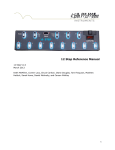
1.1.3 CONTROL PANEL LAYOUT
LED's
Program Number
6th or 8th Selection
Program Display
Select up Button
Form Depth
Strip Depth
Preselect Speed
(1206 only)
Mode Button
Select down Button
Fine Adjust Forward
Auto Feed/First Form
FIne Adjust Back
Speed increase Button
(1206 only)
Selected Speed
(1206 only)
Speed decrease Button
(1206 only)
Continuous Button
Stop Button
NOTE: THIS MANUAL COVERS THE OPERATION OF BOTH 1205 (FIXED
SPEED) AND 1206 (VARIABLE SPEED) CUTTERS. WHERE APPLICABLE,
THE DIFFERENCES ARE INDICATED THROUGHOUT.
I
SSUE 1
UNE 1993
J
Page 1 - 4
1205/1206 CUTTER
1.2.1 MACHINE OPERATION
1.
Plug in machine (at plug point by power switch) and lift top cover.
Load stationery on tractors
To set tractor position, release tractor grip levers and slide tractors inwards or outwards
to accommodate stationery onto pins. Ensure that stationery is neither too tightly stretched,
nor too loose between tractors. Position stationery so that the leading edge is just covering the
sensor in the RH tractor unit (see inset view on Machine Layout Diagram). When satisfied,
lower tractor tops and lock grip levers.
2.
3.
Set trimmer position
To set trimmer position, release trimmer grip levers and slide trimmers across until cut
position indicator aligns with the horizontal position on the form where the desired cut is to be
made (see inset view on Machine Layout Diagram). This position is normally slightly inboard
of the form perforations.
To assist alignment, it may be helpful to manually wind the form forward by turning the splined
tractor shaft. This will move the leading edge closer to the cut position indicator. If this is
done, ensure that the form is moved back to its original position of just covering the sensor.
Note: power must be OFF in order to manually turn shaft.
4.
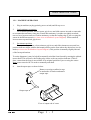
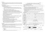
Attach output tapes as shown below:
Remove covering on adhesive tape
on underside of bracket and attach
output tape.
Output tape
View of output end of cutter
I
SSUE 1
UNE 1993
J
Page 1 - 5
1205/1206 CUTTER
5.
Lower top cover and switch on machine. No motors will run at this stage, and the machine will display a start-up greeting "HI" on the display panel. This will last for about 3 seconds, and then change to indicate the last used program number ("Pn").
6.
Select desired program by pressing 'select up' (+) or 'select down' (-) buttons. See section
1.2.2 for further details on Program Selection.
7.
Press Auto feed/First form button to feed and cut the first form.
8.
Set magnetic paper stops on output tray to accommodate the cut form size.
9.
Feed a single form onto the output tray. This is done by pressing and holding the 'Stop'
button and then simultaneously pressing the 'Continuous' button once. Check that the paper
stops are in the right place on the output tray, and that the cuts are in the correct position.
10. If the horizontal cut is occurring in the wrong position, this can be adjusted forwards or
backwards by pressing the 'Fine adjust' buttons. The amount of displacement will be shown on
the display panel in units of 1/96". Default is "00", one increment forward will show "01" and
one increment back will show "-01". The fine adjustment applies equally to single or strip cut.
11. Press 'Continuous' button, and stationery will run through the machine, delivering the cut
forms onto the output tray.
1206 only: speed may be varied at this stage by pressing the 'Speed increase/decrease' buttons.
When required, press 'Stop' button to halt continuous run.
12. When the last form of the run enters the machine, it will be processed onto the output
tray and the machine will recognise that there are no more forms to follow. No further cuts will
be made.
13.
Switch off machine and unplug mains supply when work is complete.
Note:
If the machine is switched on and remains idle for more than one minute, the main
drive motor will automatically be powered down.
I
SSUE 1
UNE 1993
J
Page 1 - 6
1205/1206 CUTTER
1.2.2 OPERATOR PROGRAM INSTRUCTIONS
The machine may be programmed with up to 30 programs (1206) or 20 programs (1205). The
first 10 are factory set, and the settings for each are shown below.
PROGRAM No.
1
2
3
4
5
6
7
8
9
10
FORM DEPTH
STRIP CUT
4"
8"
11"
11 4/6"
12"
4"
8"
11"
11 4/6"
12"
NO
NO
NO
NO
NO
YES
YES
YES
YES
YES
The desired program is selected after switching on the machine and after the "HI" startup
message has been replaced by the number of the last used program. Press program 'Select up/
down' buttons to the required number. You may define your own program settings for numbers 11 - 30 (1206) or 11 - 20 (1205), as described below and overleaf. Programs 1 - 10 can
also be changed and overwritten if desired.
1.2.3 USER DEFINED PROGRAM SETTING
To define settings for programs 1-30 (1206) or 1-20 (1205), initially set the Program number
to that desired by pressing the 'Select up' button after start-up. The number will flash if not
currently programmed. Refer to control panel detail below for the controls used throughout
this section.
LED's
Program Number
6th or 8th Selection
Program Display
Select up Button
Form Depth
Strip Depth
Preselect Speed
(1206 only)
I
SSUE 1
UNE 1993
J
Mode Button
Select down Button
Page 1 - 7
1205/1206 CUTTER
Press 'Select up' (+) and 'Select down' (-) buttons together and hold down for 5 seconds. The
Program number LED will begin flashing, and the selected program number on the Display
panel which was previously flashing (if not previously programmed) will become static.
Press the 'Mode' button and the 6th or 8th selection LED will begin flashing. Press 'Select up'
(+) or 'Select down' (-) button to set 6th's or 8th's, as indicated on the Display panel. This
refers to units in either 6th's or 8th's of an inch.
Press the 'Mode' button again and the Form depth LED will begin flashing. Press 'Select up' (+)
or 'Select down' (-) button to set the desired form depth. The Display panel will indicate whole
inches followed by the selected units, either 6th's or 8th's, eg. 8.5 would indicate 8 5/6" if 6th's
were selected.
Press the 'Mode' button again and the Strip depth LED will begin flashing. Press 'Select up' (+)
or 'Select down' (-) button to set the desired strip depth, ie. the total depth of the strip that will
encompass the perforation. The Display panel will indicate the strip depth in the selected units,
eg. 0.1 would indicate 1/6" if 6th's were selected. The initial value is 0.
1206 only: Press the 'Mode' button again and the Preselect speed LED will begin flashing.
Press 'Select up' (+) or 'Select down' (-) button to set the desired speed, which will be indicated
in the Display panel. Note that this setting can be overidden at any time during operation by
pressing the 'Speed increase/decrease' buttons.
Press the 'Mode' button again and the selected program number will be shown on the Display
panel. The program is now entered into memory and will remain at these settings unless it is
overwritten. The memory otherwise remains intact even after the mains supply is disconnected.
Programs 1-30 (1206) or 1-20 (1205) can be re-programmed at any time. Note that if 1-10 are
re-programmed and it is later desired to reset to default programs, these can all be simultaneously reset by the use of Engineer Test Mode 4. See section 2.4 of this manual for further
details.
The settings of all programs (1-20/30) can be confirmed by stepping through with the 'Mode'
button with the program number indicating on the Display panel. The display will show:
1)
3)
3)
4)
I
SSUE 1
UNE 1993
J
Whether 6th's or 8th's selected
Form depth
Strip cut depth (if selected)
Preselected speed (1206 only)
Page 1 - 8
1205/1206 CUTTER
PROGRAM SETTING FOR TRIM ONLY
It is possible to set the machine for trimming only, with the cutter blade de-activated. To do
so, select an unused or redundant program number and program as below:
1.
Set for either 6ths or 8ths
2.
For form depth, press and hold 'Select up' (+) button until display reaches
99.5 (or 7). The next position gives a display of '--.-' and is the required setting.
3.
Set strip cut depth to 0
4.
Set desired speed (1206 only). A low initial speed setting is recommended.
The program is now set for trim only, and the cutter blade will not operate.
I
SSUE 1
UNE 1993
J
Page 1 - 9