1
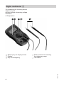
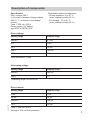
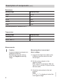
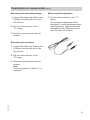
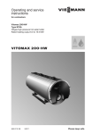
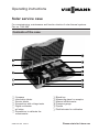
Operating instructions
Solar service case
For commissioning, maintenance and function checks of solar thermal systems
Part no. 7248 299
Contents of the case
A Compass
B Information labels
C Service labels
D Screwdriver with voltage tester
E Digital multimeter
F pH strips
G Screwdriver to calibrate the
refractometer
5592 557 GB 7/2013
H Bleed key
K Measuring glass for samples
L Manual refractometer
M Pressure gauge
N Pipette
O Distilled water for calibration
Please retain for future use1
Compass A
For aligning the collectors.
Turn the compass capsule so the red
tip of the needle settles between the
two green markers. The red tip will then
be pointing north.
Information label B
Affix the information label close to the
filling facility to prevent the system
being filled with water.
Service label C
Affix the service label where it can
easily be seen by the system user, e.g.
on the solar station, solar control unit or
DHW cylinder.
This will remind the system user of the
next service date.
Screwdriver D
For a quick voltage check at the
solar control unit or other electrical
components.
pH strips F
For checking the pH value of the heat
transfer medium.
5592 557 GB
1. Using measuring glass K, remove
some heat transfer medium from the
system.
2. Briefly dip the test strip into the
sample and determine the pH value
using the scale on the box. The heat
transfer medium is still OK if the pH
value lies between 10.0 and 8.5. At
values below 7.5, replace with fresh
heat transfer medium.
2
Pressure gauge M
For checking the pre-charge pressure
of the expansion vessel.
Charge pressure of the expansion
vessel:
0.7 bar + 0.1 x static head.
Measuring range:
0 to 600 kPa (0 to 6 bar).
Prior to commissioning, the needle
should point to 0 kPa. If this is not the
case, press the button at the side until
the needle settles on 0 kPa.
Manual refractometer L
For determining the frost protection
temperature of the heat transfer
medium (water propylene glycol, water
ethylene glycol).
Cloud point
An antifreeze mixture does not
freeze immediately when it cools
down to freezing point. At a certain
temperature (cloud point), the mixture
starts to form ice crystals. The fluid
becomes increasingly viscous, and at a
correspondingly low temperature (pour
point) freezes completely.
nD20 (calculation index)
5592 557 GB
This allows you to determine various
parameters of liquids if you have the
corresponding tables of variables.
3
Manual refractometer L
P Cover for spreading the heat
transfer medium
R Prism surface
S Calibration 0 line
(set at the factory)
T Eyepiece
1. Using pipette N (see illustration
on page 1), squeeze one or two
drops of the test fluid onto the prism
surface.
2. Close cover P and apply light
pressure.
3. Hold the refractometer up to the light.
5. Refer to this boundary to find the
temperature of the cloud point and
the calculation index.
4
5592 557 GB
4. Turn eyepiece T until boundary X
is clearly visible.
Manual refractometer L (cont.)
Calibration (if required)
1. Using pipette N, squeeze two drops
of distilled water O (see illustration
on page 1) onto the prism surface.
2. Close cover P and apply light
pressure.
3. Hold the refractometer up to the
light.
4. Using small screwdriver G (see
illustration on page 1), set the
boundary to the waterline.
5592 557 GB
Notes on care of the device
Clean the prism surface with the cloth
supplied.
Never clean under running water.
5
Digital multimeter E
For measuring the following values:
■ Direct current
■ Direct voltage, alternating voltage
■ Resistor
■ Temperature
Y Rotary selector for selecting
the measuring range
Z Test cables
5592 557 GB
U Memory key for display screen
V Display
W Key for backlighting
6
Description of components
Specification
Max. voltage: 600 V
In the case of excess voltages (above
600 V), "1" is shown on the display
screen.
Fuse: F 200 mA / 250 V
Power supply: 9 V battery,
type 6F22 or NEDA 1604
Permissible ambient temperature
- During operation: 0 to 40 °C
(max. relative humidity 85 %)
- For storage: -10 to 50 °C
(max. relative humidity 85 %)
Direct voltage
Setting range
Display range
200 mV
0.1 mV
2 V
1 mV
20 V
10 mV
200 V
100 mV
600 V
1 V
Input resistance: 10 MΩ
Alternating voltage
Setting range
Display range
200 mV
100 mV
600 V
1 V
Frequency range: 40 to 400 Hz
5592 557 GB
Direct current
Setting range
Display range
2 mA
1 μA
20 mA
10 μA
200 mA
100 μA
10 A
10 mA
Fuse: F 200 mA / 250 V
Setting at 10 A not fuse protected
7
Description of components (cont.)
Resistance
Setting range
Display range
200 Ω
0.1 Ω
2 kΩ
1 Ω
20 kΩ
10 Ω
200 kΩ
100 Ω
2 MΩ
1 kΩ
Overload protection: effective 250 V
Temperature
Setting range
Display range
–30 to 400 °C
1 °C
400 to 1000 °C
1 °C
Measurements
!
Caution
Incorrect measuring ranges can
damage the device.
Before beginning the testing,
select the largest measuring
range.
Measuring direct current and
direct voltage
1. Connect the black test cable to the
COM port and the red one to the
VΩ mA port.
8
3. Guide the test probes to the test
location.
Note
If "1" or "–1" is displayed, select the
next highest range.
5592 557 GB
2. Set the rotary selector to the
required range.
With a direct current above 200 mA
(up to 10 A), use the 10 A port for the
red test cable.
Description of components (cont.)
Measuring the alternating voltage
Measuring the temperature
1. Connect the black test cable to the
COM port and the red one to the
VΩ mA port.
1. Set the rotary selector to the "°C"
range.
The ambient temperature will be
displayed. If using the thermocouple
(see illustration), connect the black
test cable to the COM port and the
red one to the VΩ mA port.
2. Set the rotary selector to the
"V~" range.
3. Guide the test probes to the test
location.
Measuring the resistance
1. Connect the black test cable to the
COM port and the red one to the
VΩ mA port.
2. Set the rotary selector to the
"Ω" range.
5592 557 GB
3. Guide the test probes to the test
location.
Note
If no measurement is taken, "1" is
displayed.
9
Description of components (cont.)
Continuity test
1. Connect the black test cable to the
COM port and the red one to the
VΩ mA port.
2. Set the rotary selector to the "+"
range.
3. Connect the test probes across
2 points in the power circuit. If the
resistance is lower than 50 Ω, you
will hear a sound signal.
Changing the batteries
5592 557 GB
The device is equipped with a 9 V block
battery.
Before changing the battery, disconnect
the device from the test location.
Open the battery compartment at the
back.
10
11
5592 557 GB
12
Viessmann Werke GmbH&Co KG
D-35107 Allendorf
Tel: +49 (0) 64 52 70-0
Fax:+49 (0) 64 52 70-27 80
www.viessmann.de
Viessmann Limited
Hortonwood 30, Telford
Shropshire, TF1 7YP, GB
Tel: +44 (0)1952 675000
Fax: +44 (0)1952 675040
Email: [email protected]
Subject to technical modifications
Contact your local heating contractor if you have any questions regarding the
maintenance and repair of your heating system.
Local heating contractors can be found on the internet, at www.viessmann.de.
5592 557 GB
Your contact