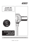
1
LP
Thermostatic
mixer shower
Installation and
operating
instructions
Installers
T00300
please note these instructions are to be left with the user
2180138M
June 2008
LP Thermostatic mixer shower
CONTENTS
Page
Introduction.................................................................................... 1
Safety warnings............................................................................... 1
Main components........................................................................... 2
Siting requirements......................................................................... 3
Preparing the mixer valve................................................................ 4
Siting of the shower........................................................................ 4
Fitting the shower to the wall - Exposed.......................................... 5
Rising and falling supplies........................................................ 5
Rear entry supplies................................................................... 8
Fitting the shower to the wall - Built-in.......................................... 11
Solid wall................................................................................ 11
Hollow wall............................................................................. 14
Shower cubicle or panel.......................................................... 16
Flushing procedure......................................................................... 18
Fitting the tamperproof fixed head - Exposed................................. 19
Fitting the tamperproof fixed head - Built-in.................................. 20
Fitting the fixed head - Built-in....................................................... 21
Fitting the bulkhead....................................................................... 22
Operating the shower.................................................................... 23
Adjusting the maximum temperature stop..................................... 24
Spare parts..................................................................................... 25
Fault finding................................................................................... 27
Guarantee, service policy, etc....................................................rear cover
To check the product suitability for commercial and multiple installations, please contact Triton’s
specification advisory service before installation.
Telephone: 0870 067 3767
Facsimile: 0870 067 3334
E mail: [email protected]
LP Thermostatic mixer shower
Introduction
INTRODUCTION
SAFETY WARNINGS
Safety warnings
This book contains all the necessary fitting and
operating instructions for your Triton low
pressure thermostatic mixer shower. Please read
them carefully.
a. Layout and sizing of pipework MUST be such
that when other services are used, pressures
at the shower control inlets do not fall below
the recommended minimum.
Please read through the whole of this book
before beginning your installation.
b. DO NOT choose a position where the shower
could become frozen.
The installation MUST be carried out by a
suitably competent person and in sequence of
this instruction book.
c. The outlet of this appliance MUST NOT be
connected to any form of tap or fitting not
recommended by the manufacturer.
Care taken during the installation will give a long
and trouble free life from your mixer shower.
d. The showerhead MUST be regularly cleaned
to remove scale and debris.
Thermostatic mixers will automatically maintain
your chosen temperature, even if taps are turned
on elsewhere in the house, and shut off if either
the hot or cold supply fails.
e. Conveniently situated isolating valves in each
inlet supply MUST be fitted as an
independent method of isolating the shower
should maintenance or servicing be necessary.
For the best performance within the specified
running pressure range a minimum flow of
eight litres per minute should be available to
both inlets.
f. If it is intended to operate the shower in areas
of hard water (above 200 ppm temporary
hardness), a scale inhibitor may have to be
fitted. For advice on the Triton scale inhibitor,
please contact Customer Service.
The mixer shower MUST NOT be subjected to
water temperatures above 80°C.
g. Do not operate the shower outside the
C-007-Aguidelines as laid out in ‘site requirements’.
This low pressure valve is suitable for use with
traditional low pressure gravity water systems,
using a cold water cistern and hot water cylinder.
Inlet connections are by compression fittings for
15 mm copper pipe.
This valve unit is supplied with a mounting
bracket to suit installation in a chased out cavity
in a solid wall, a stud partition wall, dry lined wall
or fixing to a shower cubicle or panel.
Replacement parts can be ordered from Customer
Service. See ‘spare parts’ for details and part numbers.
Y-003-A
LP Thermostatic mixer shower
MAIN
COMPONENTS (fig.1)
Main components
1. Inlet nuts and olives
9.Temperature knob
16.Flush mount plate
2. Inlet elbows
10.Knob trim
17.Flush mount cover
3. Valve housing
18.Trim ring
4. Outlet adaptor
11.Max. temperature override
button
5. Outlet nut and olive
12.Cover
20.Nut covers
6. Outlet blanking plug
13.Inlet trims
21.Pipe trims
7.Cartridge assembly
14.Outlet trim
22.Hexagonal nut
8. Flow knob
15.Outlet blanking trim
23.Shroud (flush fit only)
19.Cartridge fixing screws
Fig.1
5
1
4
16
2
3
1
7
18
17
19
2
6
11
8
19
19
20
20
9
10
23
13
14
20
21
13
22
12
15
T00301
18
LP Thermostatic mixer shower
Siting
requirements
SITE REQUIREMENTS
Fig.2 diagrammatic view (not to scale)
The installation must be in accordance with
Water Regulations/Bylaws.
Stop valve
Minimum running water pressure: 0.1 bar.
Maximum running water pressure: 1 bar.
Maximum static water pressure: 10 bar.
For the best performance within the specified
running pressure range a minimum flow of 8
litres per minute should be available to both
inlets.
Cold
water
mains
supply
While the mixer valve is operational (open
outlet), inlet pressures MUST NOT be capable of
exceeding one bar. For effective operation of the
internal seals, the maximum static pressure must
not be exceeded.
Cold water Cold supply
cistern
Alternative
1metre
supply
minimum
(must be
below
vent pipe tee)
Gate
Hot
valve
supply
Hot water
cylinder
The pipework should be installed such that the
flow is not significantly affected by other taps
and appliances being operated elsewhere on the
premises.
Drain
valve
Other
draw-offs
Fig.2 shows a typical gravity fed installation
where the hot water supply for the shower is
made via a tee connection on the underside of
the rising horizontal
section of pipework from the
D-004-A
cylinder. Alternatively, the connection can be
taken from the hot supply pipe to other outlets
as long as it is the first draw-off below the
ventilation pipe tee.
Draw-off must point
down to avoid airlock
issues
T00302
Note: The distance between the bottom of the
cold water cistern and the showerhead must be
at least one metre.
For effective thermostatic control the
temperature of the hot water entering the mixer
should remain a minimum of 10°C above the
selected output temperature.
DO NOT use jointing compounds on the
pipework.
Service
valve
Service
valve
Mixer
valve
LP Thermostatic mixer shower
PREPARING
MIXER
Preparing theTHE
mixer
valve VALVE
Fig.3 diagrammatic view (not to scale)
Before starting the installation, make sure all the
openings on the valve are carefully covered to
prevent ingress of any debris etc.
Note: It is not necessary to remove the control
knobs at any stage.
SITING
THE
SHOWER
Siting ofOF
the
shower
WARNING!
The shower must not be positioned
W-008-A
where it will be subjected to freezing
conditions.
Height of
showerhead
and shower
to suit user’s
requirement.
Refer to fig.3 for correct siting of the shower.
Position the shower and showerhead on the wall
so that all controls can be comfortably reached
while using the shower. The showerhead and
riser rail can be positioned either side of the
shower.
Shower can be
mounted either side
of the riser rail
Note: Pipe entry for both surface-mounted and
flush-fitted valves can be from the top, bottom
or rear.
The hot entry port is on the left-hand side of the
valve and is marked on the valve with a letter ‘H’
(fig.4).
T00225
Surface-mounted illustrated
Fig.4
T00226
LP Thermostatic mixer shower
FITTING
THE
SHOWER
TO
THE
WALL
Fitting the
shower
to the
wall
- Exposed
Fig.5
Exposed
Note: The outlet of the shower must not be
connected to anything other than the hose and
showerhead supplied.
Do not use jointing compounds on any pipe
fittings for the installation.
Do not solder fittings near of the shower unit,
as heat transfer can damage components.
Note: Suitable isolating valves (complying with
Water Regulations) must be fitted on the hot
and cold water supplies to the shower as an
independent means of isolating water supplies
should maintenance or servicing be necessary.
T00227
Fig.6
When connecting pipework avoid using tight
90° elbows. Swept or formed bends will give the
best performance.
=
=
Important: The water circuit should be
installed such that the flow is not significantly
affected by other taps and appliances being
operated elsewhere on the premises. Water
pressure must not fall below specification of
the shower.
T00228
Note: The hot water pipe entry must be on the
left.
Fig.7
Rising and falling supplies
Having decided on the position of the shower
and direction of pipe entry, complete the
pipework to the shower area.
Note: The final separation between pipe
centres needs to be about 153 mm but absolute
accuracy is not needed as the inlet elbows are
adjustable between 146 mm and 160 mm.
T00229
Flush pipework to clear the system of all
debris and check for leaks.
Fig.8
Important: The inlet elbows contain check
valves that may be damaged if debris is not
flushed through prior to fitting.
Fig.9
/RQJ
VLGH
Where this is not possible refer to the ‘flushing
procedure’ on page 20.
Clip the pipework to the wall surface so that the
pipe centres are 21 mm off the wall.
Offer the valve, together with the inlet elbows,
to the pipework. Make sure the inlet elbow grub
T00230
T00231
LP Thermostatic mixer shower
Fig.10
screws are slack allowing the inlet elbows to
rotate to the correct position and move freely in
and out of the valve housing (fig.5).
Fig.11
Place the valve housing centrally between the
two pipes, and mark the two diagonal fixing
holes (figs.6 and 7).
Remove the valve. Drill and plug the holes. (The
wall plugs supplied are suitable for most brick walls
— use an appropriate masonry drill, but if wall is
plasterboard or a soft building block, you must use
suitable wal lplugs and an appropriate drill bit).
T00233
T00232
Fit the nut covers on to the pipes (fig.8).
Note: Slide the pipes into the small diameter
end of the nut cover. It will not fit if inserted
from the other end.
Fig.12
Slide the inlet nuts and olives onto the pipes,
followed by the inlet trims.
Note: The holes in the inlet trims are offset to
allow for adjustable inlet pipe separation widths.
If pipe centre separation is 153 mm or less, then
have the short side of the inlet trims between
the pipes. If the pipe separation gap is 153 mm
or greater, have the long side of the inlet trims
between the pipes (fig.9). If in any doubt try
the cover to see if it fits properly (i.e. no visible
gaps between the inlet trims and the cover —
fig.10). If there is a gap (fig.11) then reverse
the trim.
T00234
Fig.13
Outlet
Adaptor
While trying the cover make sure the inlet nuts
are sitting in the holes in the inlet trim holes so
that the inlet trims are at the correct separation.
‘O’ Ring
Having positioned the inlet trims correctly, refit
the valve to the pipework. Make sure the hot
inlet port (marked with the letter ‘H’ on the
valve housing) is connected to the hot pipework
which must be on the left.
T00237
Fig.14
Hose end
(flat)
Pipe end
(chamfered)
Screw to the wall with the two screws supplied
(fig.12). Tighten the inlet nuts and inlet elbow
grub screws.
If installing a tamperproof fixed head, fit the
outlet adaptor into the top outlet hole in the
valve housing (fig.13). The adaptor is sealed
with an ‘O’ ring. Make sure the adaptor is fitted
with the hose end in the valve housing. Fit the
blanking plug into the bottom outlet hole using
an ‘O’ ring to seal it.
T00022
LP Thermostatic mixer shower
If installing a riser rail, fit the outlet adaptor into
the bottom outlet hole in the valve housing. The
adaptor is sealed with an ‘O’ ring.
Fig.15
Make sure the adapter is fitted with the pipe end
in the valve housing (fig.14)
Fit the blanking plug into the top outlet hole
using an ‘O’ ring to seal it (fig.15). Make sure
both the adaptor and blanking plug do not
protrude, and finish flush with the inner face of
the housing.
If fitting a tamperproof fixed head, refer to
‘Fitting the tamperproof fixed head’ section and
complete the outlet pipework as follows:
T00238
Fig.16
Determine the required height of pipe and cut to
size. Slide nut cover onto the pipe, followed by
nut and olive. Insert the pipe into outlet adaptor,
place the outlet trim onto the adaptor and fully
tighten the compression nut (fig.16).
Outlet
trim
Before securing the tamperproof fixed head to
the wall, connect a hose to the pipework and
direct to waste.
If fitting a riser rail, connect the shower hose to
the outlet and direct to waste.
T00239
Open the isolating valves to the shower and
flush through making sure the flow control
is opened fully and the temperature control
is rotated to ‘Hot’ and then to ‘Cold’ (if
necessary depress the maximum temperature
override button). Check for any leaks and
remedy if necessary.
Fig.17
Slide the outlet blanking trim onto the cover
where it is required i.e. bottom outlet for fixed
head, top outlet for a hose (fig.17).
Fit the cover on and secure with two screws
(fig.18). Locate the lugs on the trim ring in the
holes on the cover and twist clockwise (fig.19).
Finally, pull nut covers over nuts.
T00240
Fig.18
Complete the fitting of the shower accessories
by referring to the appropriate section.
T00241
LP Thermostatic mixer shower
Rear entry supplies
Fig.19
Note: The final separation between pipe
centres needs to be about 153 mm but absolute
accuracy is not essential as the inlet elbows
are adjustable between 146 mm and 160 mm
(fig.20).
Using a spirit level, mark the route of incoming
hot and cold water supply pipes at a distance of
153 mm centres.
Remove the plaster and brickwork to the
required depth to conceal the supply pipework.
Note: It is advisable that pipework installed
in solid walls be provided with enough free
play inside a cavity to allow entry into the inlet
elbows for tightening, before securing the valve
to the finished wall surface.
T00242
Install the hot and cold pipework — the hot pipe
must enter from the left. Make sure the finished
pipework projects from the front face of the tiled
surface of the wall by 9.5 mm (fig.21).
Fig.20
mm
32 ia.
d
m
3m
Allow for two circular recesses measuring 32 mm
diameter by 14 mm depth, to accept the rear
entry pipe trims (fig.20).
rox
app
Flush pipework to clear the system of all
debris and check for leaks.
15
9.5
mm
Important: The inlet elbows contain check
valves that may be damaged if debris is not
flushed through prior to fitting.
Where this is not possible refer to the ‘flushing
procedure’ on page 18.
T00243
Make good the wall and complete the tiling.
Check that the rear entry pipe trims are sealed in
with either silicon sealant or grout (fig.21).
Fig.21
Pipe
trim
Note: Failure to fit the rear entry pipe trims
could result in the entry of water into the wall
cavity.
Inlet
nut
Offer the valve, together with the inlet elbows,
to the pipework making sure the inlet elbow
grub screws are slack allowing the inlet elbows
to be rotated to the correct position and move
freely in and out of the valve housing (fig.5).
Check that the valve is central between the
two pipes, then mark two diagonal fixing holes
(figs.22 and 23).
9.5
mm
T00244
LP Thermostatic mixer shower
Remove the valve. Drill and plug the holes using
the wall plugs supplied.
Fig.22
=
Using two hexagonal nuts (supplied), refit the
valve to the pipework. Make sure the hot inlet
port (marked with the letter ‘H’ on the valve
housing) is connected to the hot pipework
which must be on the left.
=
Tighten the inlet nuts with the spanner supplied
(fig.24) then tighten the inlet elbow grub
screws.
Screw to the wall with the screws supplied.
If installing a tamperproof fixed head, fit the
outlet adaptor into the top outlet hole in the
valve housing (fig.13). The adaptor is sealed
with an ‘O’ ring. Make sure the adaptor is fitted
with the hose end in the valve housing (fig.14).
Fit the blanking plug into the bottom outlet hole
using an ‘O’ ring to seal it.
T00245
Fig.23
=
If installing a riser rail, fit the outlet adaptor into
the bottom outlet hole in the valve housing. The
adaptor is sealed with an ‘O’ ring. Make sure the
adaptor is fitted with the pipe end in the valve
housing (fig.14).
=
Fit the blanking plug into the top outlet hole
using an ‘O’ ring to seal it (fig.15).
If fitting a tamperproof fixed head, refer to
‘Fitting the tamperproof fixed head’ section and
complete the outlet pipework as follows:
Determine the required height of pipe and cut to
size if necessary. Slide nut cover on to the pipe,
followed by nut and olive. Insert pipe into outlet
adaptor, place the outlet trim onto the adaptor
and fully tighten the compression nut (fig.16).
T00246
Fig.24
Before securing the fixed head to the wall,
connect a hose to the pipework and direct to
waste.
If fitting a riser rail, connect the shower hose to
the outlet and direct to waste.
Open the isolating valves to the shower and
flush through, making sure the flow control
is opened fully and the temperature control
is rotated to ‘Hot’ and then to ‘Cold’ (if
necessary depress the maximum temperature
override button). Check for any leaks and
remedy if necessary.
Slide the outlet blanking trim onto the cover
T00247
LP Thermostatic mixer shower
where it is required i.e. bottom outlet for fixed
head, top outlet for a hose (fig.17).
Fig.25
Fit the inlet blanking trims on the underside of
the cover (fig.25).
Fit the outlet trim over the outlet adaptor and
slide the cover on (fig.16). Secure the cover
with two screws (fig.18). Locate the lugs on
the trim ring in the holes on the cover and twist
clockwise (fig.19).
Complete the fitting of your shower accessories.
T00248
Note: The flush-fitted shower valve comes
complete with a built-in pvc shroud. DO NOT
remove it. It is important when making good
N-004-A
the wall after installation,
the plastering and
sealing must be made tight up to the shroud in
order to prevent ingress of water.
10
LP Thermostatic mixer shower
FITTING
THE
SHOWER
TO
THE
WALL
Fitting the
shower
to the
wall
- Built-in
Fig.26
Flush fit
Note: The outlet of the shower must not be
connected to anything other than the hose,
showerhead or fixed showerhead supplied.
77
Do not use jointing compounds on any pipe
fittings for the installation.
.5
200 mm
Do not solder fittings near of the shower unit,
as heat transfer can damage components.
Note: Suitable isolating valves (complying with
Water Regulations) must be fitted on the hot
and cold water supplies to the shower as an
independent means of isolating water supplies
should maintenance or servicing be necessary.
22
mm
0m
m
65
mm
Opening needs
to be at the bottom
if using a bulkhead
48
When connecting pipework avoid using tight
90° elbows. Swept or formed bends will give the
best performance.
10
Important: The water circuit should be
installed such that the flow is not significantly
affected by other taps and appliances being
operated elsewhere on the premises. Water
pressure must not fall below the specification
of the valve.
-1
2.5
mm
35
mm
mm
50
mm
T00249
The hot water pipe entry must be on the lefthand side.
Fig.27
This mixer valve also includes a wall bracket
which allows the installer to mount the shower
into a solid, stud partition or other hollow wall
structures. The bracket can also be used for
fitting in a shower cubicle providing the back of
the cubicle is accessible.
When installing into a stud partition or other
hollow wall structure the installer may wish to
consider building rear supports or other options.
Such options are beyond the scope of this guide.
Solid wall
The building-in depth for the shower into a
solid wall is between 57 mm and 66 mm. The
building-in depth calculation must include the
thickness of the plaster and tiles. This dimension
determines how much of the shower control is
visible through the concealing plate when the
installation is completed.
Decide on the shower position and whether the
hot and cold water supplies will enter the
T00250
11
LP Thermostatic mixer shower
shower from the top (falling), the bottom (rising)
or the rear.
Fig.28
Mark the route of the incoming and outgoing
pipework.
Note: The final separation between pipe
centres needs to be about 153 mm but absolute
accuracy is not essential as the inlet elbows are
adjustable between 146 mm and 160 mm.
Remove the plaster and brickwork to the depth
shown (fig.26). Where applicable, chase out
any additional areas of the wall for the pipework
to either the bulkhead or fixed head.
Offer the mounting bracket up to the wall and
mark the two plain fixing holes (fig.27). Drill
and plug then screw bracket to the wall.
T00251
Note: The valve can be fitted to the mounting
bracket if required or secured directly to the wall
with the screws supplied.
Fig.29
If installing a fixed head, the outlet adaptor
needs to be fitted into the top outlet hole in the
valve housing (fig.13). The adaptor is sealed
with an ‘O’ ring. Make sure the adaptor is fitted
with the hose end (fig.14) in the valve housing.
Fit the blanking plug into the bottom outlet hole
using an ‘O’ ring to seal it.
If fitting a bulkhead outlet, the outlet adaptor
needs to be fitted into the bottom outlet hole in
the valve housing. The adaptor is sealed with an
‘O’ ring. Make sure the adaptor is fitted with the
hose end in the valve housing (fig.14).
T00252
Fig.30
Fit the blanking plug into the top outlet hole
using an ‘O’ ring to seal it (fig.15).
Seal tight up
to shroud
Make sure the inlet elbows are positioned
correctly. Offer the valve up to the mounting
bracket or wall surface, and secure using the
screws provided (fig.28).
Complete the pipework to the shower marking
off the length to enter the elbows. Remove the
valve and cut the pipes to length.
Flush pipework to clear the system of all debris
and check for leaks.
Important: The inlet elbows contain check
valves that may be damaged if debris is not
flushed through prior to fitting.
T00253
12
LP Thermostatic mixer shower
Where this is not possible refer to the ‘flushing
procedure’ on page 18.
Fig.31
Refit the valve to the mounting bracket/wall
surface and pipework (fig.29). Tighten the inlet
nuts and inlet elbow grub screws.
If fitting a fixed head, refer to the ‘Fitting the
fixed head’ section and complete the outlet
pipework to the fixed head position.
Note: The outlet pipe for the fixed head should
protrude from the surface of the wall between
50 mm and 65 mm. Before fitting the fixed head
to the wall, connect a hose to the pipework and
direct to waste.
If fitting a riser rail kit, refer to ‘Fitting the
bulkhead’ and complete outlet pipework.
T00254
Before fitting the bulkhead to the wall connect
the shower hose and direct it to waste.
Fig.32
Open the isolating valves to the shower and
flush through checking that the flow control
is opened fully and the temperature control
is rotated to ‘Hot’ and then to ‘Cold’ (if
necessary depress the maximum temperature
override button). Check for leaks and remedy if
necessary.
If a fixed head is installed, make good the outlet
pipe channel.
Note: If fitting a fixed head, the tiling around
the outlet pipe must be as tight as possible so
that the special lock washer will seat, otherwise
a larger diameter washer will have to be placed
behind the lock washer.
T00255
Make good the wall surface around the valve
and make sure the plastering/sealing is taken
tight to the pvc shroud (fig.30).
Fig.33
Should the shroud protrude beyond the wall
surface, trim flush with a sharp knife (fig.31).
Offer the flush mount plate up to the finished
tile surface and making sure the valve and plate
are aligned, mark the ‘arrowed’ fixing holes
(fig.32). Remove the flush mount plate then
drill and plug holes.
Break off the alignment tabs on the flush mount
plate (fig.33). Place a ring of silicon sealant
round the plate so that the plate seals against
the wall. Secure the plate to the wall using the
screws provided. Wipe off any excess sealant.
T00256
13
Alignment
tab
LP Thermostatic mixer shower
Fit the flush mount cover (fig.34). Locate the
lugs on the trim ring in the holes on the cover
(fig.35) and twist clockwise.
Fig.34
Complete the fitting of your shower accessories.
Hollow wall
The wall mounting bracket supplied with the
shower is suitable for use on a plasterboard wall
of 9.5 mm or 12.5 mm in thickness.
Decide on the shower position and whether
the hot and cold water supplies will enter the
shower from the top (falling), the bottom (rising) or the rear.
Mark an opening as shown plus the route of
inlet and outlet pipework (fig.36).
T00257
Note: The final separation between pipe
centres needs to be about 153 mm but absolute
accuracy is not essential as the inlet elbows are
adjustable between 146 mm and 160 mm.
Fig.35
Take out the plasterboard and offer the
mounting bracket up to the wall (fig.37). Mark
the outer fixing holes and drill. Insert the wall
bracket into wall cavity and secure using the
bolts and washers provided (fig.38).
If a fixed head is to be installed, the outlet
adaptor needs to be fitted into the top outlet
hole in the valve housing (fig.13). The adaptor
is sealed with an ‘O’ ring. Make sure the adaptor
is fitted with the hose end in the valve housing
(fig.14). Fit the blanking plug into the bottom
outlet hole using an ‘O’ ring to seal it.
T00258
If a bulkhead outlet is to be fitted, the outlet
adaptor needs to be fitted into the bottom
outlet hole in the valve housing. The adaptor is
sealed with an ‘O’ ring (fig.13). Make sure the
adaptor is fitted with the hose end in the valve
housing (fig.14). Fit the blanking plug into
the top outlet hole using an ‘O’ ring to seal it
(fig.15).
Fig.36
77.5 mm
65 mm
77.5 mm
35 mm
Opening needs
to be at the bottom
if using a bulkhead
If installing a fixed head, make a hole in the wall
for the fixed head pipe.
115 mm
Note: If fitting a fixed head, the hole in the wall
for the pipe must be close to 15 mm diameter as
possible. It must not exceed the diameter of the
special lock washer, otherwise a larger diameter
washer will have to be placed behind the lock
220 mm
T00259
14
LP Thermostatic mixer shower
washer.
Fig.37
Make sure the inlet elbows are positioned the
correct way. Offer the valve up to the mounting
bracket and secure using the screws provided
(fig.39).
Complete the pipework to the shower marking
off the length to enter the elbows. Remove the
valve and cut the pipes to length.
Flush pipework to clear the system of all
debris and check for leaks.
Important: The inlet elbows contain check
valves that may be damaged if debris is not
flushed through prior to fitting.
Where this is not possible refer to the ‘flushing
procedure’ on page 18.
T00260
Refit the valve to the mounting bracket and
pipework. Tighten the inlet nuts and inlet elbow
grub screws.
Fig.38
If fitting a fixed head, refer to the ‘Fitting the
fixed head’ section and complete the outlet
pipework to the fixed head position.
Note: The outlet pipe for the fixed head should
protrude from the surface of the wall between
50 mm and 65 mm. Before fitting the fixed head
to the wall, connect a hose to the pipework and
direct to waste.
If fitting a riser rail kit refer to ‘Fitting the
bulkhead’ and complete the outlet pipework.
Before fitting the bulkhead to the wall, connect
the shower hose and direct it to waste.
T00261
Open the isolating valves to the shower and
flush through. Make sure the flow control
is opened fully and the temperature control
is rotated to ‘Hot’ and then to ‘Cold’ (if
necessary depress the maximum temperature
override button). Check for leaks and remedy if
necessary.
Fig.39
Make good the wall surface and make sure
the plastering/sealing is taken tight to the pvc
shroud (fig.40). Should the shroud protrude
beyond the wall surface, trim flush with a sharp
knife (fig.31).
Offer the flush mount plate up to the finished
surface. Make sure the valve and the plate are
aligned and mark the ‘arrowed’ fixing holes
(fig.32). Remove the flush mount plate then
T00262
15
LP Thermostatic mixer shower
drill and plug the holes.
Fig.40
Seal tight up
to shroud
Note: If fitting to plasterboard, use suitable
cavity fixings.
Break off the alignment tabs on the flush mount
plate (fig.33). Place a ring of silicon sealant
round the plate so that the plate seals against
the wall. Secure the plate to the wall using the
screws provided. Wipe off any excess sealant.
Fit the flush mount cover (fig.34). Locate the
lugs on the trim ring in the holes on the plate
and twist clockwise (fig.35).
Complete the fitting of your shower accessories
by referring to the appropriate section.
T00253
Shower cubicle or panel
To use the wall mounting bracket supplied with
a shower cubicle or a laminated panel, wooden
blocks are required to increase the depth of the
bracket. These blocks need to increase the depth
of the bracket to between 56 mm and 67 mm
from the finished surface (fig.41).
Fig.41
Decide on the shower position and whether
the hot and cold water supplies will enter the
shower from the top (falling), the bottom (rising)
or the rear.
PP
Mark the wall for an opening of about 93 mm
diameter.
Cut the opening and offer the mounting bracket
up to the back of the panel (fig.42). Mark
the inner fixing holes and drill the panel and
wooden support blocks.
T00263
If installing a fixed head, fit the outlet adaptor
into the top outlet hole in the valve housing
(fig.13). The adaptor is sealed with an ‘O’
ring. Make sure the adaptor is fitted with the
hose end in the valve housing (fig.14). Fit the
blanking plug into the bottom outlet hole using
an ‘O’ ring to seal it.
Fig.42
3ODWHIL[LQJ
KROH
0DUNERWK
KROHV
If installing a bulkhead outlet, fit the outlet
adaptor into the bottom outlet hole in the valve
housing. The adaptor is sealed with an ‘O’ ring.
%UDFNHW
IL[LQJKROH
T00264
Make sure the adaptor is fitted with the hose
end in the valve housing (fig.14). Fit the
blanking plug into the top outlet hole using an
‘O’ ring to seal it (fig.15).
9LHZIURP
EHKLQGSDQHO
Make sure that the inlet elbows are facing the
16
LP Thermostatic mixer shower
correct way. Offer the valve up to the mounting
bracket and secure using the screws provided.
Fig.43
Secure the mounting bracket together with
the valve to the panel using two bolts in the
innermost fixing holes (fig.43).
Complete the pipework to the shower marking
off the length to enter the elbows. Remove the
valve and mounting bracket and cut the pipes
to length.
If fitting a fixed head, make a hole in the panel
for the fixed head position.
T00265
Note: Make sure the hole in the panel for the
outlet pipe is no larger than required (either
½” BSP or 15 mm).
Fig.44
Should the shroud protrude beyond the wall
surface, trim flush with a sharp knife (fig.31).
Place a ring of silicon sealant round the flush
mount plate up to the finished surface. Make
sure the valve and plate are aligned, and secure
in the outer fixing holes using the two bolts
supplied (fig.44).
Break off the alignment tabs on the flush mount
plate (fig.33) and fit the flush mount cover
(fig.45).
T00266
Fig.45
Locate the lugs on the trim ring in the holes on
the cover and twist clockwise (fig.46).
Complete the fitting of your shower accessories.
T00267
Fig.46
T00268
17
LP Thermostatic mixer shower
FLUSHING
PROCEDURE
Flushing procedure
Fig.47
Removal and/or fitting of check valves
for maintenance
Important: It is preferable to flush the
pipework before installing the valve. Where
this is not possible, the procedure using a
flushing cartridge should be followed.
a. Isolate the supplies.
b. Remove the trim ring by twisting anticlockwise.
c. Remove the valve cover.
d. Remove the four screws holding the valve
cartridge, and carefully remove the cartridge
assembly from housing (fig.47).
T00303
Fig.48
e. Insert the plastic tool provided into the inner
sleeve located inside the elbow and twist
anti-clockwise (fig.48). Take care not to
damage the check valve.
T00270
Note: The sleeve may stick, in which case
it must be carefully hooked out using a
suitable tool such as an allen key.
f. Push the flushing cartridge into the housing
(fig.49). Attach a hose to the flushing
cartridge outlet and make sure it is directed
to waste. Flush the pipes clean.
Fig.49
g.Wash out the sleeve and check valve. Take
care not to damage them.
h. Replace the check valve into the sleeve,
making sure it is in the correct way (fig.50).
i. Refit sleeve into the elbow. Carefully replace
the valve cartridge and refit the cover.
j. Reinstate supplies and test the valve
operation.
Note: It may be necessary to service the check
valves at regular intervals to prevent cross flow
of water.
T00271
Note: Flushing cartridges and replacement
check valve tools are available from Triton
Customer Service.
Fig.50
Flush the pipework to clear system of debris
and check for leaks.
T00304
18
LP Thermostatic mixer shower
FITTING
THE
TAMPERPROOF
FIXED
Fitting the
tamperproof
fixed head
Exposed
HEAD
Fig.51
(Exposed option only)
Complete the outlet pipework from the valve
and cut the pipe to required length.
Place the fixed head unit on top of the pipe
work and mark the position of the three fixing
holes (fig.51).
Drill and plug the holes using the plugs supplied.
Secure the pipe to the fixed head unit using the
compression nut and olive supplied (fig.52).
T00273
Secure the fixed head to the wall with the three
screws supplied (fig.53).
Fig.52
Screw on the adjustable showerhead. Make
sure the supplied flat sealing washer is in place
(fig.54).
Note: The showerhead must be screwed on
tight to make sure of a watertight connection.
Use a suitable tool if necessary.
Using the allen key supplied, lock the
showerhead in position by tightening the grub
screw (fig.55).
T00274
Fig.53
Fig.54
Sealing
washer
T00275
T00276
Fig.55
T00277
19
LP Thermostatic mixer shower
Fig.56
FITTING
THE
TAMPERPROOF
FIXED
Fitting the
tamperproof
fixed head
Built-in
HEAD
Fig.57
Wall
surface
T00278
T00279
Fig.58
(Built in option only)
Complete outlet pipework from the valve
ending in a ½” BSP female threaded fitting (not
supplied) (fig.56).
Note: The depth of thread on the fixed head
unit from wall surface is 18 mm (fig.57). It is
advisable that pipework installed in solid walls be
provided with enough free play inside a cavity to
allow any slack to be accommodated.
18
mm
Make good the wall
Fig.59
Screw the fixed head assembly to the female
fitting. Screw tight to the wall and make sure
fixed head is in the correct attitude.
Mark the position of the three fixing holes
(fig.58). Remove the fixed head. Drill and plug
the holes using the plugs supplied.
T00280
Screw the fixed head assembly to the female
fitting using PTFE tape to seal the joint. Secure
the fixed head to the wall with the three screws
supplied (fig.59).
T00281
Screw on the adjustable showerhead, making
sure the supplied flat sealing washer is in place
(fig.60).
Fig.60
Sealing
washer
Note: The showerhead must be screwed on
tight in order to make sure of a watertight
connection. Use a suitable tool if necessary.
Using the allen key supplied, lock the
showerhead in position by tightening the grub
screw (fig.61).
T00282
Fig.61
T00283
20
LP Thermostatic mixer shower
FITTING
THE
FIXED
Fitting the
fixed
headHEAD
- Built-in
Fig.62
(Built in option only)
The outlet pipe should protrude from the
surface of the wall between 50 mm and 65 mm
(fig.62).
50 mm – 65 mm
Mark four fixing hole positions by using the fixed
arm as a template. Drill and plug the wall using
the plugs supplied. Care must be taken not to
drill into the buried pipework.
Outlet pipe
Remove burrs on the pipework to prevent
damage to the ‘O’ ring.
T00284
Slide the special lock washer over the pipe and
push it tight to the wall.
Fig.63
Note: Make sure the lock washer is placed on
the pipe correctly with the inscription ‘FRONT’
facing away from the wall. This washer holds the
pipe in position.
50 mm – 65 mm
Trim
Fixed arm
'O' ring
Slide the bushing over the pipe and push it tight
against the wall.
Slide the ‘O’ ring onto the pipe up against the
bushing.
Push the fixed arm assembly onto the pipe tight
to the wall. An automatic watertight seal is thus
created.
Secure to the wall with the four fixing screws
supplied. Push-fit the trim into place (fig.63).
Special lock washer
Bushing
T00285
Finally, screw on the adjustable showerhead
making sure the sealing washer is in place
(fig.64). Screw on tight to make sure of a
watertight connection.
Fig.64
Turn on the water supplies.
Washer
T00286
21
LP Thermostatic mixer shower
FITTING
THE
BULKHEAD
Fitting the
bulkhead
Fig.65
(Riser rail option only)
Complete the outlet pipework ending in a
½" x 15 mm female thread fitting (fig.65).
Note: This fitting is not supplied as variations
in installations needs the selection of the most
suitable fitting.
Appropriate
fitting
Screw the supplied male-thread connector into
the female fitting using PTFE tape to make sure
of a watertight joint (fig.66).
T00081
Note: The supplied male-thread connector has
a nutted shoulder. If fitting to a flush wall, make
an additional 8 mm allowance for this shoulder
at the finished surface. The connector can be cut
to size if required.
Fig.66
hed
is
Fin
The threaded connector should protrude from
the wall surface between 8 mm and 13 mm.
e
fac
sur
Make good the wall.
Screw the bulkhead elbow to the threaded
connector using PTFE tape to seal the thread
(fig.67).
8mm − 13mm
T00082
Fig.67
Slide the bulkhead over the elbow, offer up
to the wall and mark the two fixing holes for
securing the bulkhead to the wall (fig.68).
Fig.68
Remove the bulkhead then drill and plug the
holes using the plugs supplied.
Refit the bulkhead and secure to the elbow using
two screws (fig.69).
Secure the bulkhead to the wall using the two
fixing screws supplied. Push on the trim disc
making sure the two location lugs locate in the
small holes as shown (fig.70).
T00288
Fig.69
T00289
Fig.70
T00290
22
LP Thermostatic mixer shower
OPERATING
SHOWER
Operating theTHE
shower
Fig.71
Make sure all plumbing supplies are connected
and turned on.
Starting the shower
To start the shower, turn the outer knob (flow
control) anti-clockwise (fig.71).
Adjusting the shower temperature
To adjust the temperature, turn the inner
knob — temperature control (fig.72). The
temperature disc is numbered for ease of use
and ranges from 1 (fully cold) to 10 (fully hot).
T00305
Flow control
Fig.72
Once at the preferred temperature, no further
adjustment is required, providing the hot and
cold water supplies remain constant.
Stopping the shower
To stop the shower, turn the flow control
clockwise to the stop position (fig.73). This
automatically stops the water flow.
As a safety measure the shower has a builtin maximum temperature stop to prevent
accidentally exceeding the highest desired
temperature. The stop comes in a factory set
position. (If adjustment is required see ‘Adjusting
the maximum temperature stop’ on page 24).
T00306
Temperature
control
Fig.73
To override this stop, depress the button and
turn the control clockwise to the higher settings
(fig.74). To return to the normal temperature
range just turn the temperature control
anti-clockwise until it is past the maximum
temperature stop.
Make sure that the temperature control is in the
normal temperature range when the shower is
turned off.
T00307
Flow control
Fig.74
T00308
23
Maximum
temperature
override
button
LP Thermostatic mixer shower
ADJUSTING
MAXIMUM
Adjusting theTHE
maximum
temperature
stop
TEMPERATURE
STOP
Fig.75
As a safety measure the shower has a built-in
maximum temperature stop to prevent you
accidentally exceeding your highest desired
temperature. This is set in the factory to provide
a maximum temperature of 42°C based on the
hot and cold water supplies being 65°C and
15°C respectively at nominally equal pressures.
Procedure
To adjust the maximum temperature stop, first
rotate the temperature knob to the 12 o’clock
position.
Remove the temperature knob trim using a thin
bladed screwdriver (fig.75).
T00295
Unscrew the central fixing screw and remove
the temperature control knob (fig.76). Now
remove the temperature control disc, together
with the wavy washer. The control disc houses
the maximum temperature stop mechanism
(fig.77).
Fig.76
Temperature
control disc
To increase the temperature stop setting,
reposition the temperature stop mechanism
clockwise within the arc of the grooves (fig.77).
Fixing screw
To decrease the temperature stop setting,
reposition the stop mechanism anti-clockwise
within the arc of the grooves.
Temperature
control knob
When the stop mechanism is set at the preferred
position, refit the temperature control disc
making sure the name ‘Triton’ is at the bottom.
T00296
Replace the wavy washer, then refit the
temperature control knob, making sure it is
replaced in the same attitude as when removed
(i.e. 12 o’clock position).
Fig.77
7HPSHUDWXUHFRQWUROGLVF
*URRYHV
Refit the central screw and replace the knob
trim.
Important: Only adjust the maximum
temperature stop when the hot water is at its
usual supply temperature.
75,721
75,721
0D[LPXPWHPSHUDWXUHVWRSPHFKDQLVP
'HFUHDVHVWRSSRVLWLRQ,QFUHDVHVWRSSRVLWLRQ
T00297
24
LP Thermostatic mixer shower
Spare parts
Ref. Description
SPARE PARTS
Part No.
3
1.LP valve cartridge
(built-in valve)
83304950
2.LP cartridge and brass housing
(exposed valve)
83304940
3. Outlet adaptor
chrome
gold
7031462
7031463
4. Inlet elbow assembly
83303810
5. Outlet blanking plug
7031460
6.Cartridge ‘O’ rings
83303710
7. Knob set − white
83303640
8. Knob trim
7051466
9.Cover shroud
white (exposed valve)
chrome (exposed valve)
gold (exposed valve)
7041444
7041445
7041446
10.Trim ring
white
chrome
gold
gold (flush)
7051441
7051442
7051443
7051477
11.Trim sets
white
chrome
gold
83303680
83303670
83303690
12.Cover plate
white (built-in valve)
chrome (built-in valve)
gold (built-in valve)
7051448
7051449
7051450
13. Mounting plate
(built-in valve)
7051447
4
6
2
1
7
4
5
6
2
8
9
10
11
12
13
− Outlet pipe
whiteTAS00404
chrome effectTAS00004
gold effectTAS00304
10
T00309
25
LP Thermostatic mixer shower
SPARE PARTS
14
15
16
17
18
19
20
21
22
Ref. Description
Part No.
14. Bulkhead assembly
white
chrome effect
gold effect
83303780
83303770
83303790
−Trim disc
(use with flush gold effect)
7051451
15. Inlet & outlet nuts
83303660
16. Spanner
7011766
− Flow regulator
22003530
17.Check valve/sleeve assembly
83303810
18.Wall bracket
7011453
19.Check valve tool
7051476
20. Flushing cartridge
(available on request)
7052032
21.Nutted male thread fitting
7032915
22.Tamperproof fixed head
exposed
96200240
23.Tamperproof fixed head
built-in
96200250
Fixed head assembly
white/chrome
22450010
− Fixing kit
22009490
Flexible hoses available in the following sizes:
1.00 m in white, chrome and gold
1.25 m in white, chrome and gold
1.75 m in chrome only
23
− PVC shroud (flush fit only)
7052165
− Screw pack
83303800
− Extended control lever
(Can be fitted easily to make the controls
easier to use. Available on request from
Triton Customer Service).
T00299
26
LP Thermostatic mixer shower
FAULT FINDING
Problem/Symptom
1
2
3
4
Water too hot.
Water too cold.
Water does not
flow or shower
pattern collapses
when another
outlet is turned on.
Water too cold or
too hot.
Cause
Fault finding
Action/Cure
1.1
Not enough cold
water flowing
through shower.
1.1.1
Turn the control knob anti-clockwise.
1.2
Increase in the
ambient cold
water
temperature.
1.2.1
Turn the control anti-clockwise.
1.3
High volume of
cold water
drawn off
elsewhere.
1.3.1
Reduce the simultaneous demand from
supply — make sure a dedicated supply
to mixer.
1.4
Excessive flow
rate.
1.4.1
Contact Customer Service for advice on
flow regulators.
1.5
Dirty check
valves.
1.5.1
Clean – refer to ‘Flushing Procedure’.
2.1
Not enough hot
water flowing
through shower.
2.1.1
Turn the temperature control clockwise.
(Override the max. temperature stop if
necessary).
2.2
Decrease in the
ambient cold
water
temperature.
2.2.1
Turn the temperature control clockwise.
(Override the max. temperature stop if
necessary).
2.3
Not enough hot
water supplied
from the heating
appliance.
2.3.1
Make sure heating cylinder is set to
maximum hot water output.
2.4
Excessive flow
rate.
2.4.1
Contact Triton Customer Service for
advice on flow regulators.
2.5
Dirty check
valves.
2.5.1
Clean – refer to ‘Flushing Procedure’.
3.1
Water supplies
cut off.
3.1.1
Check water elsewhere in house and if
necessary contact local water company.
3.2
Shower unit
blocked.
3.2.1
Inspect the flow regulators (if fitted) and
the check valves – refer to ‘Flushing
Procedure’. Clean if necessary.
X-006-A
3.3
Showerhead
blocked.
3.3.1
Clean showerhead.
3.4
Reduced flow
rate when other
outlets in use.
3.4.1
Reduce the simultaneous demand —
make sure a dedicated supply to mixer.
Make sure service valves are fully open.
4.1
Water supply
blocked or
restricted.
3.4.2
4.1.1
27
Turn off the shower and consult a
competent plumber or contact Triton
Customer Service.
pattern collapses
when another
outlet is turned on.
3.2
3.3
Shower unit
blocked.
3.2.1
X-006-A
LP Thermostatic mixer shower
3.3.1
Showerhead
blocked.
ReducedFAULT
flow
rate when other
Cause outlets in use.
3.4
Problem/Symptom
Inspect the flow regulators (if fitted) and
the check valves – refer to ‘Flushing
Procedure’. Clean if necessary.
Clean showerhead.
FINDING
3.4.1 Reduce the simultaneous demand —
make sure a dedicated supply to mixer.
Action/Cure
3.4.2 Make sure service valves are fully open.
4
Water too cold or
too hot.
4.1
Water supply
blocked or
restricted.
4.1.1
Turn off the shower and consult a
competent plumber or contact Triton
Customer Service.
5
Water does not
flow or shower
pattern collapses
when another
outlet is turned on.
5.1
Blockage in
pipework.
5.1.1
Turn off the shower and consult a
suitably competent plumber.
6
Shower will not
shut off.
6.1
Pipework not
flushed before
connecting the
unit(‘O’ rings
damaged).
6.1.1
Renew cartridge (internal seals are not
serviceable).
Any maintenance or repair to the shower must be carried out by a suitably
Y-004-A
qualified
person
28
LP Thermostatic mixer shower
29
Service Policy
In the event of a product fault or complaint occurring, the
following procedure should be followed:
1
Telephone Customer Service on 0870 067 3333 (0845 762 6591
in Scotland and in Northern Ireland), having available, your
details including post code, the model number and power rating
of the product, together with the date of purchase.
2 Based on information given over the telephone, a Triton Customer
Service Advisor will attempt to diagnose the fault and confirm
whether a site visit from a qualified service engineer is required.
3 All products attended to by a Triton service engineer must be
installed in full accordance with the Triton installation guide
applicable to the product. (Every product pack contains an
installation guide, however, they can also be bought via our
Customer Service Spares Department).
4 Our engineer will require local parking and if a permit is required
this must be available to the engineer on arrival at the call.
5 It is essential that you or an appointed representative (who must
be over 18 years of age) is present for the duration of the service
engineer's visit. If the product is in guarantee you must produce
proof of purchase.
6 Where a call under the terms of guarantee has been booked
and the failure is not product related (i.e. scaling and furring,
incorrect water pressure, pressure relief device operation or
electrical/plumbing installation fault) a charge will be made. A
charge will also be issued if nobody is at home when the service
engineer calls or adequate parking/permit is not available.
7 If the product is no longer covered by the guarantee an up front
fixed fee will be charged before the site visit.
8 Should proof of purchase not be available on an “in-guarantee”
call, or should the service engineer find that the product is no
longer under guarantee, the engineer will charge the same
fixed price and the customer will be expected to pay the
engineer before he leaves. If payment is not made on the day an
administration charge will be added to the fixed charge.
9 If a debt is outstanding from a previous visit, or from any other
Triton purchase, Triton reserves the right to withhold service until
the debt has been settled.
10 Triton takes the health, safety and wellbeing of its employees very
seriously and expects customers to treat all staff members with
respect. Should any employee feel threatened or receive abuse,
either verbally or physically, Triton reserves the right to withhold
service and will support the employee with a legal prosecution.
replacement Parts Policy
Availability: It is the policy of the manufacturer to maintain parts
availability for the duration of production and a period of five years
thereafter, in accordance with industry standards.
Spare parts are available via our website, www.tritonshowers.co.uk,
or by telephoning Triton Customer Service Spares Department.
Payment should be made by credit/debit card (excluding American
Express or Diners Card).
Payment can also be made by pre-payment of a pro forma invoice by cheque or money order.
Triton Showers
Triton Road
Nuneaton
Warwickshire CV11 4NR
Triton is a division of Norcros Group (Holdings) Limited
TriTon STandard GuaranTee
Triton guarantee this product against all mechanical
defects arising from faulty workmanship or materials
for a period of three years for domestic use only,
from the date of purchase, provided that it has been
installed by a competent person in full accordance
with the fitting instructions.
Any part found to be defective during this
guarantee period we undertake to repair or replace
at our option without charge so long as it has been
properly maintained and operated in accordance
with the operating instructions, and has not been
subject to misuse or damage.
This product must not be taken apart, modified or
repaired except by a person authorised by Triton.
This guarantee applies only to products installed
within the United Kingdom and does not apply to
products used commercially. This guarantee does
not affect your statutory rights.
What is not covered:
1 Breakdown due to: a) use other than domestic
use by you or your resident family;
b) wilful act or neglect; c) any malfunction
resulting from the incorrect use or quality of
water or incorrect setting of controls; d) faulty
installation.
2 Repair costs for damage caused by foreign
objects or substances.
3 Total loss of the product due to non-availability
of parts.
4 Compensation for loss of use of the product or
consequential loss of any kind.
5 Call out charges where no fault has been found
with the appliance.
6 The cost of repair or replacement of
showerheads, hoses, riser rails and/or wall
brackets or any other accessories installed at the
same time.
7 The cost of routine maintenance, adjustments,
overhaul modifications or loss or damage arising
therefrom, including the cost of repairing
damage, breakdown, malfunction caused by
corrosion, furring, pipe scaling, limescale, system
debris or frost.
Customer Service:
% 0870 067 3333
Scottish and northern ireland
Customer Service:
0845 762 6591
%
%
Trade installer Hotline:
0870 067 3767
Fax: 0870 067 3334
www.tritonshowers.co.uk
e mail: [email protected]
TRITON reserve the right to change product specification without prior notice. E&OA. © TRITON SHOWERS 2008