1
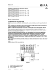
Operating instructions Radio weather station 0334 .. Notes regarding the battery Batteries and button cells do not belong in the hands of children. Contact a doctor immediately if a button cell has been swallowed. Replace empty batteries with an identical type or a type with the same values. Remove used batteries immediately and dispose of them in an environmentally-friendly way. Table of contents Commissioning and installation Commissioning the radio sensor ...............................................4 Commissioning the radio weather station .................................6 Replacing batteries ...................................................................8 Resetting the weather station and radio sensor ........................8 Selecting the installation site ....................................................9 Installing the radio weather station .........................................10 Removing the radio weather station .......................................11 Installing the radio sensor .......................................................12 Operating the radio weather station with the power adapter ........................................................................13 Operation Operating the radio weather station ........................................14 Weather forecast ....................................................................15 Temperature/Humidity ............................................................16 Barometer...............................................................................19 Radio controlled clock ............................................................20 Setting the time and date manually.........................................20 Display symbols......................................................................22 Technical data ....................................................................... 24 Warranty................................................................................ 26 3 Commissioning the radio sensor Front THERMO HYGRO RF CLOCK Time Reception of radio controlled clock signal Temperature/Humidity Channel number, battery level CH S E N S O R LED status display Rear (battery compartment open) Wall mounting SEARCH °C/°F RESET EU UK 12345 CH °C/°F button Temperature display unit °C or °F Channel selector switch (ch. 1 - 5) Reset button Search button EU/UK selector switch Radio controlled clock signal selection Battery compartment 2 x UM-3 (AA), 1.5 V Fold-out stand 4 On the back of the radio sensor: 1. Loosen and remove screws on battery compartment. 2. Set a radio channel (slider switch, ch. 1 - 5). Different radio channels must be set if several radio sensors are used. i SEARCH °C/°F RESET EU UK 12345 CH Outside sensor on channel 1 An outside sensor must be connected to channel 1 for the "snow" indicator in the forecast area. 3. Specify radio controlled clock signal format (slider switch EU/UK). EU= Europe, UK= Great Britain. 4. Insert batteries (2 x UM-3 (AA) 1.5 V). Note the polarity shown in the battery compartment. 5. Specify the temperature display unit (°C or °F) with the °C/°F button (applies only for the display of the radio sensor). 6. Press the Reset button until the display goes out. 7. When the display appears again, press the Search button until the antenna symbol flashes in the display. ✓ The radio sensor now searches for the radio controlled clock signal. This process may last up to 10 minutes. It is complete when the antenna symbol continuously displays the reception quality: no signal: weak signal: strong signal: If no radio controlled clock signals were received, relocate the radio sensor and press the Search button again. If a radio controlled clock signal is still not received, set clock manually (see Page 20). 8. Close battery compartment and screw in screws. 5 Commissioning the radio weather station Back (without mounting plate) Plug contact for power adapter Power supply (9 V) via a 230 V power adapter Polarity of the power adapter Battery compartment 2 x CR2032, 3 V Reset °C/°F mb/hPA / inHG mb/hPa / inHg switch Unit of air pressure display in mb/hPa or inHg °C/°F switch Temperature display unit °C or °F Reset button 6 On the back of the radio weather station: 1. Insert button cells (2 x CR 2032 3 V) or connect the optional power adapter (see Page 13). Note the polarity shown. 2. Select the temperature unit with the °C/°F button. 3. Specify the unit for the air pressure display with the mb/hPa / inHg button. mb/hPa = millibar/hectopascal inHg = inches of mercury column 4. Push the Reset button with a pointed object. ✓ The radio weather station searches for radio sensors. The search is ended automatically after 5 minutes. If during the search a channel in the temperature/humidity range is switched to, the search is indicated by the flashing of the following symbols: 5. Set time and date format if necessary (see Page 21) 6. Adjust inside temperature display if necessary (see Page 18). i Searching for radio sensors The search for radio sensors can be restarted (e.g. after changing the batteries), by switching to the temperature/ humidity area with Mode and then pressing and holding Memo and Ch for 2 seconds. i Assigning several radio weather stations to a radio sensor Up to five radio weather stations can be assigned to a radio sensor. For this, the Reset button must be pressed at each radio weather station during commissioning. 7 Replacing batteries Battery replacement indicator The weather station features two battery replacement indicators. The indicator in the weather forecast area indicates the battery level in the radio weather station. The battery indicator in the temperature/humidity area indicates the level of the batteries in the selected radio sensor. %RH COM If is shown on the radio sensor or on the weather station, new batteries must be inserted as shown starting on Page 4 for commissioning. After inserting the new batteries, press the Reset button. For the radio sensor, press the Search button as well. Resetting the weather station and radio sensor The Reset button is located on the back of the weather station or in the battery compartment of the radio sensor. Press Reset each time the batteries are changed or when the device responds unexpectedly (e.g. if the radio connection with the radio sensor cannot be established). Attention By pressing Reset, all settings at the weather station are returned to the default values, and all saved information (e.g. min. and max. values) is lost. 8 Selecting the installation site i Testing signal transmission Before final installation, ensure that the positioning of the radio sensor(s) and radio weather station enable proper signal transmission. Conditions for optimum operation: • For optimum readability, the radio weather station should be installed at eye level (approx. 1.7 m). • The radio sensor should be mounted firedamp outside. Direct sunlight, rain or snow can interfere with proper measurement by the outside sensor. • Set up radio sensor within a radius of max. 100 metres (free field) from the radio weather station. The specified range is the free field range, i.e. the range for visual contact between the radio sensor and radio weather station. In practical situations, however, there are walls, ceilings etc. between the transmitter and receiver, which reduce the range accordingly. • Set up radio sensor at a sufficient distance from metallic objects or electronic equipment. • Cold (e.g. operation in the winter) has a negative effect on battery voltage. This could lead to decreased range. • The radio transmission from the radio sensor to the radio weather station occurs in the 433 MHz range, which is also used by other devices. This can lead to restricted operation and range. 9 Installing the radio weather station The radio weather station can be installed with or without a cover frame. If installed on a flush-mounted box (when used with power adapter), the weather station must be installed with a cover frame. Cover frames Wall mounting attachment Mounting plate Box mounting attachment %RH Hr hPa mb Weather station Mode Set Memo Ch Installation with a cover frame is described in the following. For installation without cover frames, proceed in the same manner: Wall mounting 1. Determine the installation site and mark mounting holes. 2. Drill mounting holes and insert plugs. 3. Attach mounting plate with the cover frame to the wall with two screws. 4. Attach weather station to the mounting plate and snap it in. Hr %RH 10 hPa mb Box mounting 1. Connect power adapter to 230 V (see Page 13). 2. Place mounting plate and cover frame on the flush-mounted box. 3. Secure mounting plate to the support ring of the flush-mounted box with two screws. 4. Connect plug terminal and attach to the contact of the radio weather station. 5. Attach weather station to the mounting plate and snap it in. Hr %RH hPa mb Removing the radio weather station To open the radio weather station: 1. Carefully push lower snap clip of the radio weather station upward with a screwdriver. Hr hPa mb Mode Set Memo Ch 2. Remove the weather station from the mounting plate at the same time. 11 Installing the radio sensor Find a suitable location for the radio sensor: Direct sunlight, rain or snow can negatively effect measurement. The radio sensor can be stood up or hung. Placing 1. Fold out stand on the back of the radio sensor and secure it there. 2. Stand up radio sensor in a suitable location. Hanging The radio sensor can be hung on a screw via the hanging eyelet on the back. 1. Screw the screw (not included) into the wall at the desired location. 2. Hang the radio sensor on the screw via the hanging eyelet on the back. 12 Operating the radio weather station with the power adapter Attention Installation and mounting of electrical devices may only be carried out by a qualified electrician. With the optional power adapter, the radio weather station can be operated with 230 V. The radio weather station must be installed on a flush-mounted box (we recommend a deep box) for this. The power adapter must be connected as follows: 1. Connect power adapter to 230 V. 2. Connect a suitable cable to the 9 V output of the power adapter. 3. Attach plug terminal to this cable. 4. Attach plug terminal to the connections on the back of the radio weather station. Note the polarity indicated below the connection on the weather station. ✓ Proper connection of the power adapter is indicated by the absence of the plug symbol in the weather forecast area. i 230 V~ L N 230 V~ Netzadapter 230 V Wetterstation 9V + + Batteries and power adapter Batteries can also be inserted into the radio weather station while the power adapter is connected. They are then used to bridge a power failure, should one occur. 13 Operating the radio weather station Front Weather forecast Animated weather forecast Battery level Power supply type (battery/power adapter) Temperature/Humidity Actual value, min./max. value, trend and comfort display, battery level of the radio sensors COM %RH Hr hPa mb CHANNEL Mode Set Memo Ch Barometer Trend display, 24 hour memory Radio controlled clock Time, calendar Moon-phase indicator Operating buttons Mode, Set, Memo, Ch Basic button functions • Mode moves the arrow ▼ for selection of the areas. "Temperature/Humidity", "Barometer", "Radio controlled clock". ▼ below the area divider is the active area • Set for changing the setting values • Memo for polling saved values • Ch for radio sensor selection 14 Weather forecast The weather station creates a weather forecast for the next 12 to 24 hours for the area within a radius of 30 - 50 km. This forecast is based on air pressure trend measurements. The forecasted weather is indicated via animated symbols toward the top. Day Night (6:00 a.m. - 6:00 p.m.) (6:00 p.m. - 6:00 a.m.) Sunny/Clear Partially cloudy Cloudy Rain Snow If a temperature of 2 °C or lower is registered at the radio sensor on channel 1, snow is indicated instead of rain. 15 Temperature/Humidity The radio weather station can show the following information for each assigned radio sensor: %RH COM • Current, minimum and maximum measured values for temperature and relative humidity (in percent). • Comfort zone (WET, COM, DRY) and trend symbols (rising, falling, steady). Displaying temperature and humidity of the radio sensors The individual radio sensors can be selected manually to have them display, for example, the outside temperature: 1. Press Mode until ▼ is found in the temperature/humidity area. 2. Choose between the inside display and the radio sensors (channels 1 through 5) with Ch. ✓ The house symbol indicates the inside display or the channel number of the selected radio sensor . Starting automatic polling of radio sensors The radio sensors can be polled automatically. The data of each radio sensor is displayed for 3 seconds. Automatic polling is started as follows: 1. Press Mode until ▼ is found in the temperature/humidity area. 2. Press and hold Ch for 5 seconds. ✓ The data of the radio sensors are displayed one after another. Ending automatic polling To end automatic polling: 1. Press Mode until ▼ is found in the temperature/humidity area. 2. Press Ch briefly. 16 Displaying minimum/maximum values The radio weather station saves the minimum and maximum temperature and humidity values. These values can be polled as follows: 1. Press Mode until ▼ is found in the temperature/humidity area. 2. Choose between the inside temperature and the desired radio sensor (channels 1 through 5) with Ch. 3. Switch between the maximum, minimum and current values with Memo. The current values are displayed again 10 seconds after the last push of the button. Deleting minimum/maximum values The min./max. values are deleted as follows: 1. Press Mode until ▼ is found in the temperature/humidity area. 2. Choose between the inside temperature and the desired radio sensor (channels 1 through 5) with Ch. 3. Switch to the maximum or minimum value with Memo. 4. Press and hold Memo for 2 seconds. ✓ The memory is cleared. The current measured values are displayed. i Note When deleting, only the saved min./max. values of the indicated channel are deleted. 17 Calibrating display of inside temperature Depending on the installation site of the radio weather station, the displayed inside temperature may deviate from the actual room temperature. The display of the inside temperature can be adjusted by +/- 10° in 1° increments: 1. Press Mode until ▼ is found in the temperature/humidity area. 2. Select the display of the inside temperature with Ch. 3. Press and hold Set until the temperature display flashes. ✓ The current measured temperature - 10° is displayed. 4. The temperature display is increased by 1° with Set. 5. Confirm the set temperature with Mode. Selecting temperature display unit The temperature can be displayed in °C or °F. 1. Select desired unit with the slider switch (°C/°F) on the back of the radio weather station. Comfort display %RH In addition to the display of the humidity in %, so-called "comfort zones" are displayed, for which the following conditions apply: COM Zone Temperature Humidity DRY any < 40% COM 20 - 25 °C (68 - 77 °F) 40 - 70% WET any > 70% 18 Barometer Hr hPa mb The weather station indicates the current air pressure and charts air pressure fluctuations to create a weather forecast. Displaying air pressure history The weather station saves the measured air pressure from the last 24 hours. These values are polled as follows: 1. Press Mode until ▼ is found in the barometer area. 2. Select the individual measured values with Memo. shows the time of the measurement here. Hr ✓ The current air pressure is displayed again approx. 10 seconds after the last push of the button. Selecting air pressure unit The air pressure can either be displayed in mb/hPa or in inHg. The unit is set with the slider switch (mb/hPa / inHg) on the back of the radio weather station. Setting altitude The altitude is used for calculation of the relative air pressure at seal level as compared to the absolute air pressure at the installation site. This relative value is an important reference value for correctly interpreting weather reports which are based on the relative air pressure, for example. The altitude of your city (which could be obtained from a topographical or trail map, for example) is set as follows: 1. Press Mode until ▼ is found in the barometer area. 2. Press and hold Mode until the current set altitude is displayed. 3. Set the altitude in increments of 10 metres with Set (-100 to 2,500 m). 4. Confirm with Mode. 19 Radio controlled clock The radio sensor automatically sets the time and date using official time signals from Mainflingen, Germany (near Frankfurt am Main) or Rugby (Great Britain). The time signals are received by the radio sensor if it is located within approx. 1,500 km from the time signal transmitter and are forwarded to the radio weather station. The initial reception can last 2 - 10 minutes and is started when the Search button on the radio sensor is pressed. The antenna symbol stops flashing when reception is complete. If automatic time synchronisation is not possible, the time can be set manually at the weather station Setting the time and date manually i Note If reception of the official time signal is not possible, the time and date can be set manually. In this case, the radio controlled clock function must first be deactivated. Deactivating the radio controlled clock function 1. Press Mode until ▼ is found in the clock area. 2. Press Mode and Set until the symbol disappears. Activating the radio controlled clock function 1. Press Mode until ▼ is found in the clock area. 2. Press Set until the 20 symbol appears. Setting time, date and language 1. Press Mode until ▼ is found in the clock area. 2. Press and hold Mode until the time zone compensation flashes. 3. Set the time zone compensation (+/- 23 hours) with Set and confirm with Mode. 4. Make the following settings in the exactly the same way. Set each one with Set and confirm with Mode: • Time format (24 hr/12 hr) • Hours and minutes • Year • Date format month/day (M D) or day/month (D M) • Month and day • Language: The selected language determines the display of the days of the week. You can choose between the languages (E) English, (D) German, (F) French, (I) Italian and (S) Spanish. Switching the time/date display The radio weather station can present the time and date in four ways: • Time with seconds • Time with day of the week • Time with time zone compensation • Calendar The display is switched as follows: 1. Press Mode until ▼ is found in the clock area. 2. Select the desired display with Set. 21 Display symbols Trend display The temperature, humidity and air pressure trends are displayed via the following symbols: rising steady falling Moon-phase indicator The weather station calculates the corresponding phase of the moon using the date: 22 waning crescent waning gibbous new moon full moon waxing crescent waning gibbous waxing crescent (first quarter) waning gibbous (last quarter) House symbols The house symbol in the temperature/humidity area provides information on the selected channel and the reception status: Weather station is searching for radio sensors. Radio sensor on channel 1 transmitting data. (The number of the radio sensor is displayed). Weather station displays the data of the inside temperature and inside humidity. Radio sensor on channel 1 not found. "--" displayed for temperature and humidity. The house symbol in the time area has the following meanings: The weather station is in contact with the radio sensor and has performed time synchronisation. The weather station is in contact with the radio sensor, but has not performed time synchronisation. The weather station is not in contact with the radio sensor, but has performed time synchronisation. The weather station is not in contact with the radio sensor and has not performed time synchronisation. The weather station cannot establish a connection with the radio sensor. 23 Technical data Weather station Dimensions (H x W x D): 126 x 55 x 19 mm Temperature Measurement range: Measurement increments: Unit: -5 °C to 50 °C (23 °F to 122 °F) 0.1 °C (0.2 °F) °C or °F Relative humidity Measurement range: Measurement increments: 25% to 95% 1% Barometer Measurement range: Unit: Altitude adjustment: 700 mb/hPa to 1050 mb/hPa (20.67 to 31.01 inHg) mb/hPa or inHg -100 to 2500 metres Channel numbers 1, 2, 3, 4 or 5 Batteries: 2 x CR 2032 3 V Radio sensor Dimensions (H x W x D): 116 x 70 x 24 mm Temperature Measurement range: Measurement increments: Unit: -20 °C to 60 °C (-4 °F to 140 °F) 0.1 °C (0.2 °F) °C or °F Relative humidity Measurement range: Measurement increments: 25% to 95% 1% Transmission frequency: 433 MHz Range: 100 metres (free field) Channel numbers: 1, 2, 3, 4 or 5 Batteries: 2 x UM-3 (AA) 1.5 V 24 i Notes on care Use a moistened, soft and clean cloth to clean the radio weather station. Avoid quick repeated wiping of the radio weather station display. This can temporarily discolour the display. This discolouration disappears automatically after a short time. 25 Warranty We provide a warranty in accordance with the statutory requirements. Please send the device postage paid with an error description to our central customer service centre. Gira Giersiepen GmbH & Co. KG Service Center Dahlienstraße 12 42477 Radevormwald, Germany The CE sign is a free trade sign addressed exclusively to the authorities and does not include any warranty of any properties. 26 27 Postfach 1220 42461 Radevormwald Germany Phone: +49(0)2195 - 602 -0 Fax: +49 (0) 21 95- 602-339 www.gira.de [email protected] 27/06 Gira Giersiepen GmbH & Co. KG Electrical Installation Systems