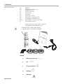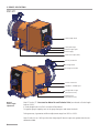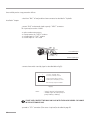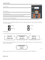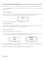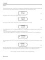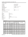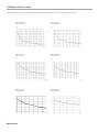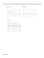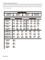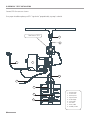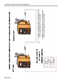
1
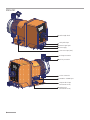
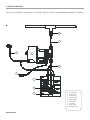
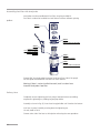
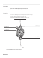
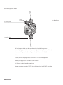
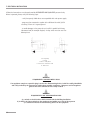
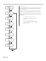
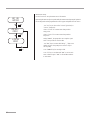
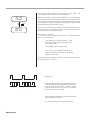
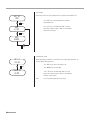
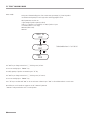
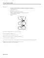
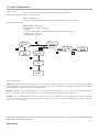
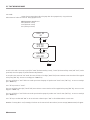
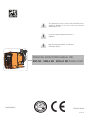
This operating instructions contains safety information that if ignored can endanger life or result in serious injury. They are indicated by this icon. 3 2 1 Use of this pump with radioactive chemicals is forbidden! D Keep the pump protected from sun and water. Avoid water splashes. C OPERATING INSTRUCTIONS MANUAL FOR KMS MF - KMSA MF - KMS AC MF DOSING PUMP B Progettato da Controllato da Approvato da Data A Data 13/05/2008 federico.renzi Edizione 3 Read Carefully ! 1 2 Foglio 1/1 1 ENGLISH Version R1-02-13 NORME CE EC RULES (STANDARD EC) NORMAS DE LA CE Direttiva Basso Voltaggio Low Voltage Directive Directiva de baja tensión ⎬ 2006/95/CE Direttiva EMC Compatibilità Elettromagnetica EMC electromagnetic compatibility directive EMC directiva de compatibilidad electromagnética ⎬ 2004/108/CE Norme armonizzate europee nell’ambito della direttiva European harmonized standards underdirective Las normas europeas armonizadas conforme a la directiva ⎬ 2006/42/CE This product is tested and certified by “WQA” to conform to NSF/ANSI-50 and NSF/ANSI-61 THIS EQUIPMENT IS FOR DRINKING WATER TREATMENT. GENERAL SAFETY GUIDELINES Danger! In emergencies the pump should be switched off immediately! Disconnect the power cable from the power supply! When using pump with aggressive chemicals observe the regulations concerning the transport and storage of aggressive fluids! When installing always observe national regulations! Manufacturer is not liable for any unauthorized use or misuse of this product that may cause injury, damage to persons or materials. Caution! Pump must be accessible at all times for both operating and servicing. Access must not be obstructed in any way! Feeder should be interlocked with a no-flow protection device. Pump and accessories must be serviced and repaired by qualified and authorized personnel only! Always discharge the liquid end before servicing the pump! Empty and rinse the liquid end before work on a pump which has been used with hazardous or unknown chemicals! Always read chemical safety datasheet! Always wear protective clothing when handling hazardous or unknown chemicals! 1. Introduction 1.1 KMS MF Series KMS MF is designed for low/middle dosing of chemicals. The pump has different working modes: Constant, Divide, Multiply, ppm, perc, mlq, batch, volt, mA. KMS MF has got: - STAND-BY input - SEFL (flow sensor) input - LEVEL input - ALARM contact output. Flow rate is determined by the stroke length and by the stroke speed. The stroke length is adjustable from 0 to 100% using the stroke length adjustment knob. However dosing accuracy is guarantee within an adjustment range from 30% to 100%. All control and setup parameters are available through a digital keyboard and they are displayed on a LCD backlit display. ✎ 1.2 KMSA MF Series Note: some functions described into this manual may need accessories not included into the pump packaging. KMSA MF is the KMS MF version with self-venting pump head. Self-venting pump head must be used when using chemicals that produce gas (i.e. hydrogen peroxide, ammonium, sodium hypoclorite at particular conditions). “Self-Venting pump head installation”. For connections ⎘ 1.3 KMS AC MF Series KMS AC MF is the KMS MF version with double supply: compressed air and power supply. Compressed air without lubrifiant and/or condensed water. Air supply pressure range must be from 6 to 10 bar. p. 5. For connections ⎘ 1.4 Working modes Pump can work in differents ways: MODE CONSTANT DIVIDE MULTIPLY External pulses from a water meter are divided by a value set during program session. The pump doses with a rate determined by this parameter. External pulses from a water meter are multiplied by a value set during program session. The pump doses with a rate determined by this parameter. PPM Dosing rate is determined by pulses from a water meter on the base of set PPM, chemical product concentration (%) and quantity for each single stroke set during program session. PERC Dosing rate is determined by pulses from a water meter on the base of set PERC (%), chemical product concentration (%) and quantity for each single stroke set during program session. MLQ Dosing rate is determined by pulses from a water meter on the base of set MLQ (milliliters per quintal), chemical product concentration (%) and quantity for each single stroke set during program session. BATCH ✎ WORKING MODES Pump doses at a constant rate set in “SPH” (strokes for hour), “SPM” (strokes for minute) or “LPH” (litres per hour) parameters set during program session. Signal from an external contact starts the pump to dose the set quantity. VOLT Voltage from an external device drives the pump that doses proportionally using a minimum and maximum of strokes for minute set during program session (0 ÷ 10 VDC). mA Current from an external device drives the pump that doses proportionally using a minimum and maximum of strokes for minute set during program session. In MULTIPLY, DIVIDE, PPM, PERC, MLQ working modes, the pump, connected to a pulse emitter water meter, shows the instant flow. 3 2. Unpacking Included into package: n.4 n.4 n.1 n.1 n.1 n.1 m 2 m 2 m 2 m 2,5 n.1 Dibbles ø6 Self tapping screws 4,5 x 40 Delayed fuse 5 X 20 Foot filter with valve Injection valve Level probe Delivery pipe * (PVDF) Suction pipe * (transparent PVC) Discharge pipe (transparent PVC) Signal cable for “Stand-by” and “Alarm” This installation manual * If hose is 6x8 there is only a 4meters long hose. Cut to obtain suction and delivery hoses. PLEASE DO NOT TRASH PACKAGING. IT CAN BE USED TO RETURN THE PUMP. Legend: a. Alternating Current; b.DC, c. Protective Earth; d.Standby; e. 4 Warning - 3. Pump’s description KMS MF Stroke length knob Level probe input External signal input Power supply Progettato da Massimo_F Controllato da Flow sensor input (SEFL) Modificato da Materiale: Data Toll. Gen. 0.05 26/05/2011 PVC GRIGIO Edizione A4emec 00 Delivery connection Foglio 1/1 Discharge knob Discharge connection Suction connection STAND-BY / ALARM input Compressed air input (mod. KMS AC MF) Venting valve (mod. KMS AC MF) Manual stroke length adjustment Modificato da Toll. Gen. Max CC/stroke ( ⎘ Construction Materials and26/05/2011 Technical info) are referred to Stroke length 0.05 Materiale: knob on 100%. PVC GRIGIO If Stroke length knob is on 50% cc/stroke will be halved. Edizione Foglio A4emec 1 00 To regulate pump’s capacity: turn on the pump then press and rotate1 /the knob. Progettato da Massimo_F Controllato da Data Dosing accuracy is guarantee within an adjustment range from 30% to 100%. Note: if knob isn’t on 100% position then the pump will dose at a pressure greater than the one declared on label. 5 KMSA MF Stroke length knob Level probe input External signal input Power supply Progettato da Massimo_F Controllato da Modificato da Flow sensor input (SEFL) Data Materiale: Toll. Gen. 0.05 26/05/2011 PVC GRIGIO Discharge connection Foglio Edizione A4emec 00 1/1 Delivery connection Suction connection STAND-BY / ALARM input Compressed air input (mod. KMSA AC MF) Venting valve (mod. KMSA AC MF) Progettato da Massimo_F Controllato da Modificato da Materiale: Data PVC GRIGIO A4emec 6 Toll. Gen. 0.05 26/05/2011 Edizione 00 Foglio 1/1 4. Before to Install warnings Pump’s installation and operativity is made in 4 main steps: Pump’s installation Hydraulic Installation (hoses, level probe, injection valve) Electrical Installation (main power connection, SEFL installation, priming) Programming the pump. Before to start, please read carefully the following safety information. Protective clothes Wear always protective clothes as masks, gloves, safety glasses, ear plugs or ear muffs and further security devices during ALL installation procedure and while handling chemicals. Installation location Pump must be installed in a safety place and fixed to the table / wall to avoid vibration problems! Pump must be installed in a easy accessible place! Pump must be installed in horizontal position! Avoid water splashes and direct sun! Hoses and Valves Suction and delivery hoses must be installed in vertical position! All hoses connections must be performed using only hands’ force! No tongs required! Delivery hose must be firmly fixed to avoid suddenly movements that could damage near objects! Suction hose must be shorter as possible and installed in vertical position to avoid air bubbles suction! Use only hoses compatibles with product to dose! See chemical compatibility table. If dosing product is not listed please consult full compatibility table or contact chemical’s manufacturer! Feeder should be interlocked with a no-flow protection device to automatically shut-off the pumps when there is no flow! Adequate measures shall be taken to prevent cross connection of chemicals! Chemical feeding must be stopped during backwash cycles and periods of noflow as these conditions may introduce the potential for chemical overdosing. Not doing so may result in elevated chemical concentrations and hazerdous gas introduction into the pool or spa. 7 5. Installation Draw Pump must be installed in a stable support (for example a table) at a maximum height (from tank’s bottom) of 1,5 meters. 4 3 8 1 2 9 5 6 7 8 1 - Dosing Pump 2 - Suction Hose 3 - Delivery Hose 4 - Injection Valve 5 - Air discharge 6 - Level Probe 7 - Foot Filter 8 - Power Cable 9 - Standby / Alarm 6. Hydraulic Installation Hydraulic connections are: Suction Hose with level probe and foot filter Delivery Hose with injection valve Discharge Hose Suction Hose. Completely unscrew tightening nut from pump’s head and remove assembling components: tightening nut, holding ring and pipe holder. Assembly as shown in fig. (A). Insert hose into pipe holder until it reaches the bottom. Lock hose on pump’s head by screwing down the tightening nut. Use only hands to do it! Connect other side of the hose to the foot filter using the same procedure. Suction Hose Tightening Nut Holding Ring Pipe Holder O-ring Valve fig. (A) 9 Assembling foot filter with level probe. Level probe must be assembled with foot filter using the provided kit. Foot valve is made to be installed into tank’s bottom without sediments priming problem. STEP 5 STEP 4 INSERT RING AS SHOWN STEP 3 INSERT PROBE WITH N.O. CONTACT UNTIL TO HEAR A CLICK STEP 2 INSERT FLOATER STEP 1 INSERT RING AS SHOWN Connect BNC from level probe into pump’s level input (front side of the pump). Put level probe assembled with foot filter into tank’s bottom. Warning: If there is a mixer installed into tank, install a suction lance instead of level probe / foot filter. Progettato da Controllato da Data Modificato da, il Massimo_F FILTRO DI ASPIRAZIONE CON SONDA DI LIVELLO - CONTATTO N.O. Materiale: Toll. Gen. `0.05 24/10/2003 FP+CE+PVDF 076.0147.1 Edizione Foglio 00 1 /1 Delivery Hose. Completely unscrew tightening nut from pump’s head and remove assembling components: tightening nut, holding ring and pipe holder. Assembly as shown in fig. (A). Insert hose into pipe holder until it reaches the bottom. Lock hose on pump’s head by screwing down the tightening nut. Use only hands to do it! Connect other side of the hose to the injection valve using the same procedure. 10 Injection Valve. Injection valve must be installed on plant from water’s input. Injection valve will open at pressure greater than 0,3bar. Dicharge hose. Insert one side of discharge hose into discharge connector as shown in fig (C). Insert other side of discharge hose into product’s tank. During priming procedure product exceeding will flow into tank. 6 5 4 3 2 D to delivery hose Discharge knob to discharge hose C to suction hose B A Progettato da Controllato da Approvato da federico.renzi 6 5 For priming procedure see the paragraph “Priming”. 11 fig (C) 4 3 2 Self-venting pump head. 6 5 4 3 2 D to bleed hose to delivery hose C to suction hose B A Progettato da 6 5 4 Hoses assembling procedure (including purge hose) is described in fig. (A). 3 Notes: - suction, delivery and purge valves are DIFFERENT! Do not exchange them! - delivery and purge hoses are made of same material! - it’s allowed to lightly bend discharge hose! - during calibration procedure (“TEST”) insert discharge hose into BECKER test-tube! 12 Controllato da Approvato da federico.renzi Self-venting pump head must be used when using chemicals that produce gas (i.e. hydrogen peroxide, ammonium, sodium hypoclorite at particular conditions). 2 7. Electrical Installation All electrical connections must be performed by AUTHORIZED AND QUALIFIED personnel only. Before to proceed, please, verify the following steps: - verify that pump’s label values are compatible with main power supply. - pump must be connected to a plant with a differential switch (0,03A sensitivity) if there isn’t a good ground. - to avoid damages to the pump do not install it in parallel with heavy inductance load (for example: engines). A relay switch must be used. See below picture. P - Dosing Pump R - Relay I - Switch or safety device E - Electrovalve or inductance load A - Main Power WARNING IF EQUIPMENT IS SUPPLIED WITH A PLUG: If an appliance coupler or separable plug is used as the disconnecting device, it shall be readily identifiable and easily reached by the operator. For single-phase portable equipment, a plug on a cord of length not greater than 3m is considered to be easily reached. WARNING IF EQUIPMENT IS NOT SUPPLIED WITH A PLUG: a) a switch or circuit-breaker shall be included in the building installation b) it shall be in close proximity to the equipment and within easy reach of the operator c) it shall be marked as the disconnetting device for the equipment 13 Once verified previous steps proceed as follows: Installation” chapter. - check that “BNC” of level probe has been connected as described in “Hydraulic - connect “BNC” and external signal to pump’s “INPUT” connectors. This input may be used as follows: - as pulse sender water meter or - as startup contact for “BATCH” mode or - as voltage input for “VOLT” mode or - as current input for “mA” mode Level Probe Input External Signal Input - connect alarm and/or stand-by signal as described below fig (D): 1 2 1: (Green) “Stand-by” Input 4: (Yellow) “Stand-by” Ground 2: (Brown) Alarm (Relay) Common 3: (White) N.O. Alarm(Relay) Contact 4 3 Max load relay output: 2A 250VAC fig (D) Notes: If not used, protect the mini DIN plug with the black rubber cap loose in the accessories bag. 14 - “Alarm” signal isn’t fuse protected - “Standby” signal has main priority on pump’s enabling / disabling. - proceed to “SEFL” connection (Flow sensor is optional) as described in page 56. 8. Basic Settings LCD backlit display Storke Lenght Knob Scroll and increase digit Turn the pump on or off and exit from setup menu (without saving parameters) Enter / exit from setup menu (saving parameters) The “KMS MF” pump is equipped with a keyboard.To avoid any misunderstanding during next chapters all keys will be described as shown on this legend: ON/OFF “UP” key“ESC” key ESC “RIGHT” key“E” key E Menu navigation: To enter into programming mode press and keep pressed “E” key from main screen (fig.3): upkeep 000m 00s STROKES 100 SPM batch waiting fig.3 Main screen (fig.3) may appear different if “PPM” or “BATCH” mode is enabled. After about 4 seconds the pump will show the password screen (fig.5): password 0000 Default password is “0000”. Just press “E” key. Otherwise insert password using “UP” and “RIGHT” keys. 15 fig.5 Saving / Discarding changes / Activating working mode Once edited data into setup menu it’s possible to save them by pressing “E” key or to discard them by pressing “ESC” key. To activate a working mode (Constant, Divide, Multiply, PPM, PERC, MLQ, Batch, Volt, mA) select the required mode and confirm it using “E” key. Turning on and off the pump “ESC” key has a double function. It can be used to discard all changes made into setup mode or to turn on/off the pump. To turn on/off the pump press and keep pressed this key while in main screen (fig.3). The pumps will show: OFF -----------------fig.6 To return into operating mode press “ESC” key. Alarm output logical working. The pump has an “Alarm” output that changes its status (from N.O. to N.C. or viceversa) when a signal is received from “LEVEL” and/or “SEFL” and/or “STAND-BY”. To set this alarm refer to related chapter. Full menu / Short Menu mode When entering into SETUP display shows access mode menu: If this is the first time into SETUP menu then the pump will automatically set itself into “FULL” menu mode as shown in fig. A. Just press “E” key to confirm. This mode will show all pump functions and working modes. SHORT MENU FULL MENU fig. A fig. B Next time the SETUP menu will be reached it will possible to operate with “SHORT” menu configuration to change only selected mode parameters as shown in fig. B. Press “E” to confirm. Note: “SHORT” menu option is not available during first time into SETUP menu or after a reset. 16 9. Priming PRIMING To proceed follow these steps: connect all hoses to the pump; open dischage valve by completely turning the discharging knob (counter clock-wise). Power up the pump and turn stroke lenght knob to 100%. After pump’s intro (fig.1): KMS MF R: 1.xx fig.1 the pump will show the “Delay” (pump’s activation delay) as shown fig.2: WAITING 00:59 fig.2 Press any key to skip the “Delay”. Pump will show “Srokes” (actual strokes) as shown in fig.3: STROKES 100 SPM fig.3 In any working mode, if a SEFL is installed and enabled (see SEFL Setup procedure), the display will show the icon (asterisk as in fig. 4): - if SEFL works correctly, the asterisk blinks to any pulses given by the solenoid; - if the asterisk does not appear, there is an anomaly (i.e.: hoses and/or valves are obstructed, SEFL in not connected, etc.). * STROKES 100 SPM fig.4 Press and keep pressed the “RIGHT” key to enter into priming mode. Pump will go for 30 seconds into priming mode as shown in fig.5. PRIMING 30 Sec. fig.5 When the chemical begins to flow out from the outgassing hose then completely close the outgassing knob (except for selfventing pump heads). This ends the priming procedure. If countdown for priming is not yet ended press “ESC” key. Now the pump is operative. Proceed to setup and programming. 17 10. Pump’s functions summary Pump’s functions summary During pump’s working mode is it possible to see furthers working information. Press more times the “UP” key to cycle through following information: STROKES 100 SPM key key Working Mode divide 000.10 MODE divide key Power Supply Voltage SUPPLY 220 VAC key key Liters/Hour or Gallons/ Hour Dosage cc/st 0.20 DOSING 0.000 lph key External signal value (in Volt and mA working mode) or actual system flow (Multiply, Divide and PPM working mode). This item is not present in Constant working mode. 18 input 196 lph key 10. Pump’s functions summary- ALARMS If any alarm is active, in the menù “Pump’s functions summary” a general alarm display will show the number of alarm active at the moment. Enter into this menu with “RIGHT” key. The windows displayed show which alarms are active. Key ALARM LEVEL ALARM N° 01 Level alarm: the level probe signals the product end. Key Key ALARM SEFL STROKES 100 SPM SEFL alarm signals an anomaly for the SEFL. Key Key ALARM STD-By MODE divide Stand-by alarm signals the pump stop. Key Over flow alarm (when using “Divide”, “Multiply”, “ppm” working mode): signals the working frequency of the pump is higher than the values on the label. over flow Key Key SUPPLY 220 VAC Power alarm signals the power supply is out of range (from 180 to 260 VAC). ALARM POWER Key Key Stroke alarm signals that it has been set a capacity higher than the value on the label. ALARM stroke DOSING 0.000 lph Key Key input 196 lph Key Key 19 ALARM batch Batch alarm signals that the pumps has received a pulse while in Batch working mode. This diagram shows all the possible alarms. 11. Quick Guide - Main Menu (Prog [1] Mode) PROG [1] MODE Mode [1] CONSTANT Key E E Key Key Mode [2] DIVIDE E Key See page 35 Mode [3] MULTIPLY E Key Key Key PROG [2] SETUP See page 19 See page 36 Key Key E Mode [4] PPM E Key See page 37 Mode [5] PERC E Key Key Key See page 38 Key PROG [3] STAT Key See page 20 Mode [&] MLQ E Key See page 39 Mode [7] BATCH E Key Key E See page 40 Key Mode [8] VOLT E Key See page 41 Mode [9] mA E Key See page 42 Key Key 20 Key See page 34 12. Quick Guide - Main Menu (Prog [2] Setup) SET [01] CC/ST E key See pag. 22 E key See pag. 22 E key key PROG [1] MODE See pag. 19 Key Set [02] test E key set [03] level Key See pag. 23 key set [04] Sefl E set [05] Stand-by E key See pag. 24 E key See pag. 24 E key See pag. 25 E key key PROG [2] SETUP set [06] out al Key key E set [07] alarms Key Key key set [08] wmeter See pag. 25 key set [09] timeout E key See pag. 26 E key key set [10] unit See pag. 27 key PROG [3] STAT See pag. 21 Key set [11) delay set [12) password key 21 E key See pag. 27 E key See pag. 28 key E key See pag. 24 key 13. Quick Guide - Main Menu (Prog [3] Stat) PROG [1] MODE See pag. 18 Key Key PROG [2] SETUP E See pag. 19 Key E Key Key PROG [3] STAT ->TOt dos counter See pag. 38 Key E 22 15. Setup Pump’s initial setup Apart of choosen working mode, the pump must be prepared to operate by setting the main parameters into “SETUP” menu. To enter into this menu please follow the “Quick Guide through menu” at page 20. CC per Stroke. SET [01] CC/ST Enter here the cc/stroke value obtained during “Test” mode (calibration). Key E Use “UP” key to increase of one unit the blinking digit “_”. Press “RIGHT” key to skip on next digit. Press “E” key to save data and “ESC” exit to main menu. Otherwise press “ESC” to discard data and exit to main menu. CC/ST 10.00 Calibration. This procedure defines the cc quantity (cubical centimeters) that the pump feed every single injection. To determine this value the pump must be calibrated. SET [02] TEST E TEST OFF ST 020 Key 1) Install the pump on plant and insert the suction hose (with its level probe / foot filter) into a BEKER “test-tube”. If pump’s model is self-priming put the discharge hose into the “test-tube“ too. 2) Power up the pump and turn the flow’s knob to required position. 3) Fill up the “test-tube” with the chemical until to reach a known value. 4) From setup menu choose “TEST”, and insert 20”. This value is the strokes that the pump will produce during the procedure. 6) Press “E”. The pump will begin to produce the 20 strokes and to suck the chemical from the “test-tube”. TEST ON ST 020 7) At the end of 20 strokes the pump will stop. Read the value of chemical left into “test-tube”. 8) Substract the initial value to the left value. 9) Divide the result with the ST value (20). 10) Type this value into “CC/ST” (Set [01]) as previously described. 11) If obtained result is too small or too big, please, try to change strokes value (20). 23 Pre Level Alarm (Reserve). SET [03] LEVEL E This function defines a pre-alarm status to inform user that the dosing product is near to end. Reserve value to be set, must be calculated on product quantity left between foot filter and pump’s suction level. Key - Use “UP” key to increase the blinking “_” digit. -Press “RIGHT” key to skip on next digit. -Press “E” key to save data and “ESC” exit to main menu. Otherwise press “ESC” to discard data and exit to main menu. stop LIT 10.000 During the alarm the pump continues to dose but it’ll show the following picture: ALARM N° 1 Key Foot filter with level probe ALARM LEVEL Key Customizable Reserver (liters / gallons) Flow Sensor (SEFL). This function enables an external alarm and, eventually, stops the dosage if the pump does not receive a “confirmation signal” from the “SEFL”. (“SEFL” accessories is optional). SET [04] SEFL E Key -Press “RIGHT” key to skip on next digit. SEFL ENABLE -Press again “RIGHT” key to choose the working procedure. -Press “UP” key to choose if pump must be stopped after a numbers of pulses (YES) or continue to dose (NO). SEFL 20 stop yes E (fig. A) Key recovery fault yes E recovery AFTER005 24 - Use “UP” key to increase the blinking “_” digit and set the number of failing strokes before to stop or not the pump. It is possible to set a number from 1 to 99. Setting 00, the SEFL will be disabled (DIS). key - Press “E” key to setup fault recovery (recovery fault) options. Setting “YES” as selected option if the flow sensor will have unreliable strokes it will recover them while flow sensor is still working in synching with it. Set this function by choosing how many unreliable strokes will be needed to recover dosage. If entered value is lower than previous one (fig. A) then SEFL function will be disabled. While into recovering mode, if there is not synchrony with SEFL, the unreliable strokes numbers will not decrease. The maximum unreliable strokes numbers is determined by the number of failing strokes previuously set. Passing over this value an alarm (ALARM SEFL) will be generated by the pump. Press “UP” to set Recovery fault on NO. -Press “E” key to save data and “ESC” to exit to main menu. Otherwise press “ESC” to discard data and exit to main menu. SET [05] Stand-by Key E “Stand-By” signal. This function allows the pump to dose only when an external signal is received from “Stand-by” input. This signal can be enabled as a N.O. contact (Normally Opened) , N.C. contact (Normally Closed) or disabled. STand-by disabled Key STand-by NC Key STand-by NO - Use “UP” key to change working mode for “Stand by” signal. -Press “E” key to save data and “ESC” to exit to main menu. Otherwise press “ESC” to discard data and exit to main menu. Key “Out Alarm” signal. SET [06] out al Key E out alarm n.c. Key out alarm n.o. Key 25 This function allows to manage the alarm output contact . The alarm can be set as “N.O.” contact (Normally Open) or “N.C.” contact (Normally Closed). - Use “UP” key to change working mode for “Out Al” signal. -Press “E” key to save data and exit to main menu. Otherwise press “ESC” to discard data and exit to main menu. Alarms Management. SET [07] aLARMS E Use this function to enable/disable the relay output for level alarm (lev) and/or standby (stby) and/or flow sensor (sefl) and/or ppm and/or percentage (PERC) and/or MLQ and/or Batch. Key If alarm is activated for one or more events then the output relay will be enabled, the pump will show the alarm status and it’ll stop or not the dosing activity. ALARM[1] LEV EN If alarm is not activated for one or more events then the output relay will be disabled, the pump will show the alarm status and it’ll stop or not the dosing activity. Key ALARM[2] stby EN -Use “RIGHT” key to enable (EN) or disable (DI) the alarm. Key -Press “E” key to save data and “ESC” to exit to main menu. Otherwise press “ESC” to discard data and exit to main menu. alarm[3] sefl en Key alarm[4] ppm en Key alarm[5] PERC Key alarm[6] MLQ Key alarm[7] BATCH Key 26 - Use “UP” key to choose the alarm to set. Water Meter Setup. Use this function to setup the water meter information. SET [08] wmeter E By entering the amount of pulses produced by the water meter the pump will optimize the working mode when programmed to work in ppm and update the stats menu. Key pulse/l 004.0 Key - Use “UP” key to choose from “Pulse/L” (pulse/liter) or “L/Pulse” (liter/pulse). Choose “L/Pulse” for a water meter that produces few pulses. Choose “Pulse/L” for a water meter that produces many pulses. Setting “000.0”, the pump does not accept the signal and it is not possible to save the data. - Use “UP” key to increase the blinking “_” digit. Enter number of pulses that pump must receive to stop or not the pump. l/pulse 004.0 Key -Press “RIGHT” key for next digit / field. -Press “E” key to save data and “ESC” to exit to main menu. Otherwise press “ESC” to discard data and exit to main menu. 27 Pulses Timeout (only for “Multiply” working mode and “PPM”, “PERC” and “MLQ” working mode when the result is a multiplication). SET [09] timeout E timeout 020 sec Key When the pump receives a pulse from the water meter it starts the dosing activity through an amount of time (from the first pulse to the following one). At the beginning the pump doesn’t know the time lapse between the first and the second pulse. So it’ll dose the product in the fastest way. From the second pulse, the pump will dose the product correctly. This function set the maximum time between a pulse and the following one. Once that this time is exceeded the pump will reinitialize the dosing activity as the first time that a pulse has been received. Default value is 120 seconds. To set “Timeout” function, between the minimum (1 sec.) and the maximum (999 sec.), proceed as follow: - Use “UP” key to increase the blinking “_” digit. Enter number of pulses that pump must receive to stop or not the pump. -Press “RIGHT” key for next digit / field. -Press “E” key to save data and “ESC” to exit to main menu. Otherwise press “ESC” to discard data and exit to main menu. Pulses Timeout does not take part in “Divide” working mode and in all working modes when the result is a division. External Pulses The first time that the pump receives a pulse it doesn’t know the the time between this pulse and the following one. So the pump will run faster as possible. “Timeout” function forces the pump to work in this way, once a specified amount of time has been exceeded. After second pulse the pump will know the time between a pulse and the following one. So it’ll dose optimizing the dosage through the time. 28 Unit Change. This function allows to choose between liters or gallons measurement unit. SET [10] unit E Key -Use “UP” key to switch between liter or gallons measurement unit. -Press “E” key to save data and “ESC” to exit to main menu. Otherwise press “ESC” to discard data and exit to main menu. UNIT litre Key unit usgal Key Startup Delay Setup. When the pump is powered is it possible to have a delay time (from 0 to 10 minutes) before dosing activities. SET [11] delay -Use “UP” key to choose the alarm to set. E power on 01 min Key -Use “RIGHT” key for next digit. -Press “E” key to save data and “ESC” to exit to main menu. Otherwise press “ESC” to discard data and exit to main menu. Note: 29 Press any key during delay time to skip it. Password Setup. “Setup” menu is password protected. Default value to enter into “setup” menu is “0000” (only numeric units). To change this password proceed as follows: SET [12] password E password 0000 Key - Use “UP” key to change first digit. -Press “RIGHT” key to move cursor over next digit. -Press “E” key to save data and “ESC” to exit to main menu. Otherwise press “ESC” to discard data and exit to main menu. Note: For lost password, please, follow the “Load default” procedure. 30 16. “Load default” and “Reset Password” procedure “LOAD DEFAULT” procedure This procedure deletes all programming data set. It reloads the default data of the pump. Follow this instructions: - unplug power supply; - pressing both “UP” and “RIGHT” keys, plug in power supply. For few seconds, the display shows LOAD DEFAULT before start up the pump. “RESET PASSWORD” procedure This procedure resets the password set and reloads the default password of the pump (“0000”). Follow this instructions: - unplug power supply; - pressing both “UP” and “ESC” keys, plug in power supply. For few seconds, the display shows RESET PASSWORD before start up the pump. 31 17. Working procedure setup Introduction. “MF” pump can work in different modes. CONSTANT mode. Pump doses at a constant rate set in “SPH” (strokes for hour), “SPM” (strokes for minute) or “LPH” (litres per hour) parameters set during program session. When to use this mode ? This mode is useful when there isn’t an input signal to control the dosing activity. Pump doses requested product quantity in constantly. Which parameters must be set ? SPH (strokes per hour), SPM (strokes per minute) LPH (litres per hour) DIVIDE mode. External pulses from a water meter are divided by a value set during program session. The pump doses with a rate determined by this parameter. When to use this mode ? This mode is useful using an external signal from a pulse sender water meter that produces elevated quantities of pulses. Pump divides these pulses to allow a correct dosing activity. Which parameters must be set ? DIVIDE (division factor) MULTIPLY mode. External pulses are multiplied by a value set during program session. The pump doses with a rate determined by this parameter. When to use this mode ? This mode is useful using an external signal from a pulse sender water meter that produces low quantities of pulses. Pump multiplies these pulses to allow a correct dosing activity. Which parameters must be set ? MULTIPLY (multiply factor) TIMEOUT PPM mode. Dosing rate is determined by pulses from a water meter, desired concentration in PPM, chemical product concentration (%) and quantity for each single stroke set during program session. When to use this mode ? This mode is useful using an external signal from a pulse sender water meter and it’s necessary to specify only PPM (parts per million) and product concentration, leaving the pump to manage coming pulses. Which parameters must be set ? PPM (parts per million product quantity) CONC (% of product’s concentration) Water Meter Pulses CC/Stroke TIMEOUT 32 PERC mode. Dosing rate is determined by pulses from a water meter, percentage (%), chemical product concentration and quantity for each single stroke set during program session. When to use this mode ? This mode is useful using an external signal from a pulse sender water meter and it’s neces- -sary to specify only % , leaving the pump to manage coming pulses. Which parameters must be set ? % (percentual product to dose) CONC (percentual of product concentration) Water Meter Pulses CC/STROKE TIMEOUT Product quantity to dose: (percentual product to dose * pump capacity l/h) Percentual of product concentration Water meter: Use a water meter to reach its maximum pulsating capabilities. Note: maximum frequency for this pump is 1Khz (1000 pulses per second). 33 MLQ mode. during program session. Dosing rate is determined by pulses from a water meter on the base of set MLQ (mil liliters per quintal), chemical product concentration (%) and quantity for each single stroke set When to use this mode ? This mode is useful when with an external signal from a pulse sender (as a water meter), it is necessary to dose the product quantity set specifing the MLQ (milliliters per quintal) and leaving the pump to manage the coming pulses. Which parameters must be set ? MLQ (product quantity in milliliters per quintal) CONC (% of product’s concentration): set 100% if product is pure Water Meter Pulses CC/Stroke TIMEOUT BATCH mode. Signal from an external contact starts the pump to dose product or to produce an amount of strokes set during program session. When to use this mode ? This function allows to begin dosing activities when pump receives an external signal. Which parameters must be set ? ST (strokes) CC (product’s quantity to dose) VOLT mode. Voltage from an external device drives the pump that doses proportionally using a minimum and maximum of strokes for minute set during program session. When to use this mode ? This mode is used with controllers provided of a proportional output in voltage. Which parameters must be set ? HIV (maximum tension) LOV (minimum tension) SPM (strokes per minute) mA mode. Current from an external device drives the pump that doses proportionally using a minimum and maximum of strokes for minute set during program session. When to use this mode ? This mode is used with controllers provided of a proportional output in current. Which parameters must be set ? HImA (maximum current) LOmA (minimum current) SPM (strokes per minute) 34 18. “CONSTANT” working mode CONSTANT mode. Pump doses at a constant rate set in“SPH” (strokes for hour), “SPM” (strokes for minute), “LPH” (litres per hour) parameters set during program session. Which parameters must be set ? SPH (strokes per hour), SPM (strokes per minute), LPH (litres per hour). mode [01] CONSTANT Key E CONSTANT 100 spm Key CONSTANT 01 sph Key CONSTANT 110.0 lph Key CONSTANT 11.00 lph Key CONSTANT 1.100 lph Key Choose “CONSTANT” working mode: “SPH” (strokes per hour), “SPM” (strokes per minute), “LPH” (litres per hour). Use “UP” key to choose between these two modes. Use “RIGHT” key to change value. For next digit press again “RIGHT” key. “LPH” value accuracy depends on cc/st value set into the Setup menu (SET [01] CC/ST). LPH max value depends on the max frequency of the pump (refer to the pump’s label). If an higher value is set, the pump will show an alarm message (ALARM STROKE). Press “E” key to save data and “ESC” to exit to main menu. Otherwise press “ESC” to discard data and exit to main menu. Note: last mode displayed before press the “E” key will be the active one. 35 19. “DIVIDE” working mode DIVIDE mode. External pulses are divided by a value set during program session. The pump doses with a frequency determined by this parameter. Which parameters must be set ? DIVIDE (divisor factor) mode [02] divide E Key DIVIDE 150.00 Use this mode if connected pulse sender water meter produces many pulses and pump must divide them for correct dosing activities. See formula below to verify this value. Minimum value accepted is 001.00. Setting a lower value the pump does not save the data. Use “UP” key to modify the value. Press “RIGHT” key to move on next digit. Press “E” key to save data and “ESC” to exit to main menu. Otherwise press “ESC” to discard data and exit to main menu. Use the following formula to find the divider to keep desired concentration. [imp/l] x [cc] ( ——————————— ) x 1000 = N [ppm] x [K] N - divisor value to enter into the pump [imp/l]- pulses/liter from pulse sender water meter [cc] - single injection quantity of dosing pump [ppm] - part per millions product quantity to dose (gr/m3) [K] - product dilution coefficient. If obtained “N” is < 1 then install a pulse sender water meter that produces more pulses. Otherwise use the “MULTIPLY” mode and multiply for 1/N. It’s also possible to fix the problem trying to decrease product dilution. 36 20. “MULTIPLY” working mode MULTIPLY mode. External pulses are multiplied by a value set during program session. The pump doses with a frequency determined by this parameter. Which parameters must be set ? MULTIPLY (multiply factor) TIMEOUT mode [03] multiply E Key multiply 010.00 Use this mode if: connected pulse sender water meter produces few pulses and pump must multiply them for correct dosing activities. See formula below to verify this value. Minimum value accepted is 001.00. Setting a lower value the pump does not save the data. Use “UP” key to modify the value. Press “RIGHT” key to move on next digit. Press “E” key to save data and “ESC” to exit to main menu. Otherwise press “ESC” to discard data and exit to main menu. Use the following formula to find the divider to keep desired concentration. [ppm] x [K] ( ————————————— ) = N ([imp/l] x [cc]) x 1000 N - multiplier value to enter into the pump [imp/l]- pulses/liter from pulse sender water meter [cc] - single injection product quantity of dosing pump [ppm] - part per millions product quantity to dose (gr/m3) [K] - product dilution coefficient. If obtained “N” is < 1 then install a pulse sender water meter that produces less pulses. Otherwise use the “DIVIDE” mode and divice for 1/N. It’s also possible to fix the problem trying to decrease product dilution. Note: before to use this mode please set the “TIMEOUT” parameter as described at page 26. 37 21. “PPM” working mode PPM mode. Dosing rate is determined by pulses from a water meter, PPM, chemical product (%) concentration and quantity for each single stroke set during program session. Which parameters must be set ? PPM (parts per million product quantity) CONC (% of product’s concentration) TIMEOUT WMETER (pulse sender water meter) CC/ST (see related page) mode [04] PPM E Key E Key ppm 0003.00 conc % 010.0 E Key UpKEEP YES TIMEOUT 00001’ E Key E Key IMP/H 100’ Use “UP” key to change selected unit (“_” blinking cursor) of PPM. To move on next digit press “RIGHT” key. To modify quantity of product concentration press “E” key. Use “UP” key to change selected unit (“_” blinking cursor) of CONC%. To move on next digit press “RIGHT” key. Press “E” key to save data and “ESC” to exit to main menu. Otherwise press “ESC” to discard data and exit to main menu. To change “TIMEOUT” option, pump activation without external pulses for a set time, choose “YES” from “UPKEEP” menu. Then set pulses/ hour to dose at the end of set time. Note: before to use this mode we suggest to set the “TIMEOUT” parameter. “TIMEOUT” take part when the result is a multiplication. 38 22. “PERC” working mode PERC mode. Dosing rate is determined by pulses from a water meter, percentage (%), chemical product concentration and quantity for each single stroke set during program session. Which parameters must be set ? % (percentage of product quantity to dose) CONC (% of product’s concentration): set 100% if product is pure CC/STROKE (refer to CC/ST setup) WMETER (water meter) TIMEOUT mode [05] PERC E key perc 03.0 Selectionable from 0.1 to 100.0% E key conc % 010.0 Use “UP” key to change selected unit (“_” blinking cursor) of PPM. To move on next digit press “RIGHT” key. To modify quantity of product concentration press “E” key. Use “UP” key to change selected unit (“_” blinking cursor) of CONC%. To move on next digit press “RIGHT” key. Press “E” key to save data and “ESC” to exit to main menu. Otherwise press “ESC” to discard data and exit to main menu. Note: before to use this mode we suggest to set the “TIMEOUT” parameter. “TIMEOUT” take part when the result is a multiplication. 39 23. “MLQ” working mode MLQ mode. Dosing rate is determined by pulses from a water meter on the base of set MLQ (milli liters per quintal), chemical product concentration (%) and quantity for each single stroke set during program session. Which parameters must be set ? MLQ (product quantity in milliliters per quintal) CONC (% of product’s concentration): set 100% if product is pure CC/STROKE (refer to CC/ST setup) WMETER (water meter) TIMEOUT mode [06] MLQ E key E key MLQ 03.00 conc % 010.0 Use “UP” key to change selected unit (“_” blinking cursor) of MLQ. To move on next digit press “RIGHT” key. To modify quantity of product concentration press “E” key. Use “UP” key to change selected unit (“_” blinking cursor) of CONC%. To move on next digit press “RIGHT” key. Press “E” key to save data and “ESC” to exit to main menu. Otherwise press “ESC” to discard data and exit to main menu. Note: before to use this mode we suggest to set the “TIMEOUT” parameter. “TIMEOUT” take part when the result is a multiplication. 40 24. “BATCH” working mode BATCH mode. Signal from an external contact starts the pump to dose the needed quantity set during program session or for the set number of strokes. When to use this mode ? This function allows to begin dosing activities when pump receives an external signal or to dose in WORK-PAUSE mode. Which parameters must be set ? MODE (EXTERNAL - MANUAL - INTERNAL) ST (strokes) CC (product’s quantity to dose only if programmed to feed a set amount of chemical) CC/STROKE (see “setup CC/ST”) CONTACT (OPEN or CLOSED) E QUANTITY ST: 00000 E Key Key E CONTACT: OPEN Key QUANTITY ST: 00000 E mode [07] EXTERNAL MANUAL INT: 000’ QUANTITY ST: 00000 E Key CONTACT: CLOSED E Key Key CONTACT: DIS. E Key ST: 1000 MANUAL Choose working mode: EXTERNAL: Pump doses within an amount of time if an external signal is received. External contact can be set as OPEN (normally open) or CLOSED. (normally closed). Press “E” from main mode, choose to dose in ST or CC using “UP” key. Set quantity dose and press “E” to continue. Define contact type using “UP” key. Press “E” to end procedure. MANUAL: Pomp doses at the end of procedure. Press “E” from main mode, choose to dose in ST or CC using “UP” key. Set quantity to dose. Press “E” to continue, review contact status and press “E”. Pump will begin to dose immediately showing quantity left. INTERNAL: This is a “WORK-PAUSE” mode. Dosing will start for set CC or ST quantity and will stop for set time. Press “E” from main mode, choose to dose in ST or CC using “UP” key. Set quantity dose and press “E” to continue. Define contact type (OPEN or CLOSED) using “UP” key. Press “E” to end procedure. NOTE: Pump must be calibrated (“TEST” function) in order to work properly into this mode. It’s not possible to program the pump for both modes. Last entry overwrite previous ones. 41 25. “VOLT” working mode VOLT mode. Voltage from an external device drives the pump that doses proportionally using a minimum and maximum of strokes for minute set during program session. Which parameters must be set ? HIV (maximum tension) LOV (minimum tension) SPM (strokes per minute) mode [08] volt E Key E Key hiv 10.0 spm: 100 lov 00.0 spm: 000 ESC Key To work in this mode is necessary to specify the “HIV” (maximum working tension), “LOV” (minimum working tension) and “SPM” (strokes per minute) values that pump will produce between the parameters. To setup this values enter into “VOLT” mode. The cursor will blink on first digit (“HIV” field). Insert maximum tension value that will be supplied to the pump (“UP” key). To move on next digit press “RIGHT” key. The cursor will blink on “SPM” field. Insert strokes per minute that pump will produce near “HIV” value (“UP” key). To move on next digit press “RIGHT” key. Press “E” key to move on “LOV”. The cursor will blink on first digit (“LOV” field). Insert minimum tension value that will be supplied to the pump (“UP” key). To move on next digit press “RIGHT” key. The cursor will blink on “SPM” field. Insert strokes per minute that pump will produce near “LOV” value (“UP” key). To move on next digit press “RIGHT” key. Press “E” key to save data and “ESC” to exit to main menu. Otherwise press “ESC” to discard data and exit to main menu. Attention: if a wrong data is set (for example, it has been set the same value for HIV and LOV) an error message (WRONG ENTRY) will appear. 42 26. “mA” working mode mA mode. Current from an external device drives the pump that doses proportionally using a minimum and maximum of strokes for minute set during program session. Which parameters must be set ? HImA (maximum current) LOmA (minimum current) SPM (strokes per minute) mode [09] ma E Key E Key hima 10.0 spm: 100 loma 00.0 spm: 000 ESC Key To work in this mode is necessary to specify the “HImA” (maximum working current), “LOmA” (minimum working current) and “SPM” (strokes per minute) values that pump will produce between the parameters. To setup this values enter into “mA” mode. The cursor will blink on first digit (“HImA” field). Insert maximum current value that will be supplied to the pump (“UP” key). To move on next digit press “RIGHT” key. The cursor will blink on “SPM” field. Insert strokes per minute that pump will produce near “HImA” value (“UP” key). To move on next digit press “RIGHT” key. Press “E” key to move on “LOmA”. The cursor will blink on first digit (“LOmA” field). Insert minimum current value that will be supplied to the pump (“UP” key). To move on next digit press “RIGHT” key. The cursor will blink on “SPM” field. Insert strokes per minute that pump will produce near “LOmA” value (“UP” key). To move on next digit press “RIGHT” key. Press “E” key to save data and “ESC” to exit to main menu. Otherwise press “ESC” to discard data and exit to main menu. Attention: if a wrong data is set (for example, it has been set the same value for HIV and LOV) an error message (WRONG ENTRY) will appear. 43 27. STATISTICS management Stat. To see dosing statistics choose “STAT” from main menu. See quick guide at pag. 21 prog [3] stat E Key -> tot dos counter E Key litres 10 Key E E Key Key reset no ESC Key Key reset yes tot dos -> counter E Key E Key pulse 5 reset no 44 reset yes “TOT DOS” means total dosed product since pump last reset. “COUNTER” means strokes numbers since pump last reset. Key 28. Troubleshooting Problem Possible Cause Pump isn’t powered. Connect it to main supply. Pump doesn’t turn on. Pump’s protection fuse is broken. Replace it. See page 45 for replacement procedure. Pump’s main board is broken. Replace it. See page 45 for replacement procedure. The foot filter is obstructed. Clean it. Pump is not dosing and solenoid is operating. Suction hose is empty. Pump must be primed. Repeat priming procedure. Air bubbles inside hydraulic circuit. Check valves - hoses - fittings. Product to dose is generating gas. Turn discharge knob and let air flow away. Use a self-venting pump head. Pump is not dosing and solenoid isn’t operating or slightly operating. Crystals presence inside valves. Check them and try to dose 2-3 liters of normal water. Change valves. Injection valve obstructed. Change it. Pump’s display shows “ERROR MEM” o “ERROR DATA” 45 ERROR MEM: error in data storage. it is necessary to reload pump’s default data, as described in “Load default procedure” on page 28. ERROR DATA: error in data setting. Check the values set. If they are correct, but the message still appears, the pump is underdimensioned. 29. Fuse and main board replacement Fuse or main board replacement is allowed to qualified personnel only. Before to operate disconnect the pump from main power and all hydraulic connections. For fuse replacement is necessary to use a 3x16 and 3x15 screwdriver and a new fuse (same model of old one). For main board replacement is necessary to use a 3x16 and 3x15 screwdriver and a new main board (same model of old one). Fuse replacement procedure: - Turn pump’s injection knob on 0%. - Remove 6 screws from pump’s back. - Pull pump’s back cover until it’s completed separated from pump’s front. Be careful of the knob’s spring. - Locate the blown fuse and replace it. - Reassemble the pump. Be careful to put back the knob’s spring. - Reinsert screws. Main board replacement procedure: - Turn pump’s injection knob on 0%. - Remove 6 screws from pump’s back. - Pull pump’s back cover until it’s completed separated from pump’s front. Be careful of the knob’s spring. - Remove board’s screws. - Completely disconnect wires from main board and replace it. Reinsert screws. - Reconnect wires to the main board (see enclosed picture). - Reassemble the pump. Be careful to put back the knob’s spring. - Reinsert screws. 46 30. Main Board TRANSFORMER FUSE L N Power Supply Solenoid GROUND + Level N.C. Relay C. N.O. Signal Input + SEFL - + Stand-by 47 A Appendix. Maintenance. Attention To ensure safety requirements of drinking water treated and the maintenance of the imrpovements as declared by the manufacturer, pump must be checked once for month. Wear needed safety devices and check hoses and all hydraulic components for: - product leak - broken hoses - corroded connections All maintenance operations must be performed by authorized and trained personnel only. If pump needs factory assistance please use original package to return it. Before to do it, please, remove all dosing product inside the pump and hoses. Use only original spare parts! 48 B Appendix. Construction Materials and Technical info TECHNICAL FEATURES Power supply: Power supply: Power supply: Power supply: 230 VAC (190-265 VAC) 115 VAC (90-135 VAC) 24 VAC (20-32 VAC) 12 VDC (10-16 VDC) Pump Strokes: Suction Height: Environment Temperature: Chemical Temperature: Installation Class: Pollution Level: Audible Noise: Packaging and Transporting Temperature: Protection degree: 0 ÷ 180 (0 ÷ 140 for KMS AC MF) 1,5 metres 0 ÷ 45°C (32 ÷ 113°F) 0 ÷ 50°C (32 ÷ 122°F) II 2 74dbA -10 ÷ 50°C (14 ÷ 122°F) IP 65 MANUFACTURING MATERIALS Case: Pump head: Diaphragm: Balls: Suction Pipe Delivery Pipe: Valve Body: O-ring: Injection connector Level Probe: Level probe cable: Foot Filter: PP PVDF, Acrilic, SS * PTFE CERAMIC, PTFE, SS * PVC PVDF PVDF, PE, SS * FP, EP, PTFE * PVDF (ceramic, HASTELLOY C276 spring) PVDF PE PVDF *as ordered. INFORMATION Flow Min cc/h Max l/h cc per stroke Min GPH Max GPH Min Max max pressure 2001 0.03 1 0.000008 0.26 0.03 0.09 20 bar 290 PSI 1802 0.06 2 0.000016 0.53 0.06 0.19 18 bar 261 PSI 1504 0.11 4 0.000029 1.06 0.11 0.37 15 bar 217 PSI 1005 0.14 5 0.000037 1.32 0.14 0.46 10 bar 145 PSI 0808 0.22 8 0.000058 2.11 0.22 0.74 8 bar 116 PSI 0510 0.28 10 0.000074 2.64 0.28 0.93 5 bar 72 PSI 0218 0.50 18 0.00013 4.76 0.50 1.67 2 bar 29 PSI INFORMATION SELF VENTING MODELS 49 200.5 0.015 0.5 4x10⁻⁶ 0.13 0.015 0.05 20 bar 290PSI 1801 0.03 1 0.000008 0.26 0.03 0.09 18 bar 261 PSI 1503 0.08 3 0.000021 0.79 0.08 0.28 15 bar 217 PSI 103,5 0.10 3.5 0.000026 0.92 0.10 0.32 10 bar 145 PSI 085,5 0.15 5,5 0.000040 1.45 0.15 0.51 8 bar 116 PSI 057,5 0.21 7.5 0.000055 1.98 0.21 0.69 5 bar 72 PSI 0213 0.37 13 0.000098 3.43 0.37 1.20 2 bar 29 PSI C Appendix. Delivery Curves Flow rate indicated is for H2O at 20°C at the rated pressure. Dosing accuracy ± 2% at constant pressure ± 0,5 bar. 2001: l/h 01 bar 20 Pump head mod. I 1802: l/h 2 bar 18 Pump head mod. L l/h l/h bar bar 1504: l/h 4 bar 15 Pump head mod. L 1005: l/h 5 bar 10 Pump head mod. L l/h l/h bar 0808: l/h 8 bar 8 Pump head mod. L 0510: l/h 10 bar 5 Pump head mod. L l/h l/h bar 50 bar bar 0501: l/h 1 bar 5 Pump head mod. I 0301: l/h 1 bar 3 Pump head mod. I 0218: l/h 18 bar 2 Pump head mod. M l/h bar 51 C Appendix. Delivery Curves for self-purge pump head 200,5: l/h 20 bar 0,5 Pump head mod. IA 1801: l/h 1 bar 18 Pump head mod. LA l/h l/h bar bar 103,5: l/h 3,5 bar 10 Pump head mod. LA 1503: l/h 3 bar 15 Pump head mod. LA l/h l/h bar bar 057,5,5: l/h 7,5 bar 5 Pump head mod. LA 085,5: l/h 5,5 bar 8 Pump head mod. LA l/h l/h bar 0213: l/h 13 bar 2 Pump head mod. MA l/h 52 bar bar C Appendix. Delivery Curves for COMPRESSED AIR MODELS 1018: l/h 18 bar 10 Pump head mod. M l/h 140 SPM bar 53 A B C D 6 138,00 [5.43] 54 6 46,65 [1.830] 5 222,20 [8,748] 5 61,00 [2,402] 4 4 Dimensions 3 3 2 91,00 [3,583] 96,28 [3,791] 2 1 1 bold : mm ( ) : inches A B C D D Appendix. Dimensions 157,60 [6.200] E Appendix. Chemical Compatibility Table Solenoid driven metering pumps are widely used to dose chemical fluids and it is important that the most suitable material in contact with fluid is selected for each application. This compatibility table serves as a useful help in this respect. All the informations in this list are verified periodically and believed to be correct on the date of issuance. All the informations in this list are based on manufacturer’s data and its own experience but since the resistance of any material depends by several factors this list is supplied only as an initial guide, in no way EMEC makes warranties of any matter respect to the informations provided in this list. Product Formula Ceram. PVDF PP PVC SS 316 PMMA Hastel. PTFE FPM EPDM NBR PE Acetic Acid, Max 75% CH3COOH 2 1 1 1 1 3 1 1 3 1 3 1 Hydrochloric Acid, Concentrate HCl 1 1 1 1 3 1 1 1 1 3 3 1 Hydrofluoric Acid 40% H2F2 3 1 3 2 3 3 2 1 1 3 3 1 Phosphoric Acid, 50% H3PO4 1 1 1 1 2 1 1 1 1 1 3 1 Nitric Acid, 65% HNO3 1 1 2 3 2 3 1 1 1 3 3 2 Sulphuric Acid, 85% H2SO4 1 1 1 1 2 3 1 1 1 3 3 1 Sulphuric Acid, 98.5% H2SO4 1 1 3 3 3 3 1 1 1 3 3 3 Amines R-NH2 1 2 1 3 1 - 1 1 3 3 1 1 Sodium Bisulphite NaHSO3 1 1 1 1 2 1 1 1 1 1 1 1 Sodium Carbonate (Soda) Na2CO3 2 1 1 1 1 1 1 1 2 1 1 1 Ferric Chloride FeCl3 1 1 1 1 3 1 1 1 1 1 1 1 Calcium Hydroxide (Slaked Lime) Ca(OH)2 1 1 1 1 1 1 1 1 1 1 1 1 Sodium Hydroxide (Caustic Soda) NaOH 2 3 1 1 1 1 1 1 2 1 2 1 Calcium Hypochlor.(Chlor.ted Lime) Ca(OCl)2 1 1 1 1 3 1 1 1 1 1 3 1 Sodium Hypochlorite, 12.5% NaOCl + NaCl 1 1 2 1 3 1 1 1 1 1 2 3 Potassium Permanganate, 10% KMnO4 1 1 1 1 1 1 1 1 1 1 3 1 Hydrogen Peroxide, 30% (Perydrol) H2O2 1 1 1 1 1 3 1 1 1 3 3 1 Aluminium Sulphate Al2(SO4)3 1 1 1 1 1 1 1 1 1 1 1 1 Copper-II-Sulphate (Roman Vitriol) CuSO4 1 1 1 1 1 1 1 1 1 1 1 1 Resistance rating Resistant 1 Fairly resistant 2 Not resistant 3 Materials Polyvinyldene fluoride PVDF Pump Heads, valves, fitting, tubing Polypropylene PP Pump Heads, valves, fitting, level floater PVC PVC Pump Heads Stainless steel SS 316 Pump Heads, valves Polymethyl Metacrilate (Acrylic) PMMA Pump Heads Hastelloy C-276 Hastelloy Injection valve spring Polytetrafluoroethylene PTFEDiaphragm Fluorocarbon (Viton® B) FPM Sealings Ethylene propylene EPDM Sealings Nitrile NBRSealings Polyethylene PETubing 55 F Appendix. Hoses resistance table Hose features are very important for a reliable dosage. Every pump’s model is made to work in the best way using selected hoses according to pump’s capacity / model. Information reported here are intended for standard use only. For extended information ask to hose’s manufacturer. 56 G Appendix. “SEFL” Installation Connect SEFL flow sensor as shown. For a proper installation please put SEFL “signal wire” perpendicularly to pump’s solenoid. Flow Sensor “SEFL” 4 3 8 1 2 9 5 6 7 57 1 - Dosing Pump 2 - Suction Hose 3 - Delivery Hose 4 - Injection Valve 5 - Air discharge 6 - Level Probe 7 - Foot Filter 8 - Power Cable 9 - Standby / Alarm (master) (slave) H Appendix. Master-slave pumps connection 58 Summary 1. Introduction.............................................................................................3 2. Unpacking...................................................................................................4 3. Pump’s description....................................................................................5 4. Before to Install warnings.....................................................................7 5. Installation Draw.....................................................................................8 6. Hydraulic Installation............................................................................9 7. Electrical Installation............................................................................13 8. Basic Settings............................................................................................15 9. Priming .......................................................................................................17 10. Pump’s functions summary...................................................................18 10. Pump’s functions summary- ALARMS....................................................19 11. Quick Guide - Main Menu (Prog [1] Mode)...........................................20 12. Quick Guide - Main Menu (Prog [2] Setup)...........................................21 13. Quick Guide - Main Menu (Prog [3] Stat).............................................22 15. Setup..........................................................................................................23 16. “Load default” and “Reset Password” procedure............................31 17. Working procedure setup.....................................................................32 18. “CONSTANT” working mode....................................................................35 19. “DIVIDE” working mode..........................................................................36 20. “MULTIPLY” working mode......................................................................37 21. “PPM” working mode..............................................................................38 22. “PERC” working mode.............................................................................39 23. “MLQ” working mode..............................................................................40 24. “BATCH” working mode..........................................................................41 25. “VOLT” working mode.............................................................................42 26. “mA” working mode................................................................................43 27. STATISTICS management.........................................................................44 28. Troubleshooting.....................................................................................45 29. Fuse and main board replacement......................................................46 30. Main Board...............................................................................................47 A Appendix. Maintenance.............................................................................48 B Appendix. Construction Materials and Technical info......................49 C Appendix. Delivery Curves.........................................................................50 C Appendix. Delivery Curves for self-purge pump head.........................51 D Appendix. Dimensions.................................................................................52 E Appendix. Chemical Compatibility Table..................................................53 F Appendix. Hoses resistance table............................................................54 G Appendix. “SEFL” Installation...................................................................55 H Appendix. Master-slave pumps connection..........................................56 59 6 5 4 3 2 D C B A Progettato da 6 60 Controllato da Approvato da federico.renzi 5 4 3 When dismantling a pump please separate material types and send them according to local recycling disposal requirements. We appreciate your efforts in supporting your local Recycle Environmental Program. Working together we’ll form an active union to assure the world’s invaluable resources are conserved. 2