1
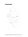
Fitting & Operating Instructions
for the Balmoral Electric Stairway
Remote Switching Model
The Balmoral has been manufactured and tested to ensure it operates
correctly for the chosen floor to ceiling height specified. Prior to its
installation, please check that the Structural opening in the ceiling is correct
and corners square. Ensure that there is a power supply available at the top
of the stair.
Important
When considering the location of the opening, it is important that the hinged
end of the lining is at least 130mm away from any obstruction at lower level,
i.e. a wall or door, so that the operating rod for manual use can be used
comfortably.
Electrical Preparation
(N.B. ALL ELECTRICAL WORK SHOULD BE DONE BY A COMPETENT PERSON)
A 1.5mm twin plus earth supply cable should be fitted to terminate adjacent
to the right hand front end of the casing, unless previously specified
otherwise. (Motor size = 230 volt 240 watt 1.1amp). This may be fitted with a
13 amp socket as the stairway is supplied fitted with a 3 pin fused plug. If
preferred the stairway may be hard wired to a switched 5 amp fused spur
after installation.
The unit is supplied with two remote control switches – one for upstairs and
one for downstairs. These switches will operate the stairway as soon as it is
plugged in. The top button will operate the stairway upwards, the bottom
button will operate the stairway downwards, and the middle button is to stop
the stairway anywhere in between. The limit switches on the motor will
automatically stop the stairway in its fully up/down position.
Units C & D, Ford Lane Industrial Estate Tel 0845 676 0704
Ford, Arundel, West Sussex, BN18 0DF Fax 0845 676 0705
[email protected]
www.loftcentre.co.uk
Installation Instructions
1. Place the unit on a dust sheet or packing on the floor to protect the
under surface of the lid.
2. Plug into extension lead and press the down button to slacken the
lifting tapes by approximately half a metre. The casing must then be
hinged up whilst the lid remains on the floor. The case should be
propped.
3. Use a 10mm spanner and remove the top nut off the M6 tension
adjustment screw where the tape is attached to the spring on the
bottom of the ladder. Carefully slide the loose section of the ladder out
and put to one side.
4. Undo carefully the M8 pivot bolts which attach the bottom of the
ladder to the wooden rails on the lid, retaining washers. Carefully
remove the fixed ladder section and put to one side.
5. Pull the two tape ends over the centre of the lid and fix their ends
together using an M6 bolt and nut (or similar). Remove prop and close
lid carefully, tightening the tape using the up switch.
6. The casing should now be ready with the lid tight shut for lifting into
the opening. On no account should the metal drop rods be used for
lifting, as they will bend.
7. Pre-drill the lining to take the coach screws or other substantial fixings.
Ensure that these will pick up appropriate positions on the opening
structure.
8. Offer lining and hatch unit into the structural opening and fix through
pre-drilled holes. We suggest fixing blocks onto the outside of the
lining and lowering it into the opening, using wedges to level the unit,
and then fixing it in place. It is best practice to lift the lining and door
unit up together, however for weight reasons it may be preferred to
remove the door. To remove the door - Unscrew the hinge that is
attached to the lining, since this is bolt-fixed and will make re-hanging
easier. Please reattach the door once the lining is in position, but
before it is fixed, so that you can check it is square. Please ensure that
the tape bolt is done up tightly.
9. Tighten up the fixings using packing behind to avoid distortion of the
lining and mis-fitting of the hatch. Ensure that the lining is level.
10. Connect the power supply and press the down button on the remote
control switch to release the hatch. If power is not available, the hatch
can be lowered using the manual winding arm. (N.B. The hatch
without the stairway attached may need some weight applied to help it
down.)
11. Offer up the stairway, and reattach.
Units C & D, Ford Lane Industrial Estate Tel 0845 676 0704
Ford, Arundel, West Sussex, BN18 0DF Fax 0845 676 0705
[email protected]
www.loftcentre.co.uk
Adjustment of the Stairway (See Fig. 4.)
Although the stairway has been set to the specified floor to floor
measurements, due to sloping floors, or other factors, a small adjustment
may be necessary. The foot of the stairway should sit nicely on the floor with
the top of the drop rod sitting firmly on the black stop. If the foot of the
stairway, or the drop rod is up in the air when the stair is fully down, please
adjust as follows:
1. Undo the locknut on the drop rod.
2. Loosen or tighten the drop rod as required.
3. Press the “lower limit” switch in order to loosen or tighten the tape
length.
4. Ensure that you reset the “lower limit” switch.
5. When adjustment is complete, tighten the locknut.
Setting the Motor Switches
This may be required if the floor to ceiling height is slightly different to that
specified at the time of the order. Also, adjustment may be necessary, since
the tape may stretch a little after initial use.
Important: Limit Switches
The limit switches need to be set to suit the current floor to ceiling height, to
protect the motor. If the limit switches’ settings need to be changed for any
reason, they must be reset immediately to protect the motor. Failure to do
this will result in damage to the motor and lifting mechanism.
Upper Limit:
1. Press the “upper limit” switch – it should lock down.
2. Press the wall switch until the stairway stores correctly (The lid should
shut and the tapes should be under tension.)
3. Press the stop button – N.B. Be careful not to pull the tapes too tight.
4. Press the “upper limit” switch again so that it pops up.
5. The upper limit is now set, check with the wall switch that the stairway
stops as required.
Lower
1.
2.
3.
4.
5.
Limit:
Press the “lower limit” switch – it should lock down.
Press the wall switch until the stairway descends to the floor.
Press the stop button.
Press the “lower limit” switch so that it pops up.
The lower limit is now set. Check with the wall switch that the stairway
stops as required.
Units C & D, Ford Lane Industrial Estate Tel 0845 676 0704
Ford, Arundel, West Sussex, BN18 0DF Fax 0845 676 0705
[email protected]
www.loftcentre.co.uk
Motor – Automatic Thermal Cut Out
The motor is designed to be as compact and unobtrusive as possible.
Consequently it has no cooling fans or through air draught as found on
normal, constant use motors. An automatic thermal cut out has therefore
been incorporated into the motor. This means that it may cut out after 2 or 4
operations whilst heat dissipates through the motor body. Under normal
circumstances the stairway would be lowered for use, and then returned a
while later. It is not designed for constant repeated operation, and this will
inevitably trip the thermal cut out. If the cut out is tripped, please leave for
15 – 30 minutes to allow it to return to ambient temperature.
Manual Operation
The Balmoral Electric Stairway offers the opportunity of operation manually in
the event of a power failure.
1. Insert the operating rod through the hole in the door and into the
hexagonal hole in the motor assembly.
2. Turn the operating pole until the door is lowered and the stairway is
securely on the ground.
3. To raise the stairway, turn the operating rod in the opposite direction.
4. To operate from above, insert the operating rod into the hexagonal
hole and turn rod as above.
Important
THE STAIRWAY IS DESIGNED FOR USE BY ONE PERSON AT A TIME ONLY.
THE STAIRWAY MUST NOT BE RIDDEN WHILST BEING RAISED OR
LOWERED.
Maintenance
No specialist maintenance is required for this unit.
It is recommended that all moving parts be lubricated with the PTFE spray
supplied, at least every six months or more frequently if required.
To Clean
The Ladder sections may be wiped with a damp cloth or with the use of
furniture polish and a duster.
Units C & D, Ford Lane Industrial Estate Tel 0845 676 0704
Ford, Arundel, West Sussex, BN18 0DF Fax 0845 676 0705
[email protected]
www.loftcentre.co.uk
Electrical Limit Switch Diagram
Units C & D, Ford Lane Industrial Estate Tel 0845 676 0704
Ford, Arundel, West Sussex, BN18 0DF Fax 0845 676 0705
[email protected]
www.loftcentre.co.uk