1
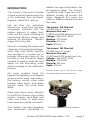
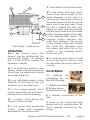
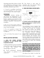
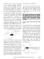
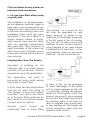
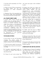
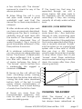
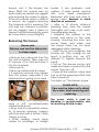
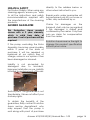
Installation & Operating
Instructions
Note: to prevent damage, do not attempt to operate this unit
before reading the manual thoroughly
‘THE ANSWER’
410, 325 INT (UK)
Manufactured by Evolution Aqua Ltd.
Evolution House
Kellett Close
Wigan WN5 0LP
Tel: +44 (0) 1942 216554
Fax: +44 (0) 1942 216562
Web: www.evolutionaqua.com
E-mail: [email protected]
INTRODUCTION
‘The Answer’ is the result of 4 years
of hard work and development by
a Koi enthusiast from Southport,
England, called Nick Jackson.
Like all other Koi enthusiasts
around the world Nick became
increasingly frustrated with the
endless amounts of algae, dust,
solids and fish waste escaping his
mechanical filtration stages and
entering his biological filtration
stages of his Koi pond.
This led to stopping the system and
cleaning out the biological stages,
which was both labour intensive
and resulted in a severe loss of
biomass. After every clean out, the
bacteria in the biological stages
needed to regroup and take hold
again via the fluctuating water
quality readings of the nitrification
process.
This same problem faces Koi
keepers and garden pond keepers
all around the world, especially in
the summer months when extra
feeding takes place and algae
blooms make the pond even
dirtier.
address this age-old problem. Like
all ingenious ideas ‘The Answer’
is simplicity itself. There are now 2
different models, all function the
same, designed the same but
cater for different sized ponds and
flow rates.
‘The Answer’ 410 Filter Unit
150/200 micron* screen.
Maximum flow rate 13,000 litres/2,863 gallons per hour
Voltage - 240 Volts / 50 Hz
Wattage - 270 Watts
Diameter: 410 mm
Depth: 400 mm
‘The Answer’ 325 Filter Unit
150/200 micron* screen.
Maximum flow rate10,000 litres/2,202 gallons per hour
Voltage - 240 Volts / 50 Hz
Wattage - 200 Watts
Diameter: 325 mm
Depth: 370 mm
*Actual
screen size is 150 micron unless
otherwise stated on the Answer box.
There have been many attempts
to rectify this situation such as filter
brushes, screens, sand filters and
other such ideas. To date none
have been even mildly successful.
‘The Answer’ has been designed
and developed specifically to
‘The Answer’ without its screen
Answer 410/325 INT(UK) Manual Rev. 1.05
page 2
A
C
‘F’ is the return line from the pump.
‘G’ is the hollow rotor arm which
is almost the same length as the
G inside diameter of the unit. It is
connected to the pump outlet and
the water leaves via the two jets at
each end of the rotor arm. Once
F
the unit is started the rotor arm
D
begins to rotate and the powerful
exit jets force water from the inside
B
H of the chamber against the inside
of the stainless steel screen. This
E
constant action prevents any
solids from sticking to the screen
on the outside of the unit. Instead
‘The Answer’ Components
the solids are dislodged from
the screen and settle out at the
OPERATION
bottom of the chamber, which
There are several ways ‘The houses the unit.
Answer’ can be installed into the
mechanical stages of filtration ‘H’ is a locking screw, which is used
but it is first best to explain the as a security lock so that you can
operation in detail.
not dismantle the pump when it is
running.
‘A’ is a reinforced stainless steel
screen, which only allows particles ON OPENING
of less than the screen size to enter
the inside of the unit.
On
opening
the
packaging you will
‘B’ is an adjustable sleeve, which find the following: attaches to the base of the unit
and then on to exit pipe work.
1. Stainless steel filter
2. Rubber sleeve
‘C’ is the locking fastener. This is 3. Backwash pump
used to bleed the unit and also to
remove the screen for cleaning.
2 is already connected to the
filter.
‘D’ is a spigot, which allows ‘the
Answer’ to be mounted.
3 needs to be connected and
locked with the locking screw ‘H’
‘E’ is the pump itself (backwash that is already screwed into the
pump), made and designed pump.
especially for the Answer units.
Answer 410/325 INT(UK) Manual Rev. 1.05
page 3
CONNECTING THE PUMP
Take the pump out of the box.
Remove the pump from the plastic
bag and remove the locking screw
H from the pump.
Carefully remove the elastic
bands from the pump housing
whilst holding the coloured rotor
in place, to ensure that the rotor
does not fall out from the unit. You
are now ready to fit the pump.
Turn ‘the Answer’ unit upside
down (fig. 1).
Holding the coloured rotor in
place and turn the pump upside
down (fig. 2).
Fig 1
Fig 2
Place the pump into position (fig.
3 & 4).
Fig 3
Fig 4
Turn the pump clockwise and lock
it into place (fig. 5).
Fig 5
Fig 6
Turn the unit, the right way up,
place in the locking screw ‘H’ from
the top and then secure it in place,
with 2-3 turns, by using a pozidrive
screwdriver. You are now ready to
install your filter.
The process is quick and
simple.
The sleeve is connected to the
relevant exit pipe work in the
prime
mechanical
container
and tightened fully to give a
watertight seal using a screwdriver
(not provided). Check also the
connection of the sleeve to ‘The
Answer’. Please ensure that the
pipe work is inserted fully into the
sleeve until it makes contact with
the spigot on the base of the filter
and then lift it up with 1” or 25 mm.
Installation and operating instructions of the pump connection.
Read instructions carefully before
attempting installation.
Attention: Thermal protection. In
order to help ensure your pump’s
long life and prevent possibility
of damage, it is fitted with an
automatic
thermal
overload
protection. This switches off the
pump if it overheats. If this occurs,
Answer 410/325 INT(UK) Manual Rev. 1.05
page 4
switch off the power at the mains
supply to the pump. Check
for the cause. Usually it will be
debris blocking the inlets of the
pump or obstructing the impellor.
Remove the obstruction and
allow approximately 15 minutes
for the pump to cool down and
automatically reset. Then switch
on the pump again. Note: you
must switch off the mains supply
before the pump will reset.
The pump does not use oil or
grease for lubrication and can be
used safely in ponds containing
fish or plants. The motor consists of
a sealed stator and water-cooled
rotor. All electrical components
are isolated from the water.
WARNING: SAFETY AND ELECTRICAL
CONNECTIONS.
1. The pump is supplied with 10m
of 3 core electric cable which
is permanently connected and
sealed to the motor. The supply
cable cannot be replaced. If the
cable is damaged, the pump
should be discarded. The plug
supplied with this product is not
waterproof and must be housed
in a dry weather-proof enclosure
fitted with a 3 or 5 Amp fuse. The
installation must conform to the
regulations of the local electricity
authority which could include the
use of plastic or metal conduit
to protect the cable. The pump
is designed to be permanently
wired to the mains supply in a dry
weatherproof enclosure through a
Double-Pole Switched Fused Spur
with a minimum contact gap of
3mm (dissconnector) to BS 3676
fitted with a 3 or 5 amp fuse.
2. A 10mA or 30mA Residual
Current device (RCD) must be
fitted to the mains supply.
3.WARNING: This appliance must
be earthed and it essential that
the connections are made using
the following code
Brown - Live
Blue - Neutral
Green/yellow - Earth
The brown lead should be
connected to the live terminal
which may be marked with an
‘L’ or coloured brown or red. The
blue lead should be connected
to the neutral terminal which may
be marked with an ‘N’ or coloured
blue or black. The Green/Yellow
lead should be connected to
the earth terminal which may be
marked with an ‘E’ or coloured
green or green/yellow.
4. If an extension cable is required
this should be connected to the
end of the pump cable using a
weather-proof cable connector.
The joint must be positioned in a
suitable dry housing. The extension
cable should be of 3 core 0.75mm2
polychloroprene rubber insulated
cable (ref: HO5 RN-F) and
permanently wired to the mains
supply with a 3 or 5 Amp fuse.
5. The pump cable (and extension
cable) should be positioned and
adequately protected against
Answer 410/325 INT(UK) Manual Rev. 1.05
page 5
damage especially where contact
with gardening equipment (lawn
mowers, forks etc.), children and
domestic animals may occur.
6. Consult a qualified electrician
or local authority if in any doubt
about wiring to the mains supply.
IMPORTANT
1.WARNING: always unplug or
disconnect all appliances in the
pond from the electricity supply
before putting your hands in the
water whilst equipment is being
installed, repaired, maintained or
handled.
2. Do not use the supply cable to
lift the pump or answer unit, as this
may cause damage
3. Do not operate or leave the
pump or answer unit in freezing
conditions.
4. Do not allow the pump to run
dry.
INSTALLATION SECTION
1. FOR KOI POND SYSTEMS
CURRENTLY IN THE DESIGN AND
PLANNING STAGES.
In these instances we recommend
using a Nexus specifically designed
to house ‘The Answer’. The
advantages of this are:A. Good settlement allowing
‘The Answer’ to perform to its
maximum.
B. The Nexus is very easy to
maintain with ‘the Answer’ fitted
into the central chamber.
2. FOR EXISTING FILTER UNITS.
a. Typical vortex-style filtration with
prime unit having a ‘central’ exit to
the next stages.
The installation here is simple; the
central exit pipe can be fitted with
a slide valve inside (or outside)
the vortex as shown. This allows
for quick and easy discharge of
the chamber without wasting
good water contained in the next
stages. Also, it prevents dirty water
from entering ‘The Answer’ from
the bio stage when emptying and
cleaning the prime tank/vortex. It is
also vital to have a slide valve prior
to the bottom drain line entering
the vortex.
Important. It has been discovered
during trials of prototypes that the
tube entering the prime vortex unit
MUST be extended upwards by
fitting a 90-degree elbow and a
short piece of pipe (as shown on
previous page).
This allows the water to enter the
Answer 410/325 INT(UK) Manual Rev. 1.05
page 6
container level with the centre
of the screen (upright position)
thus creating extremely efficient
settling out of all debris. As such
the spinning inside the vortex is
stopped rendering it a catchment
tank. If the spinning were allowed
to continue, fine debris would not
be allowed to settle and would
remain in suspension potentially
causing an overload to the screen
and subsequent decrease in
performance over an extended
period of time. This modification
should also be done in any prime
container, whether it is a round,
square or rectangular tank. In this
installation the vertical exit pipe
from the vortex may have to be
reduced in height to ensure the
unit sits completely below water
level in normal running. We suggest
the unit is located as near to midheight in the vortex as possible. This
although not being critical gives
better performance of the unit.
N.B. What is important is to have
the inlet pipe vertical and level with
half way up the screen of the unit
as shown above. If ‘The Answer’ is
fitted upside down, the inlet pipe
must be brought up vertically, but
NOT too close to water surface
level as this reduces pressure in the
pipe for line purges (150mm below
the water level is sufficient).
Once the unit is installed, open the
slide valve from the bottom drain
line and allow the vortex to fill to
normal level. The Answer pump
is now switched on to let the air
purge out.
N.B. check that the arm is rotating
by feeling the screen for pulses
of water from the screen before
leaving the backwash pump
running.
b. For vortex units with ‘side wall
exits’.
This is a little more complex as the
outlet tube has to be extended
and brought downwards centrally
into the vortex itself as illustrated.
Again a slide valve can be fitted
inside the vortex chamber. In this
installation the unit is installed
‘upside down’. If run in this position,
the unit still needs bleeding as
described before. Care must be
taken when fitting extra pipe work
that air locks are not created.
Bleed screws can be fitted to
bends in pipes if they create sites
for trapped air.
Answer 410/325 INT(UK) Manual Rev. 1.05
page 7
Call your dealer for any queries on
inlet pipe work conversions.
c. For box-type filters either pump
or gravity-fed.
This installation is self-explanatory
as the diagram illustrates, again a
slide valve is recommended here.
Fitting the unit to the induction side
of the main circulating pump is less
preferable than what we have
described. If the unit is fitted to a
system directly before a pump,
extra special care must be taken
with the cleaning maintenance
discussed later. This is because, a
slight blockage of the screen will
allow the pump to literally suck in
the screen causing the rotor arm to
stop spinning.
‘The Answer’ on a pond for the
first time. Be prepared for very
large amounts of debris to be
collected for discharge, especially
in the first week or two of running.
The unit will not allow most pond
particles to pass. Mature systems,
which appear to be clear before
installing this unit are in fact, ‘not so
mechanically clear as previously
believed’ - as the unit will prove!
Pumping direct from ‘the Answer’:
Important: If installing on the
induction side of a pump please
contact us for an air vent, which is
essential to use in this application.
This application will assist in
removing all heavy solids before
they enter a ‘bead’ filter.
In truth, there are few applications
that will not allow the fitting of
‘The Answer’ to any pond system.
However, if you are in any doubt
as to the best fitting methods for
best results in your system please
contact us for our advice.
Another
point
should
be
mentioned here to those fitting
In view of this, do be prepared
to make discharges of the prime
unit to waste regularly as the unit
is continually clearing all previous
debris out of the system. Once ‘The
Answer’ has done it’s job in clearing
the pond of the solids build-up from
the existing water, it will then be
able to operate with normal dayto-day feeding etc. Discharges will
not be needed so often once the
system is under control.
Answer 410/325 INT(UK) Manual Rev. 1.05
page 8
A minimum of 250mm is needed
below ‘The Answer’ to allow good
settlement, otherwise debris will
be held in suspension due to the
action of the rotor arm if the unit
is too close to the bottom of the
prime settlement tank.
MAINTENANCE SECTION
Maintenance of ‘The Answer’
Cleaning of the container, which
houses the unit depends on the
volume of the container in question
together with the amount of waste
collected, this varies dramatically
from pond to pond. How often you
choose to discharge the container
itself should be determined by
your own experience of your own
system.
Occasionally, in cases of high
stocking density, some customers
have noticed a loss of performance
of the filter, indicated by a slight
head loss in the end bio chamber
or a build up of waste matter
around the screen. This is caused
by a build up of bio film and can
be remedied easily. (See cleaning
section). The stainless steel mesh
can be scrubbed gently from
time to time with a cleaning brush
(nylon not metallic) or rubbed with
a damp cloth. A garden hose with
a high pressure nozzle is also a very
effective method of completely
cleaning the screen.
Please Note: Pay special attention
to the cleaning section at the end
of this booklet.
Important. Never run the unit
with the main pond circulating
pump turned off, this could draw
contaminated water from the
first bio chamber thus soiling the
inside of the unit. On installation
and every occasion that water is
lowered below the screen of the
unit, manually check by feeling for
a pulse that it is operating correctly
- never presume so.
‘The Answer’ should only be fitted
in the 2 horizontal planes as shown
earlier. It is recommended NOT to
fit it on its side where avoidable
because settlement is not as easily
achieved and the debris stays
in contact with the screen for
prolonged periods of time.
Maintenance of the Pump
The pump has been designed to
allow fast and easy maintenance.
As with all pumps of this type,
occasionally it will become
necessary to clean the rotor.
Always unplug or disconnect ALL
appliances in the pond from the
electricity supply before putting
your hands in the water or starting
maintenance.
1. Remove the locking screw from
the pump body.
2. Firmly rotate the pump out of its
location and remove.
Answer 410/325 INT(UK) Manual Rev. 1.05
page 9
3. Pull the rotor assembly out of the
motor body.
unit and new pipe work installed
to fit it.
4. Wash out all of the components
in clean water. Do not use
detergents or other chemical
cleaners.
4. Make sure that you have not
overloaded the prime with too
much waste matter. This has
happened to over enthusiastic
keepers doing demos at home
and putting in a full bucket of solid
waste to see what it will handle.
Be realistic, the unit will handle the
dirtiest pond but there is a limit.
The flow rates quoted for each
‘Answer’ model are a maximum
flow rate per hour in average
pond conditions and may need to
be reduced in dirty conditions until
the filter has had time to remove
the majority of the solids from the
water, this improvement period
may take several weeks.
5. Replace the rotor assembly into
the motor body and reassemble
the pump and the locking screw.
ALL YEAR PUMP CARE
A quick daily check should be
carried out to ensure that the
pump is performing satisfactorily.
Once a month, remove and
clean the pump in accordances
with the general maintenance
notes. Depending on pond water
conditions, cleaning may be
required more frequently. Once a
year, completely disassemble the
pump including the rotor assembly
as described in the general
maintenance above.
TROUBLESHOOTING
In the event of the unit blocking
causing the prime vortex to
overflow or the bio-chambers to
empty, please check the following:
1. Check power supply to pump by
feeling pump body (it will vibrate if
running).
2. Consider prolonged build up
of waste on screen and treat as
described later.
3. Check for air locks inside the
5. Make sure the boot is fitted
properly and not leaking in dirty
water causing the unit to
block from the inside.
6. Remove the lid of the unit and
manually check the rotor arm is
spinning freely inside and not stuck
by an obstruction.
7. If none of the above resolves the
problem ring Evolution Aqua for
further support.
CHECKLIST ON INSTALLATION
1. Make sure you have not created
any obstructions or air locks in the
pipe work you have altered to
accept ‘The Answer’. We suggest
running your altered system for
Answer 410/325 INT(UK) Manual Rev. 1.05
page 10
a few minutes with ‘The Answer’
removed to check for any of the
above problems.
2. When fitting the unit to your
exit pipe work, ensure a good
watertight seal and that the
sleeve has not become pleated or
crimped.
3. Alter whatever entry pipe work
you have as previously described,
making sure the flow is coming in
vertically and at least level with
the centre of ‘The Answer’ screen
creating a downward flow of
water towards it. This is crucial for
good immediate settlement of the
finer particles it removes.
Head Loss / Flow Restriction
4. In whatever catchment tanks
you use, ensure an adequate area
below ‘The Answer’ of dead water
to allow settlement. N.B. a small
box filter with 100mm or 125mm
of space between the base of
‘The Answer’ and its bottom floor
is inadequate. We suggest a
minimum of 250mm.
5. Never run the unit without the
main circulating pump running.
Never drop the prime tank without
closing the slide valve described
before. Both of the last 2 could
cause interior contamination of
‘The Answer’ due to back flushing
of waste from the first bio tank.
6. Never run more than the
recommended maximum flow
rate for each unit through your
main circulating pump.
7. The head loss that may be
expected through our unit is
shown below. Exit pipe work in
bio chambers can be shortened
accordingly if they are running
currently at virtually water surface
level.
HEAD LOSS / FLOW RESTRICTION
Every filter system experiences
some head loss / flow restriction
through its inter connecting pipe
work. The chart below will show
the extra head loss / flow restriction
that can be expected after fitting a
new or recently cleaned ‘Answer’
into the system i.e. on a gravity fed
system with a flow rate of 10,000
litres per hour a 325 ‘Answer’
would cause the end bio chamber
to drop 50mm lower than its pre
‘Answer’ level. These restrictions
may increase indicating a need to
clean the screen after time. (See
cleaning section).
60mm
325 Unit
50mm
410 Unit
40mm
30mm
20mm
10mm
0
0
1000
2000
3000
4000
5000
6000
7000
8000
9000 10000 11000 12000 13000
Litres Per Hour
CLEANING ‘THE ANSWER’
Whilst ‘The Answer’ is a selfcleaning mechanical filter, it
has always been advertised as
Answer 410/325 INT(UK) Manual Rev. 1.05
page 11
‘truly low maintenance.’ That
title means that it will need some,
albeit infrequent cleaning so that
it carries on working at ‘day 1’
performance levels. The cleaning
consists of a 15-minute treatment
of the screen and will need to
be carried out once a decline in
performance of the system has
been experienced. There is always
a slight head loss when running
‘The Answer’ in a system. This will
vary according to flow rates and
is covered in more detail, re: the
graph on the previous page. If this
head loss starts to increase and
affects the running of the system,
generally it is an indication that
this quick cleaning process needs
to be performed. The cause is a
build up of bio film, which grows
on every surface in a pond system
and has the effect of gradually
closing the holes in ‘The Answer’
screen. The frequency of cleaning
will start to decrease as the pond
becomes cleaner and the TSS and
BOD start to drop within the pond,
reducing the growth of biofilm
on the screen. Generally, the first
cleaning will be required after 2
to 3 months in normal conditions.
Subsequent
treatments
will
become less frequent.
Methods of cleaning
Weekly general maintenance that
most ‘koi keepers’ tend to do, could
include hosing the screen or giving
it a wipe or a light brush to remove
any dirt that has accumulated.
Once this build up becomes
more intense and the time delay
between these types of cleaning
decreases, a 15-minute special
treatment is needed. This can be
done using a cleaning fluid that we
have tested and recommend due
to its efficiency and results. It can
be bought in a slightly different
form at most good hardware
stores worldwide (for example B
and Q). It is sold as ‘caustic soda’
(soda lye), which is a granular form
of sodium hydroxide. It is normally
sold at 30% concentration, which
is relevant to the preparation of it
prior to cleaning. Always follow the
instructions on the packaging. The
required cleaning solution should
be 15% strength and so a 1:1 mix
with water would be necessary
in the examples above. Make
sure that ‘soda crystals’ (sodium
carbonate) are not bought by
mistake as this substance is totally
ineffective. Once the correct
strength fluid is mixed the cleaning
is carried out as follows. You will
require about 300 ml or a cup full.
Note: -Sodium hydroxide is safe in
low levels for koi ponds. It is also
used in the aquaculture industry
as a pH buffer, but we suggest the
less contamination allowed to be
mixed with pond water, the better.
Cleaning ‘The Answer’
Turn off the relevant pumps, UV’s
etc. including ‘The Answer’ pump.
Close all valves going to, and from
your primary tank, or isolate the
filter chamber
containing ‘The
Answer 410/325 INT(UK) Manual Rev. 1.05
page 12
Answer’ unit. If ‘The Answer’ has
been fitted the normal way up
and is easily accessible we suggest
only removing the screen to clean.
If the unit is upside down or difficult
to access, we suggest removing
the complete unit for cleaning. The
unit may be cleaned in position
but we suggest care is taken to
prevent the fluid entering the pond
as it may affect your pH slightly.
Removing the Screen
Please note:
Extreme care must be taken due
to sharp edges.
• Remove the locking nut from the
top, anti clockwise. Take care not
to unscrew it too fast and drop it
into the chamber.
• Remove lid.
• Remove rubber seals & screen.
• If need be remove the rubbers
from the screen, especially if the
cleaning fluid is going to be used.
bodies. If any problems, note
position of spray heads, remove
with cross head screwdriver.
Backwash with hose and rinse to
ensure clean. Replace in same
direction as removed.
• After a 15 minute minimum
standing time, rinse the screen
thoroughly with hose or jet wash,
(avoiding grass areas).
• Replace the rubbers to the
screen and return to the main
housing, checking the rotor arm
moves freely and make sure
the screen mesh has not been
damaged whilst cleaning.
• Refit the lid and re-tighten the
locking nut. (The locking nut will
reach a positive stop, do NOT
attempt to tighten beyond this
point).
• Turn on ‘The Answer’ pump, and
make sure there is a pulse from the
screen. Then turn off.
• Open all the isolation valves and
turn on all the equipment that had
been turned off.
Turn back on ‘The Answer’ pump.
PLEASE NOTE:
Care must be taken not to distort
the screen, when removing and
replacing.
• Brush screen with cleaning fluid
using a soft uncontaminated
natural bristle brush.
• Allow liquid to penetrate screen
for 10 minutes minimum, reapply
with fluid and wait a further 5 mins
(15mins in total).
• Whilst waiting, check spray
nozzles for blockage, or foreign
Top screw, which is used for
bleeding in up-right position, also
for removing lid and screen.
Answer 410/325 INT(UK) Manual Rev. 1.05
page 13
HEALTH & SAFETY
For Product Safety: When using any
cleaning agents, ensure you refer
to all the instructions and safety
recommendations supplied with
the manufacturer of the cleaning
products.
ANSWER GUARANTEE
This Evoluation Aqua product
comes with a 2 year warranty,
which is valid from date of
purchase. Proof of purchase will be
required.
If the pump, excluding the Rotor
Assembly, becomes unserviceable
within 2 years of the date of
purchase it will be repaired or
replaced at our option free of
charge, unless in our opinion it has
been damaged or misused.
directly to the address below or
other when instructed to you.
Repair works under guarantee will
be performed only by our house or
a firm, duly authorized by us.
Claims for damages on the
transport shall only be recognized
if the damages is stated and
confirmed by the carrier. Only then
can we claim for compensation
from the carrier.
Evolution Aqua reserve the right to
change this product specification
without prior notice.
Liability is not accepted for
damaged due to accident,
improper installation or use. Liability
is limited to replacement of the de-
fective parts. This guarantee is not
transferable. It does not affect your
statuary rights.
To obtain the benefits of the
guarantee, firstly contact Evolution
Aqua service department who
may request that the pump is
sent along with proof of purchase
Answer 410/325 INT(UK) Manual Rev. 1.05
page 14